Development of a Soft Robotics Diaphragm to
Simulate Respiratory Motion
J. (Jeroen) van Dorp
MSc Report
Committee:
dr.ir. H. Naghibi Beidokhti
dr.ir. M. Abayazid
dr.ir A.Q.L. Keemink
prof.dr.ir. G.J.M. Krijnen
July 2019
024RAM2019
Robotics and Mechatronics
EE-Math-CS
University of Twente
Summary
The respiratory-induced motion of the liver introduces challenges in the medical field. This motion makes it difficult to do needle insertions at the right position and to aim the radiation beam at for example a tumour in the liver. Nowadays MRI is increasingly used for guidance during the aforementioned procedures, because it gives improved contrast on soft tissues and can therefore aid the navigation of the needle or radiation beam.
In this project a device is made that can simulate this respiratory-induced motion of the liver. This is done with the purpose that other robotic systems can be tested on it and that clinicians can practice procedures on the device. The device is made such that it is MR compatible and can fit inside an MRI machine.
For the design of the device close attention is payed to the human diaphragm. This resulted in a soft robotics diaphragm incorporating two different types of actuators. With these actuators it is able to simulate motion comparable to those of the human diaphragm. These actuators have first been designed and characterized. After that they have been implemented in the di-aphragm, which has again been characterized. Next to the diaphragm a liver phantom and a stand to support the diaphragm have been designed.
Preface
I would like to thank my supervisors Hamid and Momen for, first of all, introducing me to ’the world of soft robotics’, with which I was not familiar. I would also like to thank them for the fruitful discussions about this project and their advice. The technicians Sander and Henny must also be thanked for their input on the design of the molds for the actuators and the other parts that have been custom made for this project. Without that advice the fabrication of the actuators would have taken a considerable longer time. Someone I should also thank is Jan Lenssen for designing and fabricating the Arduino shield that I and a lot of other students used to control the pressure regulators.
Jeroen van Dorp
Contents
1 Introduction 1
1.1 Background of the project . . . 1
1.2 Anatomy . . . 1
1.3 Research question and sub questions . . . 3
2 Approach and conceptual designs 4 2.1 Requirements . . . 4
2.2 Approach and assumptions . . . 4
2.3 Initial concept . . . 5
2.4 Soft robotics . . . 5
2.5 Elasticity of the lungs . . . 8
2.6 MR compatibility and safety . . . 8
2.7 Concepts . . . 9
2.8 Dimensions . . . 11
2.9 Controller, software and user interface . . . 11
2.10 Summary and next step . . . 12
3 Design, production and testing of actuators 13 3.1 Pneumatic artificial muscle . . . 13
3.2 Pneunet bending actuator . . . 16
3.3 Vacuum actuated muscle inspired structure . . . 20
3.4 Summary and next steps . . . 29
4 Design, production and characterization of the diaphragm 30 4.1 Stand . . . 31
4.2 Liver phantom . . . 31
4.3 Design, analysis and production of the diaphragm . . . 32
4.4 Testing . . . 37
4.5 Characterization for the models . . . 41
4.6 Summary and next steps . . . 51
5 Model of the diaphragm and control 52 5.1 Model . . . 52
5.2 Control . . . 55
5.3 Validation of control . . . 57
5.4 Summary . . . 60
6.1 Discussion of the specifications . . . 62
6.2 Recommendations for future work . . . 63
6.3 Answers to the research questions . . . 64
7 Appendix 66
7.1 Schematic drawings of actuators . . . 66
7.2 Code in the 20-sim controllers . . . 69
1 Introduction
1.1 Background of the project
The motion of the liver due to respiration during procedures introduces some challenges in the medical field. For example a tumour in the liver moves with respiration (Rohlfing et al., 2004). Inserting a needle at the right spot or aiming a radiation beam (Shirato et al., 2004) can therefore be rather difficult and requires the right timing for needle insertion and some practice in order to do it correctly.
In this thesis the research and development of a soft robotics diaphragm that can simulate the motion of the liver caused by respiration will be described. Such a system can be specif-ically interesting for testing other robotics systems such as robotic needle insertion devices and they can help in training clinicians for image guided percutaneous needle intervention for treatment and diagnostic purposes, such as ablation and biopsies. MR imaging is increasingly used for interventional procedures as it gives improved contrast compared to other imaging methods on soft tissues (more than for example ultrasound) and can therefore help with the ’navigation’ during these procedures. Next to that MR imaging is non-invasive.
Previous work
There was already a device available to simulate this motion at the Robotics and Mechatronics group at the University of Twente, but there is the need for a more realistic and improved ver-sion. The device that was already available moves a liver phantom on a plate in 2 dimensions, this was done with help of soft-actuators and was MRI compatible (Naghibi et al., 2018). Also other work has been done to create respiratory simulators for liver motion. However, the mo-tion was limited (Müller et al., 2007), it was not MR compatible (Abayazid et al., 2018) or momo-tion itself was correct, but not dynamic (Lee et al., 2010). A complete new design will be made where the liver phantom is moved by a soft robotics diaphragm, similar to what would happen in the human body, where a large part of the respiration is facilitated by the motion of the diaphragm (Marieb and Hoehn, 2007). The human body will therefore be the main source of inspiration for the design of the device. For this reason the anatomy of the human diaphragm will be briefly explained next.
1.2 Anatomy
1.2.1 Liver
The liver is the largest internal organ of the human body (Marieb and Hoehn, 2007) and hepatic cancer has been one of the leading causes of cancer deaths(Bray et al., 2018).
The liver can have different shapes and dimensions, but it is at least sex and age related and some data suggests it is also region, BMI and/or alcohol consumption related (Wolf, 1990; Chouker et al., 2004; Verma et al., 2010; Kratzer et al., 2003). Different data can be found, but the average volume of the liver should be 1086 cm3and 1006 cm3for respectively male and fe-male. Whereas an unhealthy liver can be much larger, cases of livers with a volume of almost 4000 cm3can be found for patients with Chronic Hepatitis for example (Nagasue et al., 1987). The diameter measured from left to right is somewhere between 10.6 cm and 25.3 cm, for back to front that is somewhere between 6.2 cm and 20 cm and the height is somewhere between 13.8 cm and 24.9 cm(Verma et al., 2010).
1.2.2 Diaphragm
Figure 1.1:Schematic drawing of the diaphragm (Troyer and Wilson, 2016) and the liver
Two muscle groups can be identified in the diaphragm, the costal muscles that are on the sides attached to the ribcage (the zone of apposition) and the crural muscles that are around the esophagus (Pickering and Jones, 2002). For respiration they work synchronously together, but for example during swallowing they do not. By contracting the costal muscles the diaphragm can move downward. Relaxing those muscles again will cause the diaphragm to move upward again. This is due to the elasticity of the lungs. A motion of the ribcage can also be identified which helps facilitating the motion of the diaphragm and respiration in general. For the de-sign of the soft robotics system only the diaphragm itself will be looked into, the motion of the ribcage will be neglected.
1.2.3 Motion of the liver
Figure 1.2:SI motion of a tumour in the liver, indicated by the red circle(Abayazid et al., 2018)
1.3 Research question and sub questions
The main research question is: How to develop an MR compatible liver phantom that is actu-ated by a bio-inspired diaphragm to simulate respiratory-induced motion? Several sub ques-tions that need to be answered are:
• How can the device be made MR compatible?
• How can the diaphragm be inspired by the human anatomy?
• What kind of actuators can be used to develop this diaphragm?
• How can a realistic respiratory motion be generated?
• How can the device be made such that it can be used for testing purposes of robotic systems and training purposes for clinicians/surgeons?
2 Approach and conceptual designs
The starting point of the design will be the human diaphragm. By identifying what kind of mechanisms the human diaphragm uses to achieve its motion inspiration for the design of the robotic diaphragm can be acquired. Eventually the goal for the robotic diaphragm is to mimic the respiration motion and perhaps similar mechanisms can be used for that.
2.1 Requirements
Based on the research that has been done the requirements for the robotic diaphragm can be determined. The physical aspects, safety and usability are important for the device. Taking this into account the following requirement can be derived:
• The robot needs to be MR safe and sufficiently MR compatible
– The part that goes inside the scanner bore should not cause artefacts that can ob-scure the region of interest
– The system needs to fit inside a scanner with a bore of 50 cm, which is assumed to be the smallest MRI scanners that is commonly used for this application
• The motion of the liver needs to be accurate
– Between 0 mm to 8 mm in left-right (ML) direction
– Between 4 mm to 14 mm in up-down (SI) direction
– Between 2 mm to 8 mm in front-back (AP) direction with preferably the possibility of creating a difference between left and right
– Frequency that should be achievable is 0.25 Hz to 0.3 Hz
– Optional: taking into account the motion of for example heartbeats
• The set-up will represent a patient in supine position
• The design of the set-up will be inspired by the human anatomy
• The user interface should be such that it is usable by clinicians
2.2 Approach and assumptions
With the requirements set the approach is to first explore the possibilities for actuators that can be used for the diaphragm, where the main focus will be soft robotics because of the MR com-patibility and compliance. Based on this concepts for the diaphragm will be thought of to give a direction for the design of the actuators. This will lead to the design of the actuators which will be used to realize the diaphragm. These actuators can be tested and characterized to get an insight in if and how they will function in the diaphragm. First focus will lie on developing the device for one directional motion. Thus allowing the liver phantom to be moved up and down (SI motion) in a manner that is similar to what happens in the human body. After that is accomplished the device will be developed further to be able to move the liver phantom in all directions. The approach for further development of the device such that it functions in more directions will be determined based on the results of the first design. Next focus will lie on im-proving the control of the motion and making a user interface that is easy to operate, also for clinicians.
the surrounding tissues. The diaphragm itself will already give a lot of design freedom as will become clear in the following chapters.
2.3 Initial concept
It has been identified that the human diaphragm is in a dome shape when it is in a relaxed state and that it is in a more flattened shape when contracted. So for the soft robotics diaphragm ac-tuators to reach these two states need to be present. Useful acac-tuators to look into are therefore actuators that can bend (to go into the relaxed dome shape) and actuators that can contract (to flatten the diaphragm). Since the device also needs to be MR compatible actuators without metal are preferred, this makes soft robotics, ideal as will be explained next.
2.4 Soft robotics
Soft robotics have been around for some time already, but definitely not all possibilities of them have been explored yet (Trivedi et al., 2008). What distinguishes soft robotics from ’nor-mal’ robotics is the fact that the actuators are soft. Most soft robotics actuators do not require any metal for example, which is often the case for most other actuators. The fact that it does not require any metal means that it is more easily possible to create MR compatible robots. That is what makes it particularly interesting in the case of designing a soft robotics diaphragm which needs to be used inside an MRI device. Another advantage of soft robotics is the compli-ance, which most soft robotics actuators have. This makes it ideal for interaction with humans (Agarwal et al., 2016; Yap et al., 2017), but it can also be beneficial for the development of the soft robotics diaphragm as the real human diaphragm has some compliance. Several types of soft robotics actuators that can be interesting for the design of the soft robotics diaphragm are looked into. They will be introduced and explained next.
2.4.1 Mckibben actuators or pneumatic artifical muscles
A soft robotics actuator that has been in use for multiple purposes for quite some time is the McKibben muscle, also known as the pneumatic artificial muscle (PAM). A schematic drawing of an artificial muscle can be seen in figure 2.1.
Figure 2.1:Schematic drawing of an artificial muscle (Daerden and Lefeber, 2002)
In the 1950’s and 1960’s it was developed in artificial limb research(Chou and Hannaford, 1996; Pritts and Rahn, 2004). These actuators are built up out of an expanding tube surrounded by braided cords. When the tube expands by applying pressure to it (via some kind of pump) it pushes against the braided cords/mesh, which cannot expand. This causes the whole ’muscle’ to contract. Several factors influence the working of the artificial muscles, such as the friction of the mesh on the bladder, the type of material of the bladder and the geometry of the mesh. In general it can be said that when non uniformity of the mesh and friction is neglected and thin walls are chosen real world actuators can be described by equation 2.1(Obiajulu et al., 2013).
F=PπD
2 0
4 (3cos
2θ
WhereD0is the initial diameter of the mesh andθbeing the angle of the mesh as can be seen in figure 2.1, which can be further defined as.
contraction=l0−l
l0 =
1− cos(θ) cos(θ0)
(2.2)
This means force is depended on the actual pressure in the actuator, but also the current state/elongation/angle of the mesh, which means that the actuator is somewhat compliant, making precise open loop control hard. Based on this important design parameters are:
• Diameter of the bladder
• Angle of the mesh in unactuated state
• Length in unactuated state
The fact that these actuators contract makes them ideal to simulate muscles. Examples of their use are robotic hands (Faudzi et al., 2018) and cardiac compression devices (Obiajulu et al., 2013).
2.4.2 Fluidic elastomer actuators
[image:12.595.204.368.553.750.2]Fluidic elastomer actuators can be made in different shapes and sizes, but the essence is usu-ally the same. It is a soft stretchable material with compartments in it that can filled with air (or some other fluid), and example can be seen in figure 2.2. By controlling how much every compartment is filled with air it is possible to extend and bend these actuators in different di-rections. It is usually only possible to bend and extend these actuators, contracting with a pos-itive pressure of the fluid inside can only be done by McKibben-like actuators(Suzumori et al., 1992; Marchese et al., 2015). Some examples of their use are replicating a manta (fish) (Suzu-mori et al., 2007), caterpillars (Trimmer et al., 2006) or assistive gloves for rehabilitation (Yap et al., 2017). The way in which they move and the forces and torques they can generate depend on the design of the actuator. In general can be said that with thicker walls smaller forces and torques can be generated with the same pressure inside the actuator. However due to the fact that larger pressure can be applied before extreme ballooning or rupturing the actuator when the walls are thicker, usually the maximum force and/or torque an actuator can apply becomes larger with a larger wall thickness, but this again largely depends on the design/geometry of the actuator. Also the Youngs modulus of the material that is used makes a difference. (Sun et al., 2013).
2.4.3 Vacuum actuated muscle inspired pneumatic structures
Vacuum actuated muscle inspired pneumatic structures (VAMPS or vacuum actuators) differ from the previously mentioned actuators in the way that they are actuated. Whereas the other two that are mentioned are actuated by positive pressure (compared to the surroundings) a VAMPS is actuated with a vacuum. They are mostly based on the principle of mechanical instability and contract with a vacuum applied to them because of buckling of their internal structure. Their internal structure is also key in the way they buckle. For example contraction in a linear manner can be created, but also buckling causing a rotation in the actuator can be created by different structures. Previous research has shown that the actuation stress is in the same order of magnitude as that of human muscles and that as long as the geometric feature ratios are kept the same the behaviour of the actuator will stay the same. This means scaling up or scaling down a design should be fairly easy, making it ideal to work with (Yang et al., 2016, 2015). An example of a contracting VAMPS can be seen in figure 2.3.
Figure 2.3:Example of a vacuum actuated muscle inspired pneumatic structure(Yang et al., 2016)
The maximum loading stress is a function of the geometric features and the Youngs modules of the material that is used where it linearly scales with the Young modules. In general it can be said that the force (T) the actuator can generate is linearly dependent on the pressure (P) and the cross sectional area (A) of the active chambers in the actuator in perpendicular plane of actuation (equation 2.3). The strain (s) of the actuator (equation 2.4) is a function of the differential pressure (∆P) and the loading stress (σ). This strain is roughly linearly dependent on the differential pressure up until some critical pressure that is determined by the geometric features and that is again linearly dependent on the Youngs modulus of the material used. At this critical pressure the actuator is almost completely buckled, hence increasing the pressure difference will barely result in any motion.
T=P A (2.3)
s(∆P,σ)=L(∆P,σ)−L(0,σ)
L(0, 0) (2.4)
• For the same geometric features, differential pressure and Youngs modulus the output force of the actuator scales with the cross-sectional area of the actuator.
• The critical pressure with the same geometric features can be altered by choosing a dif-ferent Youngs modulus.
• In general the behaviour of the actuator can be changed by changing the geometric fea-tures.
VAMPS have some advantages over the positive pressure actuators; they are safer, since there is a smaller/virtually no chance on rupturing/exploding actuators. They are robust, because small holes may close themselves due to the negative pressure and they can be compacter. The last one is especially true when compared to the McKibben muscles which expands in radial di-rection when contracting, vacuum actuators just contract without expanding in any didi-rection, at least in the ideal case. Some research is being done into these actuators, but positive pres-sure actuators are found more often than VAMPS (Li et al. (2017)), which makes it interesting, but also more difficult, to look at for the robotic diaphragm.
2.5 Elasticity of the lungs
At rest the human diaphragm has a dome shape, because it is pulled upward by the elasticity of the lungs. So, it might be interesting to look at elastic materials that are MR compatible that can help replicate this elasticity of the lungs. If for example the soft robotics diaphragm would only be realized by contracting actuators getting the diaphragm into that dome shape might be difficult. An elastic material that is preformed in a dome shape could be useful for this. A material that might be used for this application is nitinol. Nitinol is a shape memory alloy, which means that the material can be deformed and stay in the deformed shape, but upon heating it will return to its old shape. Heating without it disturbing the MR image will be hard, so this is not ideal to use in the robotic diaphragm, but actuators have been made based on this principle (Jani et al., 2014). Some of these alloys also demonstrate super elasticity, which means that they can easily deform when a force is applied to it, but it can go back to its old form when it is released (Szold, 2006). It is an alloy that is often used in medical instruments and for example stents that can be placed in blood vessels. Even though they can introduce some artifacts on the MR image, often nitinols are MR compatible (Fischer et al., 2004; Holton et al., 2002). This superelastic material can also be used the other way around, so to flatten the diaphragm again. If for example only bending actuators are used it is possible to use the superelastic material that was preformed into a straight/stretched state to let the diaphragm go back to that state.
2.6 MR compatibility and safety
MR safety and compatibility of the robotic diaphragm will be essential as it will be used in an MRI device by clinicians. Next to that it is desired that a needle insertion device can be tested inside an MRI machine side by side with the robotic diaphragm.
it should not take up more space than an average human. This should allow for the ’normal’ instruments and tools to fit inside the machine just like when there would be a patient inside.
2.7 Concepts
Previously some potentially useful actuators and materials were identified. As mentioned two states of the diaphragm can be identified. Both can be seen in figure 2.4; the bend/dome state at the top (exhalation) and the straight/contracted state at the bottom (inhalation).
Designs made of only fluidic elastomer actuators are potentially an option, since the dome shape can be created with that. Straightening the diaphragm with only fluidic elastomer ac-tuators is difficult however, as they can only actively elongate or bend. For straightening the diaphragm PAM’s or VAMPS are potentially usable. Assuming the diaphragm is already in a dome shape it can be straightened by letting those actuators contract. The downside of PAM’s and VAMPS is that it is not possible to actively bend them. Thus getting the diaphragm back in a dome shape will be more difficult with those actuators. Getting the diaphragm back in the dome shape is something that can potentially be done with help of superelastic materials. If that material is pre-shaped in a dome shape, they can while the diaphragm is at ’rest’ keep it in a dome shape, but when the diaphragm is straightened it can deform with it. Based on these ideas several concepts have been chosen to further pursue and potentially develop.
Exhalation
(Bend or dome state)
Inhalation
(contracted or straight state)
A B
= PAM (contract) = Superelastic material
= Fluidic elastomer actuators (bend) = VAMPS (contract)
C D E
* = ‘Active’ part in current state
* * * * * * * * * * * * * * * * * * * * * * * * * * *
Figure 2.4:Multiple for the soft robotics diaphragm with different configurations of actuators. The di-aphragm is represented the same way as it is in figure 1.1
2.7.1 Combination of PAM and superelastic material
2.7.2 Combination of fluidic elastomer actuators and superelastic material
This design will be in principle the opposite of the previously mentioned concept where PAM and superelastic material are combined. In this case the fluidic elastomer actuators (in figure 2.4 B) will make the diaphragm bend and the superelastic material will generate the elasticity with which the diaphragm will move downwards. The downside of this design is that the force with which the diaphragm contracts cannot be well controlled. The advantage of this design is that is probably easy to produce. It should be a sheet with on top of that bending actuators and in the sheet there should be superelastic material.
2.7.3 Only PAM
This design probably has the most flexibility in terms of controllability, it can be seen in fig-ure 2.4 as C. It will have only pneumatic artificial muscles, again those that are embedded in the diaphragm which can straighten the diaphragm, representing costal muscles. In order to get the diaphragm in the dome shape there is another set of PAM’s. These will simulate the elasticity of the lungs. The advantage of this design is that the going into dome shape is well controllable as well and it is possible to do that with some force. This last part is a real advan-tage since the phantom liver needs to be attached to the diaphragm in order for it to move with the diaphragm. This will require some force which can be generated by the PAM’s at the top. Assuming for both the straightening PAM’s and the PAM’s that will pull the diaphragm back into its dome shape it should be possible to control all PAM’s individually. Resulting in good con-trollability in all directions that even makes it possible to move the diaphragm asymmetrically.
2.7.4 Combination of PAM and fluidic elastomer actuators
Another option (D in figure 2.4) is combining the PAM’s with fluidic elastomer actuators. Where the PAM’s will, like in the other designs, be used to straighten the diaphragm and thus push the liver phantom. Embedded in the diaphragm will be fluidic elastomer actuators which will allow it to bend, thus letting it go into the dome shape. Pneunet bending actuators are po-tentially suitable for this(SoR, 2018). A downside might be that it will be hard to manufacture this diaphragm as it requires PAM’s and fluidic elastomer actuators to be combined and the other issue is that it requires more pumps. For a smooth operation it would be desired to be able to control the PAM’s and pneunet actuators simultaneously, but that requires at least two pumps and preferably even more to control different groups of the PAM’s and pneunet actua-tors separately simultaneously, which might be a necessity to be able to get controllability in three dimensions.
2.7.5 Combination of VAMPS and fluidic elastomer actuators
This option is comparable to where the PAMs and fluidic elastomer actuators are used, but the PAMs are replaced by VAMPS (see E in figure 2.4. An advantage of this is that it should be easier to combine the two types of actuators into one diaphragm. All actuators can be made from on piece of elastomer and do not require any other materials in them. The downside for this type of diaphragm is that also vacuum regulators and a vacuum pump are necessary, which are not necessary for all the other concepts.
2.7.6 Issues for all designs
is something that will be looked into when the design of the diaphragm is made. Another issue with soft robotics is the compliance of the actuators. Constraints and external loads largely in-fluence the behaviour of the actuators and eventually the diaphragm. This will make it difficult to test the actuators and predict what they will do when used in a diaphragm. It will also be dif-ficult to compare the final diaphragm design with a human diaphragm based on anything else than motion. Defining anything like a mechanical impedance of the human diaphragm itself is nearly impossible as that depends on the muscles in the diaphragm, the state these muscles are in, the thorax and its muscles, the lungs, etc. For the soft robotics diaphragm this will de-pend on the constraints of the diaphragm, manufacturing errors, perhaps some hysteresis, etc. A straight comparison based on force or impedance will therefore be hard.
2.8 Dimensions
As mentioned previously the dimensions of the device should not exceed that of a normal hu-man, since it should not take up more space in an MRI. A stand needs to be designed holding the diaphragm in place. This needs to be sturdy such that no unwanted motions come from the stand. This design will be made based on the experience of the production of the actuators and the results of the experiments with them.
2.9 Controller, software and user interface
[image:17.595.153.452.497.727.2]In order to control the actuators and eventually the diaphragm hardware and software is needed. In order to control the pressure and vacuum in the actuators pressure and vacuum regulators are needed. Also hardware to interface between the software and the regulators is needed. From previous projects at the Robotics and Mechatronics group Festo pressure regula-tors are available. These are VEAB-L26-D7-Q-V1-1R1 and VEAB-L-26-D2-Q4-V1-1R1 for posi-tive pressure and VEAB-L-26-D14-Q4-V1-1R1 for vacuum. Next to that MHE2-M2H-3/26-QS-4 solenoid valves from Festo are available. These can be used to split the output of the regulators over multiple tube and thus actuators. This however does only allow for sequential control of actuators that are connected to the same regulators via a solenoid valve. Also an Arduino shield is already available (figure 2.5) that allows for four regulators to be controlled and read-out si-multaneously and four solenoid valves to be controlled.
Schematically this set-up is depicted in figure 2.6. Since the control is essentially done by an Arduino there are multiple options to make the software. Especially useful if this set-up is going to be used in for example hospitals. Eventually a user interface will be made such that it can run without the need of Matlab or any programming skills for the user. Customizable breathing loops should be possible.
[image:18.595.83.494.157.394.2]Pump for pressure Pump for vacuum Pressure regulator Vacuum regulator Solenoid for combining Solenoid for splitting Solenoid for splitting Actuator only pressure Actuator only pressure Actuator only vacuum Actuator only vacuum Actuator vacuum and pressure Arduino Laptop Pneumatic tube Wiring/cables
Figure 2.6:Control set-up depicting several options of controlling several types of actuators via an Ar-duino with a laptop. Blue lines depicting air hoses and grey lines depicting signal wiring.
2.10 Summary and next step
3 Design, production and testing of actuators
In this chapter the design of the actuators, their FE models, molds, the production and testing will be discussed. The process from design to characterization will be explained for one ac-tuator completely, after which this is done for the next acac-tuator. The first assumption for the diaphragm is that it is around 200 mm by 300 mm when contracted, based on this several actu-ators are made as a proof of concept. These dimensions are chosen based on the liver phantom size and the maximum dimensions the final device should have. The start for every actuator is that it is modelled and an FE model is made from that, if that is feasible. Based on the outcome of the FE model dimensions can be adjusted. Next the actuator can be fabricated and char-acterized to get an insight in how they can be used in the diaphragm. For all actuators there is chosen to make them out of Ecoflex 00-50 and 00-30, because at the lab there was already experience with this material and this material is also often used in designs found in literature (Yang et al., 2016; SoR, 2018). Eventually mostly Ecoflex 00-50 is used, because this is easier to work with than Ecoflex 00-30 due to the higher viscosity.
300 mm width
200 mm height Thickness t.b.d.
Figure 3.1:The initial dimensions chosen for the diaphragm as well as the naming of the dimensions
3.1 Pneumatic artificial muscle
The purpose of this actuator is that it is able to contract. It can then be used to either let the diaphragm go into the dome shape (see figure 2.4 C) or to let the complete diaphragm contract and straighten (see figure 2.4 A, C and D). The important design parameters were previously identified as:
• Diameter of the bladder
• Angle of the mesh in unactuated state
3.1.1 Actuator design
The most important part of this actuator is the bladder. This is a bladder that can be made from an elastomer and is schematically represented in figure 3.2. In this case there is chosen for Ecoflex 00-50 and Ecoflex 00-30. The starting point of this design is previous research (Obiajulu et al., 2013) where a wall thickness of 2 mm is suggested. The length of the bladder is chosen such that two of these actuators could be combined with other actuators in the final diaphragm and is set to be 93.75 mm, with the assumption of around 20% contraction this should result in a muscle of 75 mm. This means the first important design parameter, the length in unactuated state, is set.
Another design parameter is the diameter of the actuator. This is based on the mesh that is already available in the lab, which is 15 mm. The diameter of the bladder is therefore taken to be 14 mm. This also sets the last design parameter, because the mesh that is already available has an angle of 30 degrees. The force the actuator can generate is at first not the most important design parameter, because of two reasons. The first one being that if one actuator is not strong enough it should be possible to incorporate multiple actuators in parallel. Next to that it is hard to determine what the minimum required force would be when the actuator is incorporated in the diaphragm.
Furthermore the ends of the bladder are chosen to be 5 mm thick such that these do not ex-pand much and one side has an opening for a pneumatic tube to be attached to. The actual attachment of the mesh can be done with a combination of wire and tape.
5 mm 5 mm
2 mm 93,75 mm
14 mm
Airchamber Bladder wall
Inletforpneumatic tube
Figure 3.2:The bladder of the artificial muscles schematically represented
3.1.2 Mold and fabrication
Based on previous knowledge and insights from the technicians at the Robotics and Mecha-tronics group a mold has been designed. Based on the dimensions previously mentioned a CAD model in Solidworks has been made that could be 3D-printed by an Objet 3D printer. The mold consists out of three parts. Two for the outside of the bladder, these are translucent such that it can be seen how far the Ecoflex has already filled the mold and one for the inside of the bladder which is attached to the top of the mold. The mold with at the bottom of the image the fabricated bladder can be seen in figure 3.3.
Outer mold Bladder
Inner mold
Figure 3.3:The mold of the Pneumatic artificial bladder with a finished bladder
Fabrication is done in several steps; Seal the mold with tape, prepare the Ecoflex as described on the packaging and pour it in the mold. It is essential that more than enough Ecoflex is prepared and that the degassing of the Ecoflex is done sufficiently. Next to that there is a small difference in how to make the actuator with Ecoflex 00-50 and Ecoflex 00-30. Ecoflex 00-50 cures faster than Ecoflex 00-30 and does not leak from the mold, whereas Ecoflex 00-30 does leak. Ecoflex 00-30 needs to cure for 20 min minutes before it is poured into the mold, this causes the viscosity of Ecoflex 00-30 to be higher and prevents leaking from the mold. After that the process is the same for both. The pneumatic hose can be attached with help of wire and duct-tape. The design of the mold does have an issue. The top does have some play and since the walls are thin it can happen that the wall thickness is not homogeneous. With the mesh around it this is not really an issue any more however. The implication for the design is however that if the basic design of the mold is kept the same it is almost impossible to have thinner walls, because chances are the walls will not fully close.
3.1.3 Characterization
The aim of this characterization is to find the relation between applied pressure to the artificial muscles and the contraction while unconstrained. This is done by applying pressure in steps of 0.1 bar up to the pressure where the muscles start leaking a lot of air. For every pressure step the length of the actuator is measured, see figure 3.4. Comparing the initial length of the actuator to the contracted length of the actuator results in the contraction.
Figure 3.4:The finished PAM, at the top contracted and at the bottom relaxed
specific actuator. All actuators show a contraction of 20-25% (absolute contraction of the ac-tuator compared to the bladder of 97.5 mm) before leaking does not allow for an increase in pressure any more. Contraction versus pressure can be seen in figure 3.5 for three different ac-tuators with the same design. Contraction is virtually instant after applying the pressure. It was possible to lift a 500 g weight of the ground by just contracting the muscle, with only a slight reduction of the contraction that could be achieved. What can be seen is that there is definitely a difference between several individual actuators. This is most probably due to the fact that it is difficult to attach the wire and tape in the same manner every time. This might be something to look into in the future, even though maximum contraction is comparable it is desired to also have contraction at the same pressure to be more similar for multiple artificial muscles. This would allow for better feed forward control as the behaviour is more predictable in that case. When looking at the difference between Ecoflex 00-50 and Ecoflex 00-30 there is only a slight difference at low pressures. Since Ecoflex 00-50 is easier to work with this is the best choice to make the material of the bladder from.
3.2 Pneunet bending actuator
The purpose of the pneunet bending actuator is to bend. As can be seen in figure 2.4 B,D and E. As fluidic elastomer actuator there are several design parameters as previously discussed. These are:
• The shape of the actuator and the air chambers in it
• Youngs modulus of the material of the actuator
• Wall thickness of the air chambers
3.2.1 Actuator design
Figure 3.5:Contraction versus pressure for three different, but in design identical, PAM’s.
has been shortened and widened such that it is more suitable to be used in a diaphragm in terms of outer dimensions of the actuator. The width now is 200 mm, which is the same as the height of the diaphragm to be designed. The width is 50 mm, such that 3 in combination with 2 artificial muscles would give a width of the diaphragm of approximately 330 mm.
The forces that need to be generated and how to measure them such that they are representa-tive for the final application in the diaphragm is hard to determine. Eventually a load (the liver phantom) will be distributed over a large part of the diaphragm and thus actuator. For this rea-son again outer dimensions and potential displacement/deformation (which needs to be in the range of the requirements of SI motion) as well as manufacturability are mainly taken into ac-count in this design. If necessary adjustments to the design will be made based on simulations and test results from where the actuator is loaded with different weights.
A schematic drawing of the design with the most important parameters can be seen in figure 7.1 in chapter 7. Four air chambers can be found in every actuator with the ’active’ walls having a thickness of 2 mm. These walls will bulge outwards when pressure is applied to the actuator. This means that walls will start touching and push the air chambers away from each other. Because the bottom of the actuator is one sheet of Ecoflex the actuator is not able to expand there. The result is that it will start to bend, because the top of the actuator is not constrained. With this the shape of the actuator and the wall thickness is set. As for the Youngs modulus of the material of the actuator, there is chosen for Ecoflex 00-50, which has a Youngs modulus of 2.17 MPa.
A CAD model has been made with Solidworks of the actuator before production. This in order to easily create a mold, but also to be able to simulate the behaviour of the actuator before production would start.
3.2.2 Mold and fabrication
The design of the mold is also derived from the soft robotics toolkit website (SoR, 2018). Addi-tions to that design have been made, such as an opening for a pneumatic hose and notches to put a screwdriver in the mold to make demolding easier. This mold consists of three parts, the first two to make the top of the actuator and the last one to makes the bottom of the actuator (see figure 3.6).
A
B
C Inlet for tube
Notch for screwdriver
Figure 3.6:Mold for the pneunet actuator. With A and C the bottom can be made and with part B and C the top of the actuator can be made
Fabrication of this actuator is straightforward. It is made from Ecoflex 00-50. First the top part containing the air chambers and interconnecting channels is made. Once that is cured the bot-tom can be attached to the top, which will seal of the actuator. For this type of actuator there are two difficulties while producing it. It can happen that some of the air channels between the chambers are closed of while placing the top on the bottom, which makes it impossible to actu-ate all chambers. This can be solved by cutting the actuator open and making the air channels free of Ecoflex after which the parts can be put together again with some new Ecoflex. Another issue is the fact that the opening for the pneumatic tube sometimes gets filled with Ecoflex. This can be fixed by puncturing it with a screwdriver after the Ecoflex has cured. Although this needs to be done carefully in order not to puncture any other parts of the actuator.
3.2.3 Characterization
Characterization of this actuator has been done in a an as free as possible state. Which has been done by measuring several points on the actuator and looking at their displacement while applying different pressures in steps of 0.01 bar to the actuator as can be seen in figure 3.7. This has been done by taking photos of the actuator in every state and processing that data with ImageJ software . The actuator has been put on top of a smooth surface that has oil applied to it in order to reduce friction. The goal is to find the relation between the displacement of the red dot (middle of the actuator) and the input pressure.
of the weight. A weight of 500 g and 1000 g including a plate of 110 g to support the weights on top of the actuator could be lifted, respectively 8 and 4 mm in vertical direction from its starting position. The lifting of the 1000 g weight can be seen in figure 3.8. Which led to the conclusion that the actuators incorporated into a diaphragm might also generate enough force/displace-ment to be able to move a phantom liver, at least the force that it is able to generate would most probably be adequate. Eventually this will all still depend on the constraints of the diaphragm.
Figure 3.7:Testing the pneunet actuator in a free state. Increasing pressure from left to right
Figure 3.8:Loading and testing the actuator. The displacement of the red dot is measured in vertical direction
The results of the characterization can be seen in figure 3.9. It is clear that the externals forces on the actuator have a large influence on the behaviour of the actuator. Whereas the actuator in the unloaded case almost behaves linearly, this is for the loaded cases not the case. This means characterization needs to be done again when the design of the diaphragm is made to find out what the behaviour is under those conditions.
3.2.4 Comparison between FEM and characterization
Figure 3.9:The displacement of the same point in the middle of the actuator in a FEM simulation and the real actuator.
3.3 Vacuum actuated muscle inspired structure
For the vacuum actuated muscle inspired structure several design iterations were done. Al-though they were consecutive steps in the design process they will all be explained simulta-neously. As they are comparable for the different versions of the design. The purpose of this actuator is to contract the diaphragm as can be seen in figure 2.4 E. Important design parame-ters have been earlier identified as:
• The cross-sectional area of the actuator in direction of actuation
• Youngs modulus of the material being used
• Geometric features of the different parts of the actuator
3.3.1 Actuator design
Version 1
The main principle of working of this actuator is contracting in one direction caused by buck-ling of the internal structure while a vacuum is applied to the actuator, as was explained in section 2.4.3. The actuator will be made fully out of Ecoflex 00-50, because this should make it easier to combine with the other actuators that are made out of Ecoflex 00-50. This also means that the Youngs modulus of the material of the actuator is already set.
For the geometric features of the design not much information could be found in literature, but the design is based on the literature that was available (Yang et al., 2016). This design has been chosen as starting point, because at the critical pressure contraction of this design is about 40%. So even when the actuator contracts less then expected still a contraction comparable to that what is expected for the artificial muscle should be reachable, which was 20 to 25%. The internal layout of chamber in the actuator is 1 row of 4 chambers, then 1 of 3 chambers in the middle and 1 of 4 chambers on the outside again. With a width of 28.58 mm and a height of 48.5 mm This means that the geometric features are set for this design.
of the internal chambers. The ratio length over width is about 0.55 of the chambers. The width is 93.75 mm, just as the artificial muscles. The height of the actuator is slightly higher than 200 mm (the desired height of the diaphragm) in order to make sure the width is correct and the ratio of the dimensions of the chambers as well. The thickness of the whole actuator is 37 mm. The thickness of the walls is taken 4 mm for the short walls of the cells and 2 mm for the long walls. Logically when buckling will happen this will earlier lead to buckling of the long thin walls than buckling of the short thick walls. Thus promoting contraction in just one direction. With the outer dimensions set also the cross-sectional area in direction of actuation has been set, namely 37 mm×200 mm. Also for this actuator a Solidworks model has been made for this actuator.
Figure 3.10:The design of the first version of the actuator. The interconnecting channels are not shown. The naming used for the different dimensions is given as well.
Version 2
The first version of the vacuum actuated muscle inspired structure was difficult to produce, dimensions did not completely match with the Pneunet bending actuators and actuation was slow due to its large volume, as will be explained further later on. For this reason a second version is made.
assump-tion is that the thickness of the actuator does not really contribute in the buckling moassump-tion. Also the height is slightly altered to match the dimensions of the Pneunet actuators. The height of the internal cells is now 45 mm and the width is 28.6 mm, thus resulting in a different ratio, 0.64 instead of 0.55, which is the result of keeping the inner configuration with the amount of cham-bers the same and changing the outer dimensions of the actuator. What the exact difference will be in behaviour is not known, but the assumption is that the internal walls are still consid-erably small compared to the size of the chambers and that this would not limit the buckling.
Version 3
The second version of this actuator type failed because it was too flat and the first did function, but actuation was too slow, the right combination of the two could result in a desired actuator. Based on the first actuator the ratio between the width, thickness and length of the internal structure was derived, which was then downscaled to approximately fit in the outer dimensions of the second version. This should result in the same behaviour as for version 1. Where version 1 has internal blocks with a size of 48.5 mm×28.58 mm×37 mm (LxWxT), version 2 has them of 45 mm×28.58 mm×20 mm. Both with a wall thickness of 4 mm in the length direction of the chambers and 2 mm mm in the width direction of the chambers and an arrangement of the internal chambers of a row of 4 then a row of 3 which is skewed by exactly half a chamber and then a row of 4 again. In version 3 the internal structure has been rescaled to come close to the ratio in version 1 with a thickness of 20 mm. This results in internal cell dimensions of 20.5 mm×11.1 mm×16 mm with the cells in 4 rows of 8 in length direction with in between 3 rows of 7 in length direction that are exactly skewed half a cell. This can be seen in figure 3.11 at the bottom right as the cube design. Wall thickness has stayed the same, as decreasing that would probably cause problems during production.
Based on this cubed structure that was used previously also other structures were designed, these can be seen in figure 3.11. All having the same outer dimensions and all having the same total area of cells of roughly 12.000 mm2. The cube design is most probably the easiest to fab-ricate, due to the simple geometry, but if one of the other geometry shows a bigger maximum contraction and more contraction at the same pressure than the other designs in simulation it might be worth to look into this design.
Angled Diamond
Ellipse Cube
3.3.2 FE model
For all actuator designs described previously an FE model has been made. Ecoflex has been modelled as hyperelastic material with the Yeoh model. All of them have been tested for con-traction behaviour to verify whether the actuator behaves as expected or not. This was done by constraining the bottom of the actuator, as can be seen in figure 3.19 and then looking at the displacement at the top. For version 1 and 3 the simulations were done before the actuators were fabricated, but due to time constraints the second actuator was only simulated after the actuator was already fabricated. In hindsight not the right decision, because after fabrication it become clear that version 2 was not a working design. For version 3 the comparison between the different structures led to the decision to go with the cubed structure. The contraction ver-sus the applied differential pressure/vacuum can be seen in figure 3.12. The angled geometry did show more contraction with the same pressure than the cube design. This might be ex-plained by the fact that this geometry is ’pre-buckled’. For the ellipse and diamond design the contraction at the same pressure was less when compared to the cube actuator. Simulations stopped at different pressures, because at those pressures lateral buckling started to occur in simulation. Even though the angled design has more contraction with the same pressure in simulation the fact that the cubic design seemed easier to fabricate due to its straight walls and thicker walls it was decided to fabricate just the cube version.
Figure 3.12:FE results for the different geometries that were tested.
3.3.3 Mold and fabrication
Version 1
bot-tom of the mold has been made to insert a tube with a funnel to. This would allow the mold to be filled from the bottom. Air relief holes are made at the top such that trapped air can escape.
Air release opening
Rod creating interconnecting channels
Channels that will become walls
Fill opening
Cubes that will become airchambers
Figure 3.13:A Solidworks render of the mold for the VAMP. Two parts that create the internal chambers, with rods that fit in there to create the interconnecting channels and one outer rim where the other parts fit in.
Air release opening
Fill opening Opening for pneumatic tube
Figure 3.14:Second part of the VAMP mold. This part is used to close the actuator of on both sides. First on one side, then on the other.
With another approach the same mold could be used in a different way. The air holes were sealed of as well as the insert for the tube. Placing the mold on its side, just as depicted in figure 3.15 and attaching just one side of the mold that is responsible for the internal structure and filling the mold then worked better. Once it was sufficiently filled and most air bubbles got out the other side of the mold responsible for the other half of the internal structure was put on top. This approach worked, but came with other issues. Because the mold is closed of and the Ecoflex works as a seal it is nearly impossible to open up the mold after the curing is done. This was only possible by breaking the mold at several spots.
Fill opening at the bottom Air release
opening
Unfinished
wall Finished wall
Figure 3.15:The mold is only filled partially. It should have filled up from bottom (on the right) to the top (on the left) and eliminating air bubbles this way. The channels were too small however, as can be seen there are wall that are not completely filled with Ecoflex
Version 2 and 3
Cube forming airchamber
[image:32.595.126.446.78.318.2]Rod to suspend the cubes
Figure 3.16:Mold for version 3 before pouring in the Ecoflex for step 1. A different mold design was used then for version 1. The blocks are suspended in the Ecoflex in order to close of one side of the actuator and create the internal chambers in one step.
3.3.4 Characterization
For all actuators the same characterization has been done. The goal is to determine the rela-tion between vacuum and contracrela-tion. A vacuum is applied in incremental steps after which the average length of the actuator is measured. Comparing the length for every pressure step with the initial length of the actuator allows to determine the contraction of the actuator. The bottom of the actuator is constrained, the top is not as can be seen in figure 3.19.
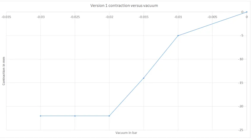
Version 1
With this actuator several issues where identified while testing. First of all since the thickness of the walls is not precisely the same everywhere a slight inhomogeneous motion can be seen. Next to that with the available hardware (vacuum pump, solenoid valves and vacuum pressure regulator) the time to contract more than 5 mm takes more than five seconds. Initial require-ments that were set would need full contraction to be possible in around 1.5 s (full breath cycle would be around 3 s), thus actuation was not quick enough. Contraction versus pressure can be seen in 3.17. The critical pressure is at 0.02 bar.
Version 2
Immediately during the first test it became clear that the chosen dimensions do not work. Due to the ’flattening’ of the actuators the side walls come in contact with each other when deflat-ing the actuator. They do this before the actuator starts actually buckldeflat-ing, this means there is virtually no contraction. This means this design is unusable.
Version 3
Figure 3.17:Average contraction for free contraction of the first version
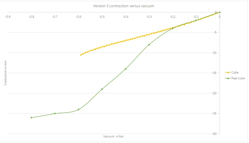
with other literature where Ecoflex 00-30 is used and the critical pressure is around 0.4 bar. With a higher Youngs modulus a higher critical pressure is expected. What can also be said is that the contraction versus pressure curve is more or less linear up until the critical pressure, as was predicted based on previous literature.
Figure 3.18:Contraction versus pressure for version 3 of the actuator. Tested twice for two actuators
3.3.5 Comparison between FEM and characterization
Version 1
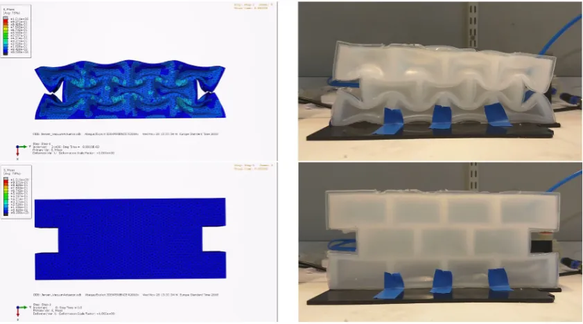
[image:33.595.90.515.412.674.2]Dif-ferences that can be seen are due to the lack of gravity and a pneumatic tube in the simulation. The pneumatic tube causes the real actuator to contract a bit skewed, there is a slight load of the tube on the actuator. Gravity causes the real actuator to contract/buckle more at the bot-tom of the actuator than at the top due to the weight of the actuator itself. Another difference between the simulation and the real actuator is the constraint at the bottom. In the simulation the whole bottom face is constraint. For the real actuator it is not easily possible to do this the same way. Tape has been used to constrain it, without further influencing the motion of the actuator, but as can be seen in figure 3.19 the bottom of the actuator still starts buckling, which is definitely not the case in the simulations.
Figure 3.19:The FE model (left) and real actuator (right) side by side. On top the contracted state and at the bottom the ’relaxed’ state.
Version 2
Both simulation and real testing give the same results. The actuator shows virtually no contrac-tion.
Version 3
Figure 3.20:Data of the contraction versus vacuum for the simulation and real actuator version 3
3.4 Summary and next steps
Three types of actuators have been designed and characterized. For all three designs have been made that behave comparable to previous literature and that can be used in the design of the diaphragm. This design of the diaphragm will be made and explained in the next chapter.
4 Design, production and characterization of the
diaphragm
In this chapter the design, analysis, production and characterization of the diaphragm will be discussed. The diaphragms described here are build up out of the actuators that were intro-duced in chapter 3. The actuators that will be used for the diaphragm are the Pneunet bend-ing actuator and the vacuum actuated muscle inspired structure version 3. The reason the pneumatic artificial muscles are not used in the diaphragm is because the vacuum actuated muscle inspired structures are potentially easier to incorporate into a fully Ecoflex diaphragm. Both the artificial muscles and the vacuum actuated muscle inspired structures would fulfil the same role, thus the vacuum actuator is chosen. The pneumatic artificial muscles will be used to change the orientation of the diaphragm, as will be explained later on.
Furthermore, superelastic material will be used, because it can aid in keeping the diaphragm in shape and it is possible to vary the compliance of the diaphragm with.
The concepts that will be pursued are the ones explained in section 2.7.2, from now on aphragm version 1, as well as the one explained in section 2.7.5, from now on referred to as di-aphragm version 2. Both will be made with and without superelastic material. First, didi-aphragm version 1 is made where it is possible to insert superelastic material in the diaphragm. The step from diaphragm version 1 to version 2 is the addition of vacuum actuators to version 1.
In order to test the diaphragm, a stand is made to support it and a liver phantom is made to be able to test the diaphragm with a realistic load. The stand and liver phantom will also be explained in this chapter. In chapter 5 two models are explained, the characterization on which those two models are based is explained at the end of this chapter.
The requirements that need to be taken into account for the design of the diaphragm, stand and liver phantom are:
• The robot needs to be MR safe and sufficiently MR compatible
– The part that goes inside the scanner bore should not cause artefacts that can ob-scure the region of interest
– The system needs to fit inside a scanner with a bore of 50 cm, which is assumed to be the smallest MRI scanner that is commonly used for this application
• The motion of the liver needs to be accurate
– Between 0 mm to 8 mm in left-right (ML) direction
– Between 4 mm to 14 mm in up-down (SI) direction
– Between 2 mm to 8 mm in front-back (AP) direction with preferably the possibility of creating a difference between left and right
– Frequency that should be achievable is 0.25 Hz to 0.3 Hz
– Optional: taking into account the motion of for example heartbeats
• The set-up will represent a patient in supine position
• The design of the set-up will be inspired by the human anatomy
4.1 Stand
In order to support/hang the diaphragm a stand is necessary. The stand must be able to hold the diaphragm and it needs to have space for the liver phantom. First, the aim is to only focus on SI motion, thus the liver can simply be supported by a plate over which it is sliding. Later on, this support for the liver can be changed to also allow motion in AP and ML direction.
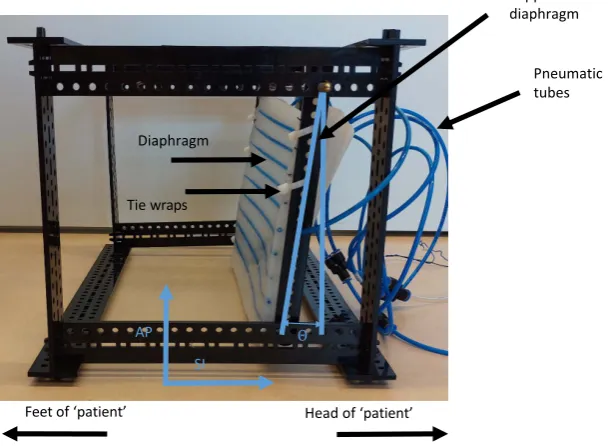
The stand can be seen in figure 4.1, the support plate for the liver phantom and the liver phan-tom itself are not shown there. In that figure also the names of the direction of motion are shown. SI motion is up and down, when a person is standing up right. AP is back and front when a person is up right. Since the stand is representing someone lying down on its back that is rotated 90 degrees, as depicted in figure 4.1. The angle under which the diaphragm is hung can also be seen there, this isθ.
AP SI
Θ
Feetof ‘patient’ Head of ‘patient’
Diaphragm
Pneumatic tubes Support of the diaphragm
[image:37.595.147.453.258.481.2]Tie wraps
Figure 4.1:The designed stand with the names of the directions of motion
The stand has been made such that it can be produced quickly and the diaphragm, wiring and tubing can be attached to it. Next to that it is made such that dimensions can quickly be changed and it is already MRI compatible, apart from one brass rod, which is used to attach the support of the diaphragm to. This should still be changed before the stand goes into a MR scanner. It is made from Delrin of 4 mm thick from pieces that can be laser-cut. The connector pieces are all such that they can be assembled without tools, useful when assembly has to be done near an MRI scanner. Next to that it is possible to put the stand together in different configurations. Along every stud holes have been made such that wiring, tubing etc. can be attached there.
The diaphragm will be attached to the stand with help of tie wraps. As this allows for the di-aphragm to be attached and detached easily and also in different ways if necessary. This can also be seen in figure 4.1.
4.2 Liver phantom
compatible. To make this the same mold has been used as for the aforementioned projects. The weight (approximately 1300 g) and shape are correct, the elasticity is not, but for the testing that is neglected. The fact that the weight is the same as for a real liver means that this allows for comparable loads on the diaphragm. The gelatin liver with the right elasticity and the Ecoflex liver with the right weight can be seen in figure 4.2.
Gelatin liver Ecoflex liver
Figure 4.2:On the left te gelatin liver on the right the Ecoflex liver, both are made with the same model. Elasticity and weight differ between the two.
4.3 Design, analysis and production of the diaphragm
4.3.1 Diaphragm version 1
The first iteration of the diaphragm only contains the Pneunet bending actuators. These are placed with an equal spacing across the diaphragm (see figure 4.6). The diaphragm consists of a 5 mm thick sheet of Ecoflex 00-50 of approximately 200 mm×337 mm. Inside that sheet inserts are made such that nitinol wires can be easily inserted and removed. A schematic drawing of this can be seen in figure 4.3. The diaphragm will be free on the top and bottom to move, but will be attached to the stand on the left and right side. When looking at the top view, the middle diaphragm will move downwards when the actuators are actuated.
337 mm
200 mm 5 mm = Pneunet bending actuator
= Insert for nitinol wire
= Ecoflex sheet
Top view
[image:39.595.105.503.87.315.2]Back view
Figure 4.3:Schematic drawing of version 1 of the diaphragm, this is the diaphragm in unactuated state. The Pneunet bending actuator will bend the diaphragm into a dome shape. The nitinol wire will add some elasticity to the diaphragm which should help it flatten again.
[image:39.595.90.516.383.608.2]Figure 4.5:The deflection of the middle of the diaphragm. One is where both sides are constrained and the other one is where just one side is constrained, this is the situation in figure 4.4.
Figure 4.6:The mold for the sheet/bottom of the diaphragm. The bending actuators are on top of the sheet of Ecoflex. There are pneumatic tubes in the diaphragm to easily insert and remove nitinol wire. Rods are in the mold to keep the pneumatic tubes in place in the diaphragm, this will be extracted once the sheet of Ecoflex is cured
4.3.2 Diaphragm version 2
The second version of the diaphragm is same as the first version with the addition of the vac-uum actuated muscles inspired structures. These will be inserted between the three bending actuators that are already present. A schematic drawing of this can be see in figure 4.7. This is actually version 1 of the diaphragm that will be used again, thus after version 2 is made, version 1 cannot be tested anymore.
337 mm
200 mm 5 mm = Pneunet bending actuator
= Insert for nitinol wire
= Ecoflex sheet
= VAMP
Top view
Back view
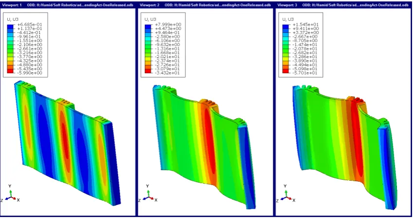
[image:41.595.102.503.488.713.2]Based on simulations that were performed it has been determined to attach the vacuum ac-tuators both to the bending acac-tuators and the diaphragm underneath it. This will lead to less ’curling/folding’ of the diaphragm underneath the vacuum actuators resulting in a more nat-ural shape, comparable to the actual human diaphragm. This can be seen on the left in figure 4.8. On the right in that figure the actuators are only attached to the bending actuators.
Figure 4.8: Version 2 of the diaphragm in simulation. From top to bottom, pressure is applied to the bending actuators and at the end a vacuum is applied to the vacuum actuators. Difference between left and right is that on the left the vacuum actuators are completely attached to the diaphragm and on the right they are only to the bending actuators.
Figure 4.9:Version 2 of the diaphragm being fabricated. The vacuum actuators, in this figure a vacuum is applied to them, are still not completely attached to the bending actuators. This can be seen at the red arrows. That is fixed by adding more uncured Ecoflex at those position
4.4 Testing
In order to see what is possible with the diaphragms both versions of the diaphragm have briefly been tested to see what motion can be achieved and what the limits are. This is done to determine which version will be characterized further and whether more improvements to the diaphragm, stand of liver phantom are necessary to comply to the requirement set in section 2.1. In order to do this testing and the characterization later on a small Matlab application has been written that can control the pressure regulators via an Arduino to actuate the diaphragm. The user interface of this application can be seen in figure 4.10.
Figure 4.10:The matlab application to easily control the pressure regulators while testing. Also a ’rudi-mentary’ breathing loop can be set with this application.
4.4.1 Diaphragm version 1
in the middle of the diaphragm. This has been tested with and without nitinol wires inserted into the diaphragm.
The results of this can be seen in figure 4.12. It is clear from this that the motion is in agreement with the requirements set for the SI motion (between 4 mm and 14 mm). At the maximum pressure, a motion of 25 mm can be seen for the diaphragm without nitinol and of 22.5 mm for the diaphragm with nitinol. This motion is reproducible within a range of 1 mm. This is in the same order of magnitude as could be seen during the test with the single bending actuator, where the unloaded case showed a displacement of almost 20 mm.
[image:44.595.134.436.391.619.2]Later tests have been done with an EM-tracker. The tracker has been placed on 3 locations on the diaphragm which can be seen in figure 4.11. This allows for tracking those points on the diaphragm in 3 dimensions instead of 1 dimension as was the case with the tray. While doing this the diaphragm was hung differently in the stand. The bottom attachment to the stand was slightly higher then in previous tests, which made sure the diaphragm was never touching the bottom plate. This gave different results. With nitinol wire inserted a motion of 18 mm could be seen and without nitinol a motion of 15 mm could be seen at 0.12 bar. This shows how much influence the constraints of the diaphragm have on the motion. Both with and without nitinol a change of 8 mm maximum motion can be seen, without any changes to the diaphragm. These results can also be seen in figure 4.12. Over the whole pressure range larger motion can be seen due to the fact that the diaphragm was not touching the plate underneath it anymore. With the EM-tracker the measurements have been stopped at 0.12 bar as ballooning became an issue when kept longer at a higher pressure. This was previously not an issue, hence data for a higher pressure for the test with the tray.
Figure 4.11:The diaphragm has been attached to the stand and an EM tracker has been attached to the diaphragm in order to track its motion in 3D. In this figure also the support plate for the liver can be seen. This is right in front of the diaphragm
im-Figure 4.12:Testing of diaphragm with and without the nitinol. All pneunet actuators are actuatated with the same pressure at the same time.
proving diaphragm version 1 and the stand, which would have been an option, the decision was made to make version 2 of the diaphragm. The addition of the vacuum actuated muscle inspired structures can help generating more force, allowing for the phantom liver to be moved significantly.
4.4.2 Diaphragm version 2
The motion of version 2 has only been measured with the EM tracker. The approach was the same as for version 1. First measure the displacement of the unloaded diaphragm when ac-tuating all bending actuators the same simultaneously. This should cause positive SI motion with a positive pressure. For negative SI motion the vacuum actuators are actuated. This is again measured on the same three points on the diaphragm, where position 1 is again most interesting as the biggest motion is expected there. These results can be seen in figure 4.13. What can clearly be seen is that motion becomes linear with addition of the vacuum actuators to the diaphragm. Due to an error in the set-up data for the vacuum actuator is not there for intermediate values. What can be said here is that motion in positive direction is slightly less with the vacuum actuators, but overall motion becomes larger. With nitinol around 28 mm and without nitinol round 40 mm. The nitinol seems to have a bigger influence on the vacuum ac-tuator motion than the bending acac-tuator motion, because in version 1 the difference was less clear then for version 2. The conclusion is that the SI motion has become 1.5 to 2.5 times larger when comparing version 2 to version 1 and that SI motion is well within the desired range of 8 mm to 14 mm.
[image:45.595.91.516.76.343.2]