MIMO Wavelet Transform using Optimized Successive
Interference Cancellation
Rameez Asif
Faculty of Engineering and Informatics, University of Bradford Bradford, West Yorkshire
BD7 1DP, U.K.
M. S. Binmelha
Faculty of Engineering and Informatics, University of Bradford Bradford, West Yorkshire
BD7 1DP, U.K.
Raed Abd-Alhameed
Faculty of Engineering and Informatics, University of Bradford Bradford, West Yorkshire
BD7 1DP, U.K.
J. M. Noras
Faculty of Engineering and Informatics, University of Bradford Bradford, West Yorkshire
BD7 1DP, U.K.
ABSTRACT
This research introduces a physical layer technique to enhance the capability of MIMO wavelet systems by using successive interference cancellation which enables the receiver to decode simultaneous data packets. The received power of the data packet was introduced to further optimize the receiver’s decision capability. Results show that a Discrete Wavelet Transform-based MIMO system with interference cancellation provides a performance gain as compared to a theoretical 2x2 MIMO channel in terms of BER vs. SNR performance. The performances of two different techniques have been evaluated in this work using interference cancellation both with and without consideration of received signal power.
Keywords
OFDM, Wavelets, DWT, WPT, Zero-Forcing, Minimum Mean Squared Error.
1.
INTRODUCTION
Wavelet transforms provide an alternative to the Discrete Fourier Transform (DFT) used in Orthogonal Frequency Division Multiplex (OFDM) multicarrier transmission. When compared to conventional single-carrier systems, multicarrier systems have the well-known advantage that they reduce inter-symbol interference (ISI) caused by the channel delay spread in high data-rate transmission. In a multicarrier system, multiple high data-rate serial streams are divided into a number of lower rate parallel streams [1]. With a fixed overall bandwidth, an increased number of sub-channels means lower bandwidth and hence lower data-rate in each sub-channel, resulting in longer symbol periods with reduced susceptibility to channel delay spread and related ISI. Alternatively, this can be viewed as making the sub-channel bandwidth small compared to the coherence bandwidth of the channel [2].
Wavelet-based systems can provide all the conventional advantages of OFDM systems and can help improve the PAPR, sensitivity to carrier frequency timing offset and overall Bit Error Rate (BER) performance of the system [3]. The ISI produced in the wavelet-based multi carrier system (MCS) can be divided among different wavelet symbols, thus becoming easily correctible at the receiver. Insertion of a cyclic prefix (CP) or a guard band is not required in such systems as they maintain orthogonality using perfect reconstruction quadrature mirror filter banks (PRQMF). Due to the energy containment in the main lobe of the wavelet symbol, these symbols have strongly suppressed side lobes providing them with high spectral density and reducing inter-carrier interference (ICI). Moreover, the sub-channel in this transform is compact which increases the probability of
correct bit decoding. Basis sets of this transform use time-frequency partitioning, which in turn provides SNR performance gain [4].
To make more reliable and efficient systems with higher data-rate and increased coverage, Multiple Input Multiple Output (MIMO) has been used to create multiple channels in space (spatial multiplexing) without requiring additional bandwidth. MIMO-based systems are superior to Single Input Single Output (SISO) systems in terms of their spectral efficiency and they require less transmission energy to match a given throughput for any given BER.
The three main contributions of this work are 1) to enhance the capabilities of wavelet MIMO systems, optimizing their potential use in next generation wireless communication systems, which will require about 1 Gb/s transfer rates, and 2) to permit efficient use of the frequency spectrum without the bandwidth wastage due to the CP insertion. Depending on the system design, the CP can waste up to a quarter of the total bandwidth.
The final main contribution is to propose the best equalization and data recovery technique for wavelet-based systems, since without a CP these symbols go through time domain convolution with the channel introducing an irreducible error. It was said in [9] that if the coefficients from the noisy wavelet signal are used for channel equalization rather than the original transmitted signal they can produce large estimation errors since longer wavelet filter sequences are required. No previous published work has contributed to the study of this problem in wavelet-based systems.
Successive interference cancellation (SIC) and optimized successive interference cancellation (OSIC) physical layer techniques use zero-forcing (ZF) and minimum mean squared error (MMSE) equalization algorithms to increase the accuracy of equalization at the receiver, using the received signal strength at the receiver. Both techniques provide a marginal gain in terms of BER performance when compared to a theoretical 2x2 MIMO channel and can provide much bigger performance difference than practical systems.
This paper has been organized as follows; the basics of wavelet transforms are described in Section 2, followed by the DWT baseband architecture in section 3, system model in section 4, channel equalization methods in section 5, simulation results in 6, followed by the conclusions.
2.
WAVELET TRANSFORM BASICS
scaling into approximate GL,n and detailed Hm,n coefficients.
This relies on the concept of embedded vector spaces
(1)
If a vector space VT consists of subspaces VT-r these
subspaces can be referred to as decomposed signal spaces, so the multiply-resolved components of our total original vector space can be shown as in Fig. 1.
In [5] VT-r is being mathematically defined using a dilation
equation as;
(2)
Once this dilation takes place the original vector space of the signal gets divided, and by using Equation 2 the low frequency component can be extracted through a half-band low-pass filter g(n) which will have half the bandwidth as compared to the original signal as implied by the dilation factor 2 used in Equation 2. The same can be done for the high frequency component, using a half-band high-pass filter h(n), which can be mathematically stated as:
(3)
VT
VT-1
VT-2
[image:2.595.312.544.113.493.2]VT-r
Fig 1: Multiply-resolved vector spaces
Equations 2 and 3 can be further solved to determine one of the infinite sets of wavelet basis functions. Once the low-pass filter coefficients are extracted the relation in Equation 4 can be used to extract the high-pass filter coefficients to construct the PRQMF filter bank:
(4)
where L stands for the filter length and n is the filter coefficient. The continuous wavelet transform of a signal x[n] over the vector space T can be written as;
T
, CWT
(
,
)
x
(
n
)
(
t
)
dt
X
(5)where is the scale and is the shift. The transform in its continuous form requires extensive analytical solution and no viable practical inverse exists so it is important to discretize it which also produces an error when an infinite sequence is squeezed to finite length and can be mathematically written as [6]:
(6)
where m represents the scale and n represents the shift. The discretized signal composed of its constituent approximation and detail parts can be written as [7];
(7)
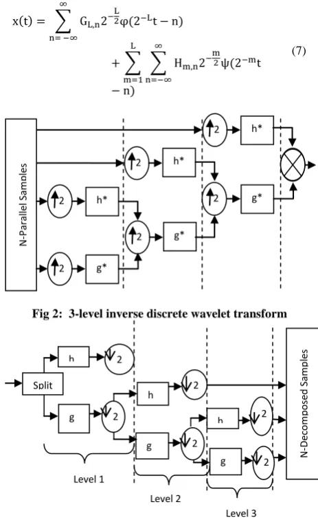
Fig 2: 3-level inverse discrete wavelet transform
Fig 3: 3-level discrete wavelet transform
3.
THE DWT BASEBAND
ARCHITECTURE
Once the data is discretised the input signal can be analysed in different frequency bands by decomposing it into an approximation part, GL,n, and a detail part Hm,n. This
decomposition takes place for every shift and scale. It is to be noted that when the DWT is employed GL,n is the only part
thatgets iteratively decomposed which means that the second half of Equation 4 is absent and the total number of sub-channels that can be considered for multiplexing will equal M = log2(K) + 2. K stands for the number of decomposition
levels and M represents the resultant sub-channels in each level.
4.
SYSTEM MODEL
A two transmit- and two receive-antenna based MIMO system was formed, which will be used to model the transmission of the data stream. The data stream is divided and arranged as two sets of symbols in each time slot for both the antennas, which enables to double the data-rate by reducing the total number of time slots by half, when compared to a one-transmit-antenna system.
Level 3 Level 1
Level 2 2 2
g 2
h
2 2
2 h
g h
g Split
N
-D
ec
o
m
po
se
d
Sam
pl
es
2 h*
2 h*
2 g*
g*
+
N
-P
ar
al
le
l Sam
pl
es
2
2 h*
[image:2.595.94.264.334.493.2]4.1
Multipath Propagation Environment
The channel environments used was Rayleigh multipath with Additive White Gaussian Noise (AWGN) and each transmitted stream encounters an independent multipath. When a multipath environment is present there will be a train of impulses received at the receiver for every transmitted impulse. The band-pass signal can be written mathematically as [8]:
(8)
where denotes the baseband signal, represents the real part, is the carrier frequency and time is t. The received signal after travelling through the multiple path channel where the attenuation of the kth path is and time delay is , can be mathematically described as:
y(t) = . (9)
Substituting Eq. (8) into Eq. (9) yields
(10)
The baseband equivalent of the received signal has a mathematical form:
(11)
where represents the phase of the kth path and the impulse response is written as:
(12)
4.2
Rayleigh Fading Environment
Assuming a total of k paths, the central limit theorem can be applied and each path can be modelled as circularly symmetric complex Gaussian random variable:
(13)
Time is the variable quantity. Equation 13 shows that both the real and imaginary parts are zero-mean independent and identically distributed random Gaussian variables. For
(14)
the statistics of Z can be satisfied by the variance as:
(15)
The quantity represents the Rayleigh random variable. This is the most practical dynamically changing channel model.
5.
CHANNEL EQUALIZATION
METHOD
A transmitted signal convolved in the time domain with a channel with no cyclic prefix gives rise to an irreducible ISI error. Thus, it is important to note that the signal will not only be corrupted by the channel impairments and noise but will also be corrupted by the ISI.
5.1
Zero Forcing, SIC and Optimization
When transmitting using a 2×2 MIMO scheme the total number of channels that exist between the transmitter and receiver are four, where channel h1 exists between tx1 and rx1,
h2 exists between tx1 and rx2, h3 exists between tx2 and rx1 and
h4 exists between tx2 and rx2. x1 and x2 are the transmitted
symbols in time slot 1 for each antenna. This means that h1
and h2 will convolve with x1 and x2 with the addition of noise
and ISI resulting in y1 and same is true for h3 and h4 which
will result in y2.
(16)
(17)
(18)
So, in the zero forcing linear detector, , can be modelled as:
(19)
Multiplying Equation 18 with received signal matrix will provide the estimated transmitted signal.
(20)
Now, the receiver can arbitrarily choose one symbol, in this case and subtract its effect from the received signal
vectors y1 and y2 i.e.
(21)
The same procedure as in Equation 20 can be done for .
(22)
Once r is successfully extracted, it can be combined using Maximum Ratio Combining (MRC) as the system is now similar to one transmit two receive antennas and the receiver diversity can be used to combine the information.
For optimization, signal power can be used which can be calculated as:
(23)
and
(24)
5.2
MMSE Equalization
In MMSE equalization the main step is to derive the equalization coefficients k[i] for each sampling instant [i] which can be used to reduce the error between the original transmitted signal and the estimated received signal k[1]×r[1]. Mathematically it can be shown [9];
(25)
(27)
(28)
where at any sampling point the error introduced (i) is , k represents the equalization coefficients and the received samples are denoted as r. R shows the cross- and auto-correlations between the sequences. To decipher for MMSE, k is required that will reduce to a negligible value. Differentiating Equation 28 with respect to k and setting the result equal to zero will provide the minimal error rate coefficients:
(19)
After solving the above equation
(20)
adding to both sides of the equation and then dividing by provides the required equalization coefficients k as;
(21)
6.
SIMULATION RESULTS.All the simulations have been performed using Monte Carlo simulations with following parameters as in Table I:
6.1
Successive Interference Cancellation
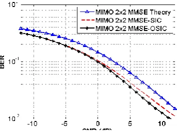
[image:4.595.309.548.209.419.2]In the first simulation only the ZF-SIC technique has been used where the receiver can choose any symbol it likes and ignore the other one which in turn makes the whole system exactly like one transmit two receive antennas. Maximal ratio combining was then employed to efficiently combine the information. Results produced by such a system are shown in Figure 4.
NOTE: The results are compared to theoretical results for accuracy
The SIC provides a marginal performance gain of about 0.2 dB at low SNR compared with theoretical values which is not significant enough but if real life practical systems are considered it will be a great performance improvement, but still to optimize the algorithm further the signal power in addition to SIC was employed to see the performance gain after optimization.
Fig 4: DWT-MIMO-MCS using ZF-SIC
6.2
Optimized Successive Interference
Cancellation
In this method, the power of the received signal has been considered for more accurate prediction of which symbol to keep. The results for the study are shown in Figure 5. Comparing both Figure 4 and Figure 5 it is evident that even though it is assumed that the channel is known at the receiver, the ZF equalizations gives rise to extra noise which makes it hard to predict the correct symbol. Thus, this technique with ZF equalization does not provide satisfying results.
TABLE 1: Simulation Parameters
Transform DWT
Symbol Length 106 x 26
Modulation BPSK
Channel Rayleigh Flat Fading Multipath With AWGN Wavelet Family and Filter Order Daubechies 8
Combining Technique MRC
Fig 5: DWT-MIMO-MCS using ZF-Optimized-SIC
6.3
MMSE Equalization using SIC and
OSIC
[image:4.595.343.520.520.652.2]To further study and differentiate between the performances of Zero forcing equalization that gives rise to added noise also MMSE was implemented both with and without OSIC and the results are shown in Figure 6.
Fig 6: DWT-MIMO using MMSE with successive interference cancellation and optimized successive
interference cancellation
[image:4.595.90.247.624.743.2]6.4
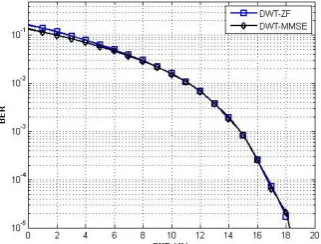
MMSE VS. ZF in SISO DWT-MCS
[image:5.595.89.250.191.313.2]In the simulation results shown below it can be seen that the performances of both equalization techniques match each other. This is because the noise term addition in the ZF algorithm, even though the channel is known, reduces the BER performance. So, the MMSE equalization which conventional OFDM theory suggests should perform better than ZF does not. This is due to ISI produced by the channel signal linear convolution which increases the error in the equalization coefficients for MMSE.
Figure 7: ZF and MMSE in SISO-DWT
7.
CONCLUSIONS
In this work, a wavelet-based multicarrier system using a MIMO 2x2 scheme was proposed to optimize the performance of wavelet-based systems and to increase the overall system reliability, data-rate, spectral efficiency and optimized use of the bandwidth provided. These systems do not have the constraints of guard time insertion because even though the signal is distorted when passed through the channel this does not affect the orthogonality which is maintained using the PRQMF bank. Wavelets are more appealing because of their improved SNR performance as compared to the conventional FFT OFDM system because the signal energy containment in the main lobe and suppressed side lobes. The MIMO scheme allows the data-rate to be doubled as the timing slots required for the transmission of a given sequence are reduced by half because the symbols can be transmitted in pairs.
Equalization of wavelet symbols, removal of noise and correct symbol prediction is also a problem: it is shown that OSIC when employed with MMSE equalization will produce the
best results. A comparison of MMSE and ZF has also been presented to show that both equalization algorithms show equal performance in SISO wavelet-based MCS but when the MIMO-OSIC and MIMO-SIC is employed MMSE outperforms ZF because no added noise is produced which makes it easy to predict the correct signal.
8.
REFERENCES
[1] H. Hosseini, S. K. B. S. Yusof, N. Fisal and A. Farzamnia, "Wavelet Packet-Based Transceiver for Cognitive UWB," in Canadian Journal of Electrical and Computer Engineering, vol. 37, no. 2, pp. 59-64, Spring 2014. doi: 10.1109/CJECE.2014.2312451
[2] Andrea Goldsmith, Wireless Communications, Cambridge University Press, (2005).
[3] R Asif, Raed Abd-alhameed and J M Noras, “A Unique Wavelet-based Multicarrier System with and without MIMO over Multipath Channels with AWGN” International Journal of Computer Applications, vol. 117, issue 9, May 2015, pp. 31-40, ISSN: 0975 – 8887, DOI: 10.5120/20585-3015
[4] R. Asif, R. A. Abd-alhameed, “Performance Evaluation of DWT-OFDM and FFT-OFDM for Multicarrier Communications Systems using Time Domain Zero Forcing Equalization”, International Journal of Computer Applications, vol. 51, no.4, August 2012, pp. 34-38. ISSN: 0975 – 8887.
[5] M. Vetterli and C. Herley, “Wavelets and Filter Banks: Theory and Design.” IEEE Transaction on Signal Processing, Vol.40, N0.9, pp.2207 – 2231, Sept. 1992. [6] I. Daubechies, “Ten lectures on wavelets,” Society for
Industrial Mathematics, Vol. 61, 1992.
[7] E. Vlachos, A. S. Lalos and K. Berberidis, "Low-Complexity OSIC Equalization for OFDM-Based Vehicular Communications," in IEEE Transactions on Vehicular Technology, vol. 66, no. 5, pp. 3765-3776,
May 2017.
doi: 10.1109/TVT.2016.2598185
[8] D. Tse and P. Viswanath, “Fundamentals of Wireless Communication.” Cambridge University Press, 2005. [9] Yong Soo Cho, et al., Mimo-OFDM wireless