ISSN Online: 1945-3124 ISSN Print: 1945-3116
Nesting and Berth Allocation by an Expert
System Using Heuristic Search
Dongmok Sheen
1, Yoonho Seo
2*1School of Naval Architecture and Ocean Engineering, University of Ulsan, Ulsan, Korea
2School of Industrial Management Engineering, Korea University, Seoul, Korea
Abstract
Nesting is a common problem in industries such as shipbuilding, auto-maker, clothing, shoe-making, and furniture, in which various parts are cut off from a stock or stocks while minimizing the wastes or maximizing the utilization of the stock. Berth allocation at seaside is also considered one form of two di-mensional nesting problems, in which a ship is assigned a location for service during a certain time slot. This paper presents an expert system using a heu-ristic search method for nesting problems. The parts and stocks are represent- ed by pixels with which utility function is used to evaluate current state in search tree. The system is developed in CLIPS, an expert system shell and ap-plied to various example problems with different constraints and to a berth allocation example to illustrate its applicability under different conditions.
Keywords
Nesting, Berth Allocation, Heuristic Search, CLIPS
1. Introduction
Nesting can be defined as a problem of packing various shapes as close as possi-ble in a limited space in order to minimize the wastes. Cutting parts from raw planar materials in shipbuilding, automobiles, furniture, shoes, clothing, and paper companies, or storing parts in space are some example nesting problems. Since nesting is an NP-complete problem [1], heuristics are used in solving the problem. Shapes are usually sorted first by size and then approximated as simple convex polygons with which algorithms such as NFP (Nofit Polygon) [2] are used, or represented as pixels with which algorithms such as BLF (bottom-left filling) algorithm [3] [4] are used. In special application such as laser cutting, minimization of cycle time by optimal cutting sequence as well waste is also considered [5].
How to cite this paper: Sheen, D. and Seo, Y. (2017) Nesting and Berth Allocation by an Expert System Using Heuristic Search. Journal of Software Engineering and Ap-plications, 10, 311-323.
https://doi.org/10.4236/jsea.2017.104018
Received: February 14, 2017 Accepted: April 3, 2017 Published: April 6, 2017
Copyright © 2017 by authors and Scientific Research Publishing Inc. This work is licensed under the Creative Commons Attribution International License (CC BY 4.0).
Spatial scheduling is another well-known nesting problem in which one axis is time. Three-dimensional spatial scheduling, where a part is represented as a prism with service time as height, minimizing make span at block assembly shop is reported [6]. Reference [7] used genetic algorithm to solve a two-dimensional spatial scheduling problem for blocks with growing lengths as assembly progre- sses at pre-erection area in shipbuilding. Berth allocation problem is a two-di- mensional spatial scheduling problem for seaside operations planning, in which a berth is allocated for each ship to load and unload freight within a specified service time [8].
This paper presents an expert system utilizing heuristic search to solve 2-di- mensional nesting problems with different constraints and a berth allocation problem. Expert system approach is used for nesting and berth allocation prob-lems since they have discrete number of possible solutions and the performance can be improved at implementation stage. Compared with algorithmic approa- ches, the performance of the system can be improved by easily adding new rules at implementation stage. For berth allocation problem, for instance, we can add more rules depending on the situation of the quay and scheduling rules.
2. Backgrounds
In order to solve nesting problems, shapes to be nested are usually represented by pixels or approximate polygons. It is easy to represent shapes in pixels and the overlapping between shapes can be easily checked, but they require lots of memory and computing time to represent the shapes accurately. On the other hand, the methods based on approximate polygons need less memory to store data for edges and vertices of polygons, but algorithm for checking overlaps be-comes complicated.
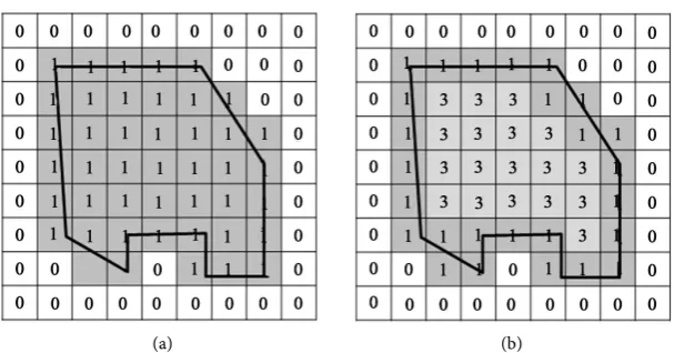
When pixels are used, after defining the resolution, a shape is represented by an enclosing rectangle(ER). Usually the boundary and inside the shape are represented by “1” values while the other part of ER is represented by “0” values as in Figure 1(a) [4]. Some researchers assign different values for the pixels on boundary than the ones inside (Figure 1(b)) so that the types of overlapping (boundary-boundary, boundary-inside, or inside-inside) between two shapes can be easily identified [1] [3]. In pixel-based approaches, BLF algorithm [3] [4]
is frequently used. It scans vertically from the left bottom pixel to the top pixel and then repeats from the right adjacent pixel at the bottom to the top until they find an empty space for the shape to be assigned. Among the approaches based on approximate polygons, NFP algorithms [2] are well known. Figure 2 illu-strates an NFP method. When polygon B moves along the edges of polygon A, the trajectory of a particular point P of B becomes NFP, NAB. When we lay shape B at a position, if P of B enters inside the NAB, it means the shape B over-laps the shape A. When there are concave shapes or shapes with holes, NFP al-gorithm becomes complicated.
(a) (b)
Figure 1. Pixel representations. (a) Binary pixels; (b) Pixels having different values inside.
Figure 2. Nofit polygon.
Nesting on blank with irregular boundaries is another research topic [2] [9] [10]. In shipbuilding industry, the parts with the same height are grouped to-gether and cut from a flat bar to manufacture blocks [11]. This condition makes the problem easier since the number of possible positions is greatly reduced and only 4 configurations of a part (0˚, 180˚, and their mirroring shapes) need to be considered. In Lee and Park’s research, the parts are sorted first by size in des-cending order and then each part is added to the layout in that order. Since sim-ilar parts are abundant in shipbuilding, Lee et al.[12] paired parts in an effort to simplify the nesting algorithm.
Berth allocation problem is to assign the vessels needing services at specific time-windows at specific locations at quay. It is different from general nesting problem in that each shape is rectangle (“service time x length”) with Earliest start time (ES) and Latest finish time (LF), between which the shape must be lo-cated. Problems can be categorized depending on the nature of arrival time, ser-vice time, type of quays, etc. Usually vessel’s length, draft, expected time of ar-rival, and service time are given. The layout of quay can be discrete in which vessels can only be assigned at discrete positions, continuous in which vessels can be assigned any positions, or hybrid [8]. A quay may have several water depths to accommodate ships with different drafts. Multiple quays are also con-sidered in allocating berths [13].
[image:3.595.297.448.261.371.2]concave shapes, but they require lots of memory for accuracy. Approximate po-lygon methods are efficient for convex shapes but it becomes complicated for concave shapes. Expert systems can be a useful nesting tool in that it can easily adopt different types of constraints depending on the application domains and its performance can be easily improved without re-coding as more rules are added.
3. Nesting Expert System
3.1. Data Structure
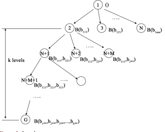
In this research nesting is done by an expert system using heuristic search. The shapes are represented by pixels. Figure 3 shows a search tree used in this re-search. Each node represents a state of layout and as level deepens by one the number of shapes laid increases by one. The root node represents the blank state. At the goal node the number of shapes equals to the number of shapes to be laid. At each node a child node having the maximum value of utility function, which evaluates a node’s likelihood of success, is open. One node can have mul-tiple children nodes depending on the number of shapes and their positions, and orientations including mirroring images. In Figure 3, bijk denotes the i-th part, at
the j-th position with the k-th orientation. Even though each part can have infi-nite number of orientations plus their mirroring images provided the problem domain does not differentiate the front from the backside, the number of orien-tations is limited to reduce the solution space. The nodes with duplicate orienta-tions due to symmetry are not created.
Nr (x) number of children nodes are created at node x for the r-th shape to be
laid on the board B(b1**, b2**,…, br-1**) on which (r-1) shapes are already laid.
Eq-uation (1) shows the number of children at node x where np, no are the number of possible positions and orientations for br, and B (b1**, b2**,…, br-1**) is denoted
[image:4.595.240.507.513.726.2]as Br-1 (x).
( )
1 1(
1( )
)
(
)
0, if overlaps
, where ,
1, otherwise p o
n n
r i j rij r
b B
N x = =chk b B− x chk b B
= =
∑ ∑
(1)The following shows the templates of a shape and a node written in CLIPS. A shape has sister patterns created by its orientations, which are stored in the slot orientation. A node keeps a list of shapes already assigned in tile-list with their orientations, positions (row, col) in tile-orient-list, tile-position-row, and tile- position-col which correspond to the subscript of bijk in Figure 3. Therefore, tile-
list, tile-orient-list, tile-position-row, and tile-position-col are empty at root- node.
(deftemplate MAIN::tile
(slot tile-id (type NUMBER)) (slot cardinality (type NUMBER))
(multislot orientation (type FACT-ADDRESS))) (deftemplate MAIN::node
(slot node-id (type NUMBER)); natural number (slot parent (type NUMBER)); If it is 0, no parent (multislot tile-list (type FACT-ADDRESS)) (multislot tile-orient-list (type FACT-ADDRESS)) (multislot tile-position-row (type NUMBER)) (multislot tile-position-col (type NUMBER)))
The representation of a shape differs depending on the applications. The shapes are represented in pixels for general nesting problems. In berth allocation problems, however, only dimensional properties are stored since the shapes are rectangles with length of ship as width and service time as height. The orienta-tions of shapes are not considered. Instead, the properties such as ES, LF, service time, and length are stored. The following shows the templates of a shape and a node for berth allocation problem written in CLIPS. A shape does not have sister patterns since orientation is not considered, but has the length of the vessel in length, service time in duration, ES, and LF. Therefore, a node does not have tile-orient-list slot as in general nesting problem for orientations of shapes al-ready assigned.
(deftemplate MAIN::tile
(slot tile-id (type NUMBER)) (slot length (type NUMBER)) (slot duration (type NUMBER)) (slot ES (type NUMBER)) (slot LF (type NUMBER))) (deftemplate MAIN::node
(slot node-id (type NUMBER)); natural number (slot parent (type NUMBER)); If it is 0, no parent (multislot tile-list (type FACT-ADDRESS)) (multislot tile-position-row (type NUMBER)) (multislot tile-position-col (type NUMBER)))
open-list keeping the ordered list of nodes to open.
3.2. Rules
Rule base consists of rules and the functions related. Rule: initialize sorts shapes by size in descending order. It also creates sister patterns of shapes generated from different orientations and mirroring. The following shows a pseudo-code of Rule: initialize.
Rule: initialize IF (initial-condition) THEN
Read shapes and call it {s}
Sort shapes by size in descending order, and call it {s*} Create a root node, and call it n0.
Let open-list = {n0}
Rule: open-node is the basic rule to expand the search tree. It gets the first node in open-list and opens it. The children nodes are created and added to open-list as it is open. When adding the children nodes to open-list, they are sorted by the value of utility function and added to the front of open-list to ena-ble depth-first search. The following shows a pseudo code of Rule: open-node.
Rule: open-node
IF open-list == {ni, REST}
THEN
Expand the node ni and save the result as {N}.
Sort N in descending order of utility function value and save it as {N*}. Update the set open-list by prepending N* to REST.
Let open-list = {N*, REST}
The following shows the condition part of Rule: open-node rule written in CLIPS. CLIPS use pattern matching in finding the applicable rules at current state.
(defrule MAIN::open-node
?op <- (open-list (nodes ?nid $?rest-n))
?cn<- (node (node-id ?nid) (parent ?p) (tile-list $?tlist)
(tile-orient-list $?torlist) (tile-position-row $?prlist) (tile-position-col $?pcl-ist))
(lay-tile-list $?tlist ?t $?rest-t) => ….)
where the function count() counts the number of pixels. Br-1(x) is current layout
at node x, br** indicates the rth shape at certain position and orientation.
( )
(
r1 , r**)
bk** Br1( )x(
( )
k**( )
r**)
u B− x b =
∑
∈ − count MER b ∩MER b (2)The bigger value of utility function means that there are more possibilities for shapes to be closely packed and therefore to get better solution. In calculating the utility function, the four corners of the shape can be easily calculated by off-setting the position. The following pseudo code shows the count function, where (xi,yi) and (xip,yip) are the locations of the upper-left corner the lower-right
cor-ners of MER of shape i. In Figure 4, count function counts the number of over-lapping pixels, shown in grey color, between two MERs.
Function: count(bi**, bj**)
If (xj ≤ xip) ∧ (xi ≤ xjp) ∧ (yj ≤ yip) ∧ (yi ≤ yjp)
width = min(xip,xjp) - max(xi,xj) + 1
height = min(yip,yjp) - max(yi,yj) + 1
return width * height else
return 0
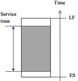
[image:7.595.289.455.444.546.2]In berth allocation problems, all shapes are rectangles with service time and the length of vessel as height and width respectively. Figure 5 shows a shape in berth allocation problem. Therefore, overlapping between MERs is not allowed. Instead, nodes are sorted by ES in ascending order, by length in descending or-der, and by LF in ascending order to minimize make span and to maximize the utilization of quay area.
Figure 4. Graphical representation of the evaluation function.
[image:7.595.313.438.581.711.2]Rule: goal checks if the goal state is reached. The following shows the condi-tion part of the rule in CLIPS. The goal node is reached if the number of shapes ($?tlist) to be laid equals to the number of shapes already laid.
(defrule MAIN::goal
?open <- (open-list (nodes ?nid $?list)) (lay-tile-list $?tlist)
(node (node-id ?nid) (tile-list $?tlist) (tile-orient-list $?torlist) (tile-position-row $?prlist) (tile-position-col $?pclist)) => …)
4. Example Problems
4.1. Nesting Allowing Mirroring and Rotations
This example is a general nesting problem in which eight sister patterns (four orientations and their mirroring patterns) for each shape are considered. At ini-tial stage, maximum of eight sister patterns are created for each shape without duplicates. At every node, children nodes are generated for a part for possible positions with all sister patterns are considered to lay the part. The children nodes are sorted in descending order of the values of the utility function shown in Equation (2). Figure 6 shows the result of nesting on 35 × 20 size blank.
[image:8.595.257.491.435.715.2]It is difficult for approximate polygon methods, which are based on convex polygons, to nest a part inside another hollow part. Figure 6 shows that this method does not have that kind of limitations. The solution in Figure 6 was found at the 133,574th node.
4.2. Cutting Parts with Equal Height from a Strip in Shipbuilding
In shipbuilding shapes are grouped by height and the parts with the same height are cut from a flat bar to build blocks. There are four sister patterns (0˚, 180˚ and their mirroring images) for a shape. In this case, only the order of shapes and their orientations are important, since we would put neighboring shapes as close as possible. For N parts, there are N! x 4N alternative layouts. In this research, the shapes are sorted by size first for searching order but a shape can be laid at any place. Only the overlapping of the adjacent boundaries of two shapes is con-sidered by utility function. Figure 7 shows example shapes to be cut from the flat bar and Figure 8 shows the result. Since only the left and the right bounda-ries of shapes are important in this application, the shapes are further simplified to enhance the performance. In Figure 7(b), the number in a pixel greater than “1” represents the width. There are 8! × 48 (about 2.6 billions) alternative layouts and the solution was found at the 1,258,181th node.
4.3. Nesting on Blank with Irregular Boundaries
Nesting on irregular stock is another research topic [2] [9] [10]. In our system,
(a)
[image:9.595.211.539.344.652.2](b)
Figure 7. Shapes for Example 4.2. (a) Actual shapes; (b) Internal representations.
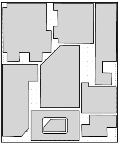
this problem can be easily solved by considering the area between the irregular stock and its MER the shapes already assigned positions. Figure 9 shows a solu-tion to an example of nesting on irregular stock. The solusolu-tion was found at the 93,847th node.
4.4. Berth Allocation
Berth allocation problem is to assign the vessels needing services at specific time at specific locations at quay. Each shape is rectangle (‘time x length’) with ES and LF in time axes, between which the shape must be located. The berth allocation is also needed at shipbuilding for fit processes at quay area. Scheduling out-fitting processes, which require service time of several months, is usually simpler than berth allocation problems at ports. In this example, the lengths of the ves-sels are given and the process time or service time is fixed. ES and LF are defined for each vessel, which means there is a slack for each service time. In this exam-ple, the quay is assumed to have the same water depth and its layout to be straight and continuous.
If the problem does not satisfy the following conditions, no solution exists. The first condition means no single service time crosses the scheduling window, and no vessel is bigger than the length of the quay.
(
)
(
)
(
)
(
)
vessel lengthi i Lengthquay and LS ti start and EF ti end
∀ ≤ ≥ ≤ (3)
where, LSi: Latest start time for vesseli (=LFi – Ti)
EFi: Earliest finish time for vesseli (=ESi + Ti)
Ti: service time for vessel i
[image:10.595.235.512.461.712.2]tstart and tend : start time and end time of scheduling window
The second condition means the sum of the areas of all shapes (time x length) cannot exceed the size of scheduling window x the length of quay.
(
)
quay end start lengthi i Length
i ∗ <T ∗ t −t
∑
(4) The third condition means that at each moment, the sum of the lengths of vessels requiring that moment cannot exceed the length of the quay.{ }
(
length)
Lengthquayk i A i
t ∈
∀
∑
< (5) where, tk: time step k. tstart≤ ≤tk tend.{ }
A ={
j LS| j≤ ≤tk EFj}
: all vessels requiring service at time tk.Before start searching, jobs are sorted by ES in ascending order, by length in descending order, and by LF in ascending order. The rationale behind this is “bookshelf rule”. In shelving the books, people usually place the tallest and thickest books on one side to make more rooms useful on top of the books. In order to expedite searching, it is reasonable to assign jobs with the earlier ES first. The length and LF are used not only to expedite searching but to maximize the chunk of unassigned area in time-length space in order for the space to be useful.
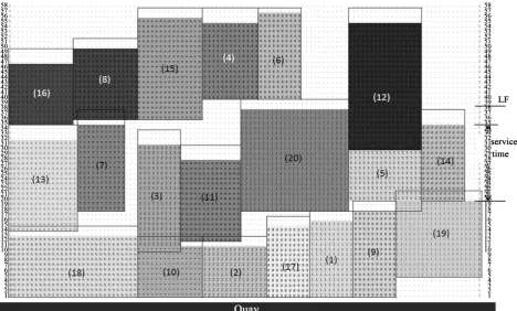
[image:11.595.65.534.427.709.2]Figure 10 shows the result of a berth allocation example, in which horizontal axes shows quay area and vertical axes shows time. In Figure 10, each rectangle shows the length of vessel (width) and service time (height). The solid lines show ES and LF of each vessel. The solution was found at the 1782th node.
Berth allocation problem is an NP-hard problem. The search space, however, for scheduling outfitting jobs in shipyard is of reasonable size. In one of the world’s biggest shipbuilding companies, about ten vessels are in quay area for outfitting at the same time and the duration of each job is several months. In ad-dition to that, the job has upper and lower limits (LF and ES), which further re-duce the search space.
5. Conclusions
This paper presents an expert system based on heuristics to solve various two dimensional nesting problems. The system was developed in CLIPS, an expert system shell, and applied to examples for general nesting, nesting on a blank with irregular boundary, nesting on flat-bar in shipbuilding, and birth allocation for outfitting work in shipbuilding. Each application has different constraints so that the system can use different representation of facts and/or utility functions.
The system used pixel representations for shapes with which nesting on a blank with irregular boundary could be easily solved by regarding the area be-tween MER and the boundary of the blank as the shapes already laid. Pixel re-presentation has many advantages over approximate polygon rere-presentation in that it can be easily prepared from bit-map images that can be obtained from various sources including CAD systems. The system presented can nest a part inside another hollow part, which is difficult with approximate polygon method. For general nesting, the sum of overlapping areas between a part and the parts already laid on the blank is used as a utility function to maximize the utilization of the blank.
The system can also solve the berth allocation problem, which is to nest the rectangular shapes with “service time x the length of the vessel” on a blank with planning window in time × the length of quay. A shape has a float equal to LF - ES-service time. For berth allocation problems, pre-screening and simple heuris-tics are used in searching.
Searching becomes slow as the problem space grows. In order to expedite searching, a utility function is used to sort the nodes in expanding the search tree. For larger problem, however, it may be needed to reduce the resolution of pixels to expedite searching. Considering all the constraints and the number of ships to schedule, on the other hand, the search space for scheduling outfitting jobs in shipyard is of reasonable size.
Expert system is a promising approach for nesting and berth allocation prob-lems since they have discrete number of possible solutions and the performance can be improved by easily adding more rules at implementation stage. This re-search shows that expert system can easily adapt to different kinds of constraints at various application domains.
Acknowledgements
References
[1] Bennell, J.A. and Oliveira, J.F. (2008) The Geometry of Nesting Problems: A
Tutori-al. European Journal of Operational Research, 184, 397-415.
[2] Burke, E.K., Hellier, R.S.R., Kendall, G. and Whitwell, G. (2007) Complete and
Ro-bust No-Fit Polygon Generation for the Irregular Stock Cutting Problem. European
Journal of Operational Research, 179, 27-49.
[3] Babu, A.R. and Babu, N.R. (2001) Ageneric Approach for Nesting of 2-D Parts in
2-D Sheets Using Genetic and Heuristic Algorithms. Computer-Aided Design, 33,
879-891.
[4] Weng, W.-C. and Kuo, H.-C. (2011) Irregular stock Cutting System Based on Auto
CAD. Advances in Engineering Software, 42, 634-643.
[5] Sherif, S.U., Jawahar, N. and Balamurali, M. (2014) Sequential Optimization
Ap-proach for Nesting and Cutting Sequence in Laser Cutting. Journal of
Manufactur-ing Systems, 33, 624-638.
[6] Zheng, J., Jiang, Z., Chen, Q. and Liu, Q. (2011) Spatial Scheduling Algorithm
Mi-nimizing Makespan at Block Assembly Shop in Shipbuilding. International Journal
of Production Research, 49, 2351-2371. https://doi.org/10.1080/00207541003709536
[7] Koh, S., Logendran, R., Choi, D. and Woo, S. (2011) Spatial Scheduling for Shape-
Changing Mega-Blocks in Shipbuilding Company. International Journal of
Produc-tion Research, 49, 7135-7149. https://doi.org/10.1080/00207543.2010.535863
[8] Bierwirth, C. and Meisel, F. (2010) A Survey of Berth Allocation and Quay Crane
Scheduling Problems in Container Terminals. European Journal of Operations
Re-search, 202, 615-627.
[9] Lee, W.-C., Ma, H. and Cheng, B.-W. (2008) A Heuristic for Nesting Problems of
Irregular Shapes. Computer-Aided Design, 40, 625-633.
[10] Tay, F.E.H., Chong, T.Y. and Lee, F.C. (2002) Pattern Nesting on Irregular-Shaped
Stock Using Genetic Algorithms. Engineering Applications of Artificial Intelligence,
15, 551-558.
[11] Lee, C.S. and Park, G.R. (1996) Automatic Nesting and NC Cutting of Flat-Bar. IE
Interfaces, 9, 283-297.
[12] Lee, C.S., Heo, E.-Y., Shim, J.-H., Chen, F.F. and Kim, D.-W. (2013) Ship and
Nest-ing by Pattern Recognition and Group Arrangement. Robotics and Computer-
Integrated Manufacturing, 29, 56-63.
[13] Frojan, P., Correcher, J.F., Alvarez-Valdes, R., Koulouris, G. and Tamarit, J.M.
(2015) The Continuous Berth Allocation Problem in a Container Terminal with
Submit or recommend next manuscript to SCIRP and we will provide best service for you:
Accepting pre-submission inquiries through Email, Facebook, LinkedIn, Twitter, etc. A wide selection of journals (inclusive of 9 subjects, more than 200 journals)
Providing 24-hour high-quality service User-friendly online submission system Fair and swift peer-review system
Efficient typesetting and proofreading procedure
Display of the result of downloads and visits, as well as the number of cited articles Maximum dissemination of your research work
Submit your manuscript at: http://papersubmission.scirp.org/