TRINITY COLLEGE DUBLIN
D
EPARTMENT OFM
ECHANICAL&
M
ANUFACTURINGE
NGINEERING“C
OOLING BY HIGH SPEED AIR JET IN
ORTHOGONAL MACHINING OPERATIONS
”
Thesis submitted to Trinity College Dublin for the degree of doctor of
philosophy by
Andrea Bareggi
May 2010
S
UPERVISORS
:
DR.
G.E.
O’D
ONNELL
Declaration
This thesis has not been submitted as an exercise for a degree at any other university.
Except where otherwise stated, the work described herein has been carried out by the
author alone.
This thesis may be borrowed or copied upon request with the permission of the
librarian, Trinity College, University of Dublin. The copyright belongs to the
Acknowledgements
I would like to take this opportunity to thanks all those have helped me in this project.
First of all I wish to recognise my supervisors, Prof. Andrew A. Torrance and Dr.
Garret O’Donnell, for their valuable support and guidance. Other members of the
teaching and research staff, Dr. Darina Murray, Darko Babic, Dennis DePellegrin and
Tahdg O’Donovan for their advice, and the technical staff, Peter O’Reilly, Gerard
Byrne, Paul Normoyle, J.J.Ryan, Sean Doonan and Michael Reilly for their technical
support and the patience demonstrated in the experimental phase of the project. Finally
I want to thanks my parents, Emilio and Marisa, for their support during all these years
Abstract
Changing environmental awareness has led manufacturing industry to give critical
consideration to the use of conventional coolants and traditional cooling techniques in
machining processes. Current research shows that impinging gas jets have a much
greater potential for reducing the temperature in cutting operations than previously
suspected. In this work the mechanical effect produced by a high speed air jet
impinging on the cutting area at different directions and pressures was critically
investigated. Experimental tests with different pressures and nozzle directions indicate
that the mechanical effect of the air jet contribute significantly to the reduction of
cutting temperature. The tests show better performance in terms of cooling when the air
jet is directed onto the top face of the chip.
The purpose of this work is to provide an explanation for the phenomena observed in
the orthogonal cutting tests on AISI 1020 low carbon steel, assisted by an air jet, where
the mean chip-tool interface temperature was inferred from measurements made by a
thermocouple embedded in the tool.
Finite element simulations show a qualitative relation between the performance of the
air jet in terms of reduction of cutting temperature and the amount of effective stress in
the shear zone, and also within the insert, next to the chip-tool interface. An analytical
model based on energy consideration was developed for explaining the correlation
between the altered state of stress in the shear zone shown in the finite elements model
and the reduction of the temperature in the cutting zone. The deformation energy
induced by the air jet and the thermal energy dissipated by the cooling effect were
introduced in the analytical model. The air jet is considered as an external and
stationary source of energy. The trends of the results from the analytical model show
good agreement with the trends shown by finite element simulations and experimental
Table of Contents
Declaration I
Acknowledgements II
Abstract III
Table of Contents IV
Nomenclature VII
1. Introduction
1.1 Context 1
1.2 Research objectives 5
1.3 Methodology 5
2. Literature review
2.1 Introduction 10
2.2.1 New trends in cleaner production 10
2.2.2 Cutting fluids 12
2.2.3 Minimum quantity cooling and lubrication 16
2.2.4 Alternative cooling methods 21
2.2.5 The mechanical effect of the air jet 24
2.3 Machining assisted by external source of energy 27
2.4 Heat transfer by impinging jet 28
2.5.1 Finite elements modelling in metal cutting 30
2.5.2 Flow stress and friction 31
2.5.3 Finite elements applications in machining 32
2.6 Temperature measurement techniques in orthogonal cutting 34
2.7 Conclusions 36
3. Finite element modelling of orthogonal cutting
3.1 Finite element method overview 37
3.2 The choice of FE software 38
3.3 Geometry and mesh 40
3.5 Incremental 3D thermo-mechanical simulations of orthogonal cutting 46
3.6 Stationary 3D thermal simulations of the insert 49
3.7 2D thermo-mechanical simulations with air jet 54
3.8 2D simulation results 55
3.9 Summary and conclusions 64
4. Analytical modelling of air jet assisted orthogonal cutting
4.1 Introduction 71
4.2 Shear strain and slip line field theory 76
4.3 Shear stress in metal cutting and estimation of cutting forces 81
4.4 The effect of induced chip deformation on the energy balance 85
4.5 Heat transfer to an impinging jet 94
4.6 Overall energy balance 97
4.7 Estimation of the shear plane temperature and interface temperature 98
4.8 Discussion and conclusions 103
5. Experimental investigation
5.1 Experimental procedure overview 107
5.2 Temperature measurement: the embedded thermocouple 113
5.3 Data acquisition and test procedure 116
5.4 Summary of the experimental setup 120
5.5 Experimental tests results 121
5.6 Summary and conclusions 129
6. Results and discussion
6.1 Introduction 130
6.2 Chip formation and morphology 131
6.3 Discussion on experimental test – embedded thermocouple 139
6.4 Comparison of results: analytical model, finite element model and
experimental tests 140
6.5 Summary and conclusions 146
7. Conclusions and further works
7.2 Materials and methods 148
7.3 Results 151
7.4 Further research 153
References 155
Nomenclature
Symbol Description Units
A chip-tool interface shape coefficient [-]
B friction slider coefficient [-]
b depth of cut [mm]
C friction slider coefficient [-]
c specific heat [J/kg K]
diam diameter of the nozzle [mm]
dist distance between nozzle exit and chip surface [mm]
e eccentricity (chip) [-]
f frequency [Hz]
Fp force normal to rake face [N]
Fq force tangential to rake face [N]
Fs shear force (tangential to shear plane) [N]
Fc friction force (tangential to rake face) [N]
h convective heat transfer coefficient [W/m² K]
k thermal conductivity (generic) [W/m K]
L length of the heat generation zone [mm]
Lcontact length of chip-tool contact [mm]
Lstick length of chip sticking contact [mm]
Mover, int moment promoted by the air jet [Nm]
Ma Mach number [-]
n strain hardening coefficient [-]
Nc normal force between tool and chip [N]
Ns normal force on the shear plane [N]
Nu Nusselt number [-]
p pressure of the air jet [Pa]
Pr Prandtl number [-]
rt thickness ratio [-]
ro external radius of the chip [mm]
ri internal radius of the chip [mm]
Rc chip curvature radius [mm]
R total cutting force [N]
R1,2,3 heat partition coefficient [-]
Re Reynolds number [-]
St Strouhal number [-]
t feed rate [mm/rev]
t1 chip thickness [mm]
T temperature (generic) [K]
Ts temperature of the shear plane [K]
Tt chip-tool interface temperature [K]
Tmod modified temperature (Oxley) [K]
u specific cutting energy (generic) [MJ/m³]
us specific cutting energy by shear [MJ/m³]
uf specific cutting energy by friction [MJ/m³]
uH energy associated to heat transfer [MJ/m³]
uM energy associated to elastic deformation [MJ/m³]
V cutting speed [m/s]
Vflow air jet speed [m/s]
Greek symbols
α shear plane angle [deg]
β friction angle [deg]
γ shear strain [-]
γ& shear strain rate [1/s]
θ correction for shear plane angle [deg]
ϑ angular coordinate (chip) [rad]
Φ shear plane angle [deg]
ε strain (generic) [-]
µ friction coefficient [-]
ρ density (generic) [kg/m³]
σ stress (generic) [MPa]
σel elastic stress [MPa]
σ1 stress with unitary strain [MPa]
τ shear stress [MPa]
1. Introduction
1.1 Context
Since the beginning of the 20th century manufacturing processes have been systematically
and scientifically developed and analyzed in order to maximize the efficiency of the
processes and to generate a new knowledge and understanding of processes. Byrne et al
[1, 2] identified the change drivers in the development in manufacturing process
innovation, including: diminishing component size, enhanced surface quality, tighter
tolerances and manufacturing accuracies, reduced costs, diminished component weight
and reduced batch sizes. These change drivers have a direct influence on the primary
inputs to the cutting process namely the cutting tool and tool material, the workpiece
[image:11.612.141.475.368.624.2]material and the cutting fluid.
Figure 1.1 – The roadmap for advancing cutting technology [1]
In the past decades within the industrial community there is increasing awareness, that
manufacturing processes [14]. The challenges associated with environmental protection
and energy efficiency in relation to manufacturing is now an area of ongoing and vibrant
research activity, as outlined by Byrne et al. [1], Klocke et al. [3] and Weinert [4].
More recently the increasing sensitivity to environmental and health issues is reflected in
the increasingly stringent legislation. The restrictions resulting from legislation do not
only lead to limitations and difficulties with particular manufacturing processes and an
associated undesirable cost factor, but also force scientists and engineers to develop new
and alternative technologies. This provides a technological challenge and increases the
importance of ecological manufacturing as a competitive factor. This has been the source
of a number of initiatives to encourage more research in environmentally efficient
manufacturing processes. Klocke et al. [5] reports environmentally efficient machining as
one of the main issues stimulating the foundation of the CIRP Working Group on High
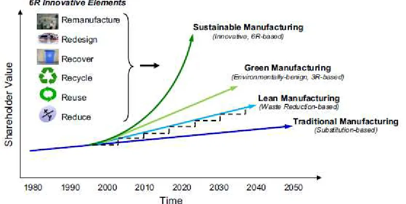
Performance Cutting. According to Pusavec et al. [6] in the US an initiative on
environmentally benign manufacturing has been ongoing since early ‘90s. This initiative
is mostly based on innovative sustainable manufacturing, as shown in Figure 1.2.
Figure 1.2 – Efficient sustainable machining is based on remanufacturing, redesigning,
recovering, recycling, reusing and reducing [6]
When considering the environmental efficiency of a machining processes one of the main
[image:12.612.96.515.385.596.2]workpiece [7]. Temperatures at the chip-tool interface play a major role in tool wear and
can also result in modification to the properties of the workpiece and tool materials [8].
As there is a general move towards environmental efficient machining, it is increasingly
important to understand how machining temperatures are affected by the process
variables involved and by other factor such as tool wear [140, 121]. According to Klocke
et al. [5] the increase in power to remove more material in a shorter time increases the
heat generation near the cutting edge of the tool. The power consumed in metal cutting is
largely converted into heat, for example in the case of low carbon steels approximately
80% of the power input is converted into heat. This heat is dissipated by the five systems
processing the material: the cutting tool, the workpiece, the chip formed, the cutting fluid,
and the natural convection to air. This means that the cutting tool needs to support higher
temperatures at acceptable wear rates [11]. Normally, the temperature achieved by the
cutting tool is the factor that limits the rate of machining. This task forced the
development of new materials for cutting tools that can resist high temperatures, and
methods for managing the temperature rise at the chip-tool interface. The approaches
used to manage temperature at the tool chip interface can be broadly classified as
management of the temperature by heat transfer (use of cutting fluids, minimum quantity
lubrication, and alternative cooling methods) or management of temperature by
manipulation of frictional contact [12].
According to Bacci da Silva et al. [58] cooling and lubricating is also a subject of much
research activity and it is generally accepted that oil-based cooling/lubrication fluids are
one of the most unsustainable elements of machining processes. Cutting fluids have a
direct influence on the environment and since early ‘90s are being questioned in the light
of economic and ecological manufacture [6]. The exposure of the production operator to
cutting fluids can lead to skin and respiratory diseases and there is increased danger of
cancer. The cause of this is attributable both to the constituents of the cutting fluids as
well as to the reaction products and particles generated during the process [1].
Studies on minimum quantity lubrication and oil mists are relatively well established, as
reported by Weinert [4]. However Childs et al [13] reports that the lubricant can gain
only a partial access to the chip-tool interface, and so attention should be focused on the
penetrates only the sliding zone, which makes only a small contribution to the total
forces, it will only marginally affect the total force. The sliding zone has the lowest
compressive forces and as such can be influenced by small changes in the cutting
process. Current strategies for reducing the cutting temperature include the use of
multi-layer coatings [14] and self-lubricating coatings in dry machining, and alternative cooling
methods (cryogenic technology and manipulation of the frictional contact in the chip-tool
interface.
Well established studies on dry cutting, reviewed by Klocke et al. [3], and a strategic
approach to high performance cutting in the environmental efficient direction [5] suggest
that most of materials (with the exclusion of titanium alloys and nickel based alloys) can
be dry machined with multi-layer coatings and self-lubricating coatings (soft coatings)
[15]. More recently, cooling systems based on cryogenic technology [16, 17] provided a
sustainable alternative to the use of cutting fluids, traditional (flooding) or improved
(minimum quantity lubrication or oil mist) [18].
One alternative process for the management of temperature at the tool-chip interface
consists of manipulating the frictional contact in the chip-tool interface. According to
Friedman and Lenz [19] there is a correlation between maximum interface temperature
and chip morphology (curl of the chip and length of the sticking zone). Umbrello et al.
[20] estimates the global heat transfer between the chip and the insert as dependent on the
stress and temperature in the sticking zone. Studies carried out by Ozel and Altan [21]
show that the friction and hence the temperature rise due to friction can be reduced by
reducing the stress in the sticking region. The manipulation of the frictional contact can
be achieved by using an external source of energy for promoting a deformation in the
chip. One of the main purpose of laser and plasma based techniques is the local
modification of material properties (such as hardness and stiffness) just before the shear
zone, in order to reduce the specific cutting energy required for cutting, hence the stress
on the rake face [49, 5, 25].
The approach proposed in this research is based on using high velocity air jets to assist
the orthogonal cutting process. The air jet impinging on the surface of the workpiece in
the contact zone, on the tool and on the chip introduces both thermal and mechanical
1.2 Research objectives
The aim of this research is to investigate the use of a high velocity air jets to assist the
orthogonal cutting process, both from a thermal and mechanical point of view. A
particular focus of this work was the mechanical effect of the air jet impinging on the
cutting zone.
• The research set out to develop an analytical model of the orthogonal cutting process assisted by high speed impinging air jet considering the mechanical and
thermal effect.
• The research set out to develop a finite element model of the orthogonal cutting process assisted by high speed impinging air jet in order to investigate the effect
of the mechanical and thermal effect of the air jet on cutting temperatures
including shear plane temperature, and temperature distribution within the insert,
effective stress within the insert and the workpiece, and chip morphology
including curvature radius, chip thickness, length of the contact with the rake
face.
• The research work concluded with experimental investigations in order to validate
the analytical and finite element models, and provide a sensitivity analysis to the
variation of pressure and position of the nozzle.
1.3 Methodology
Background
The mechanical effect of the high velocity air jet is considered as a pressure applied to
the top face of the chip or into the interface between the bottom face of the chip and the
tool. The pressure applied by the high velocity air jet promotes the elastic deformation of
the chip. This deformation promotes a rotation of the chip that tends to reduce the
curvature of the chip. In this work, a hypothesis is presented that the alteration of the
radius of curvature) or with a decrement of energy (increased radius of curvature), as
suggested by Baker [10].
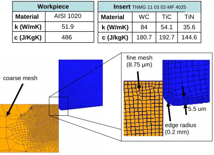
In order to develop the argument, the orthogonal cutting process was chosen as the basis
for the investigations. The workpiece material was a low carbon steel AISI 1020 and
coated tungsten carbide tools TNMG 110302-MF4025 were used. The orthogonal cutting
process is well established and well published with significant information available on
analytical, finite elements and experimental investigations. Furthermore by primarily
considering 2D investigations it was also possible introduce the additional element of the
high velocity air jet into the cutting process and to critically consider the sensitivity of the
high velocity air jet nozzle position.
Approach
The research project is based on three pillars:
• The development of an analytical model of 2D orthogonal cutting with the
integration of the mechanics of the high velocity air jet
• The development of a finite element of 2D orthogonal cutting with the integration
of the mechanics of the high velocity air jet. The development of 3D models of
the temperature distribution in the cutting tool with the mechanics of high velocity
air jet included.
• Experimental investigations with high velocity air jet impinging on the cutting zone under two different impinging conditions
The three pillars of the methodology are graphically illustrated in the Figure below
Figure 1.3 – The schematic plan of the research project
Analytical model development
An analytical estimation of the shear plane angle, the strain and the strain rate was coded
in MATLAB by using the approach of Merchant [28, 29] and Kececioglu [30]. The shear
plane angle, the strain and the strain rate were used to calculate the flow stress as a
function of temperature in the workpiece material using the model proposed by Oxley et
al [31, 32, 33]. The flow stress was used in the orthogonal cutting model by Merchant
[29]. The cutting forces calculated by using the orthogonal cutting model were used for
estimating the specific cutting energy in its components Us (in the shear zone), and Uf (in
the friction zone).
The mechanical effect of the air jet on the chip was modeled as a distributed load on a
curved elastic beam, and the solution of Saint Venant was used for estimating the
deformation energy (Um) associated with the elastic deformation [34]. The heat transfer
by impinging jet was modeled by estimating the Nusselt number for circular jets
Analytical estimation of: -shear plane angle -strain
-strain rate
2D FEM of orthogonal cutting with thermal and mechanical effect of the air jet
3D FEM of embedded
thermocouple Calibration of the embedded thermocouple Orthogonal cutting
model (Shaw and Jaeger)
Orthogonal cutting tests Flow stress model
by Oxley Conclusions Verify models Validate model Experimental tests Finite elements Analytical model
2D FEM of orthogonal cutting
Contribution of the mechanical effect by air jet to the
specific cutting energy Complete model MATLAB CODED MATLAB CODED
3D FEM of orthogonal cutting
DEVELOPED AND CODED DEVELOPED AND CODED
impinging on round surfaces, and the heat flux Uh was considered in the energy balance.
The two contributions (Um and Uh) to the energy balance were evaluated for two nozzle
positions: the nozzle directed on the top face of the chip known as the overhead position
and in the chip-tool interface known as the interface position.
The components of the specific energy were the inputs of the model developed by Shaw
[35, 39], that calculates the temperature in the shear zone, and by Jaeger [38], that
calculates the temperature rise in the friction zone according to the flash temperature
theory [40] and the maximum insert temperature.
Finite element modeling
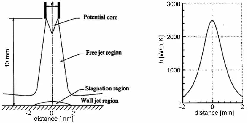
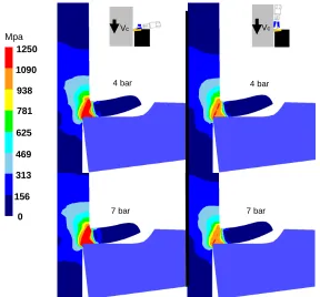
2D simulations of orthogonal cutting were modeled using DEFORM-2D. The 2D
simulations boundary conditions included the heat transfer by impinging jet, modeled as
forced convection by using a heat transfer coefficient (h = 2000 W/m²K), and the
mechanical effect of the air jet on the chip, modeled as a pressure applied on the
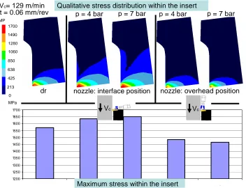
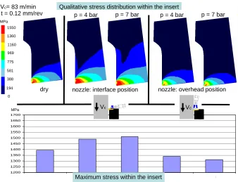
impinged surface. The 2D simulation results include the temperature distribution within
the insert and the workpiece, the effective stress distribution within the insert and the
workpiece, the 2D chip morphology. The temperature and stress distribution within the
insert were particularly influenced by the variations to the direction and pressure of the
air jet. The influence of the direction and pressure of the jet was observed also by Diniz et
al. [41] in low carbon steel turning tests.
3D simulations of orthogonal cutting without the use of air jet were modeled using
DEFORM-3D. The purpose of the 3D simulations was the investigation of 3D
morphology of the chip, in particular the contact between the chip and the insert. The 3D
morphology of the chip was used as a boundary condition for the 3D thermal simulations
on the insert with embedded thermocouple. The 3D thermal simulations of the insert were
used for modeling the temperature in the insert with the embedded thermocouple. The
thermal simulations of the temperature within the insert provided a relation between the
maximum temperature of the chip-tool interface and the temperature read by the
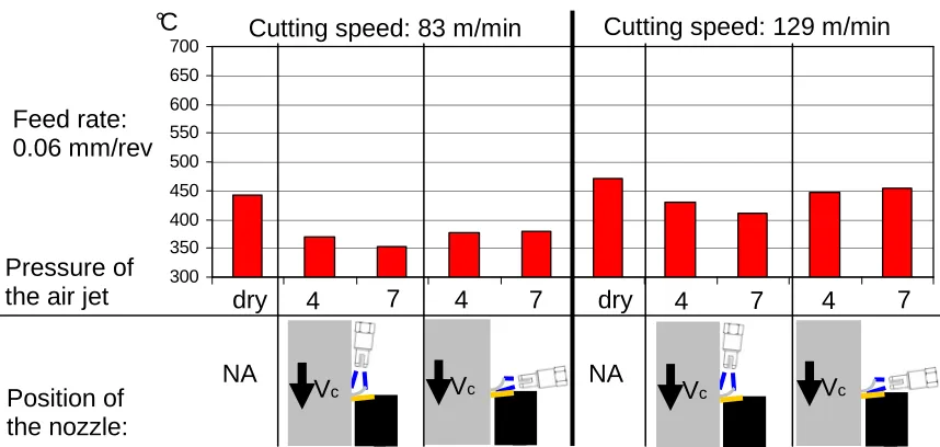
Experimental tests
Experimental investigations were carried on AISI 1020 low carbon steel by using a
coated insert TNMG 110302-MF4025. A nozzle holder with three degrees of freedom
was designed and manufactured. A data acquisition system was commissioned that
recorded forces from a three component cutting force dynamometer. The tool temperature
was measured by embedding a thermocouple into a cutting tool insert. The tool was
calibrated in order to account for the heat transfer through the insert from the cutting tool
face. The high velocity jet was directed in four directions, two on the top face of the chip
in the overhead position and two in the interface between the chip and the rake face in the
interface position in order to provide a sensitivity analysis on the positioning of the
nozzle. The main set of tests used two pressures of the air jet (4 and 7 bar), and a set of
tests was carried out with small variation of pressure in order to evaluate the sensitivity to
the pressure of the air jet. In order to ensure the reliability of the temperature
measurement with embedded thermocouple, all the main set of tests was carried out by
using two holes for embedding the thermocouple. The results from the orthogonal cutting
2. Literature review
2.1 Introduction
Metal cutting is one of the most important methods of removing material in the
production of mechanical components. The industrial production of useful parts and
objects by the removal of material, for the purpose of producing a desired shape, is today
almost exclusively carried out by the processes known as machining and grinding [43]. In
machining the metal is removed by sharp-edged cutting tools propelled and guided by
precise machines termed machine tools. Thus, the technology of the machining is
primarily concerned with the characteristics and performance of three main players;
namely, the cutting tool, the machine tool and the material being cut [139].
A review of CIRP activities since its foundation [44] shows that metal cutting represents
a strong integration of technologies and management using information technologies,
integration of the process planning and production planning, simulation of manufacturing
systems, agile manufacturing, fast redesign of new products, modeling of manufacturing
equipment performance, including the human operator, functional product analysis,
virtual machining and inspection algorithms.
The literature review presents the currently used solutions for reducing cutting
temperature in machining operations, with particular emphasis on clean production and
air jet based cooling technology. Also a literature review on particular finite element
applications is presented, since finite element investigations is one of the three pillars on
which this research is carried out. A review on the different temperature measurement
methods is also presented.
2.2.1 New trends in cleaner production
The global environmental problems caused by the consumption of natural resources and
pressure and stronger regulations being applied to both the manufacturers and users of
such products [14]. The idea of sustainable development is well defined and implemented
on the production at a macro level, but there is a severe lack of implementation practices
on the shop floor dealing with machining technologies [1]. Industry is striving to achieve
sustainability through changes in product, material cycles, the recovery of resources, and
innovations in production practices in order to fulfill the objectives of sustainable
development [45, 46]. With the implementation of sustainability principles in machining
technologies, end-users have the potential to save money and improve their
environmental performance even if their production stays in the same range or decreases
[47]. According to Pusavec et al. [6] in the view of production technologies, the ways to
improve the sustainability performance are to:
• reduce machining processes energy consumption
• minimize waste (generate less waste, and increase waste recycling)
• use resources efficiently
• use recyclable materials or reuse machine-tool components
• improve the management of metalworking fluids
• adopt life cycle assessment methods
A key element of sustainability is the prudent use of natural resources. This means using
non-renewable resources efficiently and developing alternatives to replace them in the
future, while using renewable resources in ways that do not endanger the resource or
cause pollution [48]. The main resources of concern in production technologies are:
metals used in the machining processes, cooling/lubrication fluids/oils and hydraulic oils,
water, and energy. In particular the increasing cost pressure on industrial enterprises has
led to a critical consideration of conventional coolants used in most machining processes.
Depending on the workpiece, the production structure, and the production location the
costs related to the use of coolants range from 7 - 17% of the total costs of the
manufactured work piece [3]. By abandoning conventional coolants and using the
technologies of dry machining, this cost component can be reduced significantly (Figure
Figure 2.2 – production costs related to a machining process [3]: the cooling lubricant
represents the 7-17% of the total production costs
Besides an improvement in the efficiency of the production process, such a technology
change makes a contribution to the protection of labour and the environment. The
reduction of substantial exposure to coolants in the work place raises job satisfaction and
improves the work result at the same time. Furthermore, an enterprise can use
economically friendly production processes for advertising purposes, which leads to a
better image in the market [4].
2.2.2 Cutting fluids
Early experiences in metal cutting demonstrated the ability of mineral oil in cooling the
cutting area, and this has led to the development of fluids specifically designed for metal
cutting [18]. The primary functions of cutting fluids are cooling and lubrication. Early
observations in metal cutting [50] show that a fluid's cooling and lubrication properties
are critical in decreasing tool wear and extending tool life. Cooling and lubrication are
also important in achieving the desired size, finish and shape of the workpiece. A
secondary function of cutting fluid is to flush away chips from the tool/workpiece.
Cooling techniques influences the machining process in various ways. At the contact
between the chip and tool, cooling can reduce the chip temperature and, thus, affect
so high that the cutting fluid has no access to the contact area [52]. The cutting fluid
always plays a major role in maintaining the machined material at low temperature, and
the demands of high performance cutting require improved cooling ability [53]. Low
temperatures were correlated with smaller cutting forces and small chip curl diameters;
higher temperatures were associated with high cutting forces, and larger chip curl
diameters [54]. According to Sales et al. [56] cutting oils as well as aqueous coolants
reduced cutting temperature, the former indirectly by reducing heat generation through
improved lubrication, the latter by heat removal. Lubricants reduce friction between
surfaces which are in relative motion. At any given rate, the force pressing the parts
together controls the intimacy of contact and thus has a direct influence on frictional
force. From a tribological point of view, the reduction of the friction between two moving
parts depends on the thickness of the layer of fluid, and the thickness depends on the
viscosity of the fluid [56]. According to De Chiffre [57], when normal forces are quite
low, the viscosity of an intervening layer of fluid can be the major factor in regulating
friction. Sales et al. [56] report other properties of the cutting fluid: concentration, fungi
and bacteria control, emulsion stability, and pH. However, the most important property
considered for this research project is heat transfer ability, and the comparison of the heat
transfer coefficient of different cutting fluids and high speed impinging air jet. The most
common metalworking fluids used today belong to one of four following categories:
• oil based fluids including straight oils and soluble oils
• chemical fluids including synthetics and semi synthetics
• biological fluids
• foams
According to Hoff [53], the first two categories include fluid that may be hazardous for
the operator’s health: skin irritation caused by the cutting fluid is well known since early
steps of machining technology. However, new trends in using foams and mists lead to
critically consider the impact of these new cooling and lubricating techniques on the
health of the operator as potential cause of respiratory disease and skin and pulmonary
essential for the design and accurate selection of a cutting tool for a specific machining
application. The maximum temperature generated during machining usually dwells not
exactly at the cutting edge, where the compressive and shear stresses are at their highest,
but further away on the rake face as shown Davies et al. [60] and Abukhshim et al.[61].
In order to rank cutting fluids according to their cooling ability, cutting temperatures are
usually determined experimentally and used as the criterion for comparison. Cutting
fluids are also important for lubrication, but in practical conditions it is very difficult to
achieve good penetration into the tool-chip interface [13]. Sales categorized the
characteristic of various cutting fluids considering their properties and applications. Six
different cutting fluids were used:
• Water: Very good cooling quality and poor lubrication quality
• Integral neat oil: Good lubrication and anti-corrosion properties but low specific heat
• Soluble oil has high specific heat with good heat dissipation capability. They possess in their formulation sodium based additives that can reduce superficial
stress of the vapour bubbles that occasionally form at elevated temperatures,
hindering heat exchange
• Synthetic fluids 1&2 have high specific heat with excellent heat conduction characteristics. Synthetic fluids are polyglycol based, containing water and
additives in their formulation. The Synthetic 1 fluid has higher quantities of
additives in comparison to the Synthetic 2, therefore it also have a higher
viscosity, compared to the Synthetic 2
Sales et al. [56] carried out a series of investigations using AISI 8640 steel and a K10
cemented carbide which quantified the performance of the cutting fluids as shown in
Figure 2.1 – effects of different cutting fluids on cutting temperature (Sales et al.) [56]
The chip-tool interface temperatures encountered in an increasing order are: integral neat
oil, dry, emulsion, synthetic fluid 2, water and synthetic fluid 1. The chip-tool interface
temperatures were measured using a infrared thermometer. De Chiffre [57] evaluated the
performance of integral neat oil, soluble oil and synthetic fluid with sulphur and chlorine
additives using the torque of the tool during drilling operations as the controlling
parameter to classify the fluids. In two variants of these tests he used pre-drilled holes
and tapered holes and concluded that the test is very sensible to the cutting process, the
cutting conditions as well as to the established performance criteria. However both De
Chiffre and Sales remark that a high heat transfer coefficient of the fluid is not
necessarily beneficial, since the cooling ability of the fluid, by reducing the temperature
in the shear zone also reduces the softening effect due to the temperature rise in the shear
area, consequently increasing the hardness of the workpiece material and causing a local
temperature rise. This effect was observed also in the investigation of Liu [62] about the
influence of the workpiece hardness on changes in cutting temperature and tool wear.
According to Seah et al. [63] the overall effect of applying flood coolant in machining is
not always beneficial in terms of wear, since the softening effect that is present with the
cooling. In the experiments carried out by Seah the low and medium carbon steels AISI
1045 and AISI 4340 were machined on a lathe at a cutting speed of 130 and 190 m/min at
a feed rate of 0.15 and 0.20 mm/rev, and a water based coolant was used on the cutting
area at a flow rate of 2.5-3.0 l/min (flooding). The findings of Seah are compared with
the observation of Shaw [67] on machining of AISI 1020 and AISI 4340. Shaw also
report that the use of coolant resulted in a significant shift of the centre of the crater
towards the cutting tool tip. Experiments from Seah are consistent with the observations
of Shaw. Investigations carried out by Al Huda [64] using a two colour pyrometer for
measuring the temperature at the chip-tool interface during AISI 1045 machining at
different cutting speeds and feed rates show a minimal reduction of the temperature (less
than 3%) when using flood coolants, compared to dry cutting.
2.2.3 Minimum quantity cooling and lubrication
Within the context of dry machining, the term MQCL is generally used to refer to the
supply of the coolants in the form of an aerosol. Depending on the type and on the main
function of the fluid medium supplied, a distinction can be drawn between minimum
quantity lubrication (MQL) and minimum quantity cooling (MQC), according to Figure
2.3. Extensive MQL research has been carried out, including comparison with dry cutting
conditions [68, 69, 70, 71, 72]. In contrast to minimum quantity lubrication (MQL),
minimum quantity cooling (MQC) has, until now, been a seldom used, and therefore
largely unexplored, component of the MQCL technique among industrial users.
However, the minimum quantity cooling technique can make a major contribution to the
solution of thermal problems affecting the tool and/or the part in dry machining
operations [4]. These techniques include high-pressure air jets, water vapour [74] and
Figure 2.3 – classification of MQC and MQL lubrication and cooling techniques [4]
Diniz et al. [68] has carried out comparative experiments using a CBN tool cutting a
hardened steel AISI 52100 workpiece (45–65 HRC) on a lathe, with different cooling
methods. Part of the experimental apparatus was a mist coolant device which precisely
regulates the oil flow at a constant pressure of 4.5 bar. The nozzle was positioned, 10
mm. away from the tip of the tool, as shown in Figure 2.4. Two phases of experimental
investigations were carried out: preliminary experiments and tool life experiments.
[image:27.612.223.352.566.679.2]The preliminary experiments were carried out aiming to establish the best oil flow in the
flow of air. The following conditions were used:
• dry cutting;
• compressed air (without any liquid);
• overhead flood (wet cutting with oil/water=1/20);
• MQL with 10 ml/h;
• MQL with 30 ml/h;
• MQL with 60 ml/h.
The cutting conditions used in these experiments were:
cutting speed V =110 m/min; feed rate t =0.08 mm/rev.; depth of cut b =0.3 mm. Tool
maximum flank wear and workpiece surface roughness were measured after 553 m of
cutting length had elapsed. Each experiment was made with a fresh edge of the insert.
Diniz reports that the dry condition and compressed air only presented the smallest flank
wear and roughness. This is due to the effect of the high temperature of the cutting zone
and to the high hot hardness of CBN. This result confirms the conclusions of Sales et al.
[56] about the negative effect on cutting performance of coolants with high heat transfer
ability. On the other hand, the softening effect of the workpiece in the shear zone is
difficult to control according to Shaw [67]. The reduced heat transfer ability of
compressed air allows the control of shear zone temperature without hardening of the
workpiece material. For the machining of hardened steel the dry condition seems to be
the efficient [75], however dry cutting of soft steels or aluminium alloys produces
unacceptable friction. Considering the results obtained in the preliminary experiments by
Diniz [68] it can be concluded that the three MQL conditions presented similar results
regarding both surface roughness and tool wear. In terms of cutting speed, the maximum
value (175 m/min) presented the best surface finishing but rapid flank wear and greater
crater wear. The other cutting speeds used did not significantly influence surface
roughness and flank wear.
Rahman et al. [70] used energy dispersive x-ray (EDX) and scanning electron
In particular that authors focuses on investigating the thermal shock in the cutting are due
rapid quenching of the workpiece. Analyses of the cutting force, surface roughness, chip
shape and EDX findings reveal that MQL may be considered as an economical and
environmentally compatible lubrication technique for conventional machining. Their
results with 8.5 ml/h show a considerable reduction in cutting force for the MQL
condition when compared to dry cutting and flood cooling. MQL presented the lowest
cutting force and lowest flank wear at low speed and low feed. MQL showed an
improved tool life compared to flood cooling (insert fracture) and to dry cutting
(consistent flank wear due to high friction). SEM images of chips showed evidence of
major thermal stress in flood cooling and EDX analysis revealed a better lubricating
effect and lower cooling effect for MQL, compared to flooding. Considering the results
of Diniz et al. [68] and Rahman et al. [70], it is possible to conclude that MQL is a
suitable option for traditional cutting, but it is not always for high performance cutting,
and the efficiency of the MQL technique is case specific. Varadarajan et al. [72] and
Vikram Kumar et al. [73] made a comparative study on cooling techniques in hard
turning, considering dry cutting, flooding and MQL with an extremely low rate of fluid (2
ml/min) with high pressure jet (20 MPa). The performance during minimal cutting fluid
application is found to be superior to that during dry turning and conventional wet turning
on the basis of cutting force, tool life, surface finish, cutting ratio, cutting temperature
and tool–chip contact length. As the minimal rate of application is as low as 2 ml/min a
major portion of the fluid is evaporated. These encouraging results could be mostly due
by the high pressure applied on the chip, rather than the effective cooling effect of the
fluid. This is supported by the work of Çakir et al. [76] who established that the jet
pressure in MQL and gas application in machining plays a fundamental role in cooling
the cutting area.
The literature presented on MQCL techniques focus on the consequences of the
conceptual difference between flood cooling and small flow rate cooling. The MQCL
technique avoids the thermal shock that occurs when flood cooling is used, as reported by
Rahman [70]. Also the experiences of Diniz [68] suggest that the compressed air has a
[53] MQL techniques and oil mists successfully match with high performance cutting
operation due to their multiple mechanisms of cooling: the heat transfer due to the contact
of the heated surface with the liquid particle and the change of phase of the liquid particle
(vaporisation). The multiplicity of mechanism lead to a evenly distributed heat transfer
that differs from the use of flood coolants (quenching), and easily leads to thermal shock
[5]. Despite the extensive experimental research on MQL, few efforts were made to
analytically understand the phenomena. Li and Liang [39] modelled the temperature
distributions in the cutting zone under through-the-tool MQL technique, where the
coolant was delivered by a hole in the insert. The temperature rise in the chip, the effects
of the primary heat source and the secondary heat source were modelled as moving heat
sources. For the temperature rise in the tool, the effects of the secondary heat source, the
heat loss due to cooling, and the rubbing heat source due to the tool flank wear, were
modelled as stationary heat sources. For the temperature rise in the workpiece, the
primary heat source, the heat loss due to cooling, and the rubbing heat source due to the
tool flank wear were modelled as moving heat sources. The principle used for developing
this model is similar to the model proposed by Shaw and co workers [67, 35, 36], also
using the Jaeger equations [38] for modelling moving sources of heat and the
temperatures of sliding contacts [40]. The model describes the dual effects of air-oil
mixture in near dry machining in terms of the reduction of cutting temperature through
the cooling effect, as well as the reduction of heat generation through the lubricating
effect. Model calibration and validation was achieved by undertaking experimental
investigation using an embedded thermocouple in an uncoated tool during the machining
of a medium carbon steel. Results show that the tool flank wear has a larger effect on
cutting temperature for high cutting speed.
According to Weinert [4] the optimisation of MQL technique leads to further reduction of
the amount of coolant in the cutting area, often referred as near dry machining. However,
near dry machining conceptually differs from MQL technique since the cooling is
completely achieved by the vaporization of the fluid particles. Also Klocke [5] affirms
the conceptual difference between MQL, near dry machining and dry cutting.
Techniques based on dry cutting implicate important advantages from a technological
minimized and therefore the tool life is increased. Moreover the part quality is improved
since the rim zone of the machined component cannot be hardened by the rapid
quenching due to coolant. However, dry cutting does not represent an improvement in
machining materials with a low thermal conductivity, such as titanium alloys and Byrne
[1] reports that the introduction of dry cutting requires suitable measures to compensate
for the primary functions of the fluid.
2.2.4 Alternative cooling methods
Avoiding the use of cutting fluids in machining operations is one goal of the research in
sustainable machining, due to ecological and human health problems caused by the
cutting fluid. Usually, cutting fluids still provide a longer tool life for traditional
machining operations, but according to Diniz and Micaroni [77] increasing cutting speed
and feed rate reduce the difference between wet and dry cutting. Since dry cutting not
always represent an optimization of the cutting process (typically with difficult to cut
materials), different cooling methods has been experimented, as an alternative to MQL.
Han et al. [74] have investigated the use of water vapour.
The tests were carried out by cutting a workpiece of steel 45 with a hard alloy YT15 tool
at 86.5 m/min, with a feed of 0.15 mm/rev at four different depth of cut (from 0.5 to 3.5
mm), using the following cooling/lubricant method: dry cutting, compressed air, oil water
emulsion, water vapour. Through analysis of the experimental results, water vapour as
coolant and lubricant have better lubricating action because of the good penetration
performance and the low lubrication layer shearing strength of water vapour.
Unfortunately, the use of water accelerates the process of corrosion on the mechanical
parts.
Rahman et al. [75] carried out experiments in order to determine the effective zones of
the cutting conditions for chilled air in comparison with dry cutting and conventional
flood coolant. Chilled air at -30°C at a volume flow rate of 0.4 m³/min at a pressure of 5
bar was used for cooling the cutting area on a milling machine. Tool damage and chip
colour and shape have been observed with SEM and optical photography. Based on the
in chilled air is lower than that for flood coolant at low feed rates and low cutting speeds.
However, the tool wear obtained for chilled air is lower than that for conventional flood
coolant at low depths of cut except beyond a depth of cut in the 0.2 mm region. This
implies that at a lower feed rate, the lubrication ability of conventional flood coolant
decreases because of its large oil droplets, which are unable to penetrate effectively into
the cutting region. At lower feed rates, the effect of the cooling ability of the chilled air is
more evident, thus leading to a lower rate of flank wear. The average surface roughness
of the workpiece is lower for chilled air only at higher feed rates. At higher cutting
speeds, the average surface roughness of the workpiece in chilled air is comparable to
that for flood coolant. The average surface roughness of the workpiece in chilled air is
found to be lower than that for conventional flood coolant at a higher depth of cut.
However, in the case of machining with chilled air, the chilled air was able to cool the
region more effectively than the flood coolant, thus, resulting in a lower average surface
roughness of the workpiece. No significant difference in cutting force was observed
between the use of flood coolant and chilled air, but the cutting force experienced in dry
cutting is higher than that for flood coolant and chilled air because there is little or no
lubrication action present and inadequate cooling. A distinct colour difference, due to
different degrees of oxidation on the surface of the chips, indicated that the cutting region
was cooled more, by a significant amount, in the case of machining with chilled air than
with traditional cooling. Despite the low temperature of the air, Rahman remarks that the
SEM analysis of the chips do not show any thermal shock due to the temperature
difference. The explanation of this behaviour can be addressed to the difference between
the chilled air and a flood coolant in terms of convective heat transfer coefficient. Similar
observations have been made by Paul et al. [17], using a liquid nitrogen jet and
comparing results over dry and wet machining AISI 1060 steel on a lathe.
Specific studies about the effects of the direction of impinging jets, in particular
inclination and distance within the hot surface have been carried out by Stevens and
Webb [78], Elison and Webb [79] and O’Donovan [80]. However these studies are not
related on machining issues. On the other hand an interesting study of heat transfer in
machining was carried out by Li [81], paying particular attention to the direction of the
temperature distribution in the cutting region of machining is investigated through
numerical simulation using the cooling heat-transfer models previously developed. Two
nozzles were placed, one in overhead position, the other along the tool flank, as shown in
Figure 2.5. The AISI 1020 was machined at a relatively low speed (61/m/min) but at high
feed rate (0.2642 mm/rev) and high width of cut (1.88 mm). The coolant was injected by
a nozzle (diameter = 10 mm, distance to shear zone = 40 mm, impingement angle = 60°).
Cutting processes with a water coolant applied in overhead-jet cooling and flank-jet
cooling at different jet-flow rates were investigated. The flow rates considered in the tests
were 10, 15 and 48 l/min for overhead-jet cooling, and 10 and 90 l/min for flank-jet
cooling, respectively.
Figure 2.5 – sketch overhead and flank jet positioning in research carried out by Li [81]
In cutting at the testing conditions with overhead jet cooling, when the jet-flow rate was
increased by 400%, the temperatures along the tool rake face exposed to coolant and
along the flank face were reduced by more than 40% and 26%, respectively, but the
temperatures at the tool cutting edge and along the tool-chip interface, including the
maximum temperature in the overall cutting region, were little changed. The results show
that with the nozzle overhead position it is possible to achieve a good reduction on the
temperature of gas jet, rather than jet speed and pressurized gas (Diniz [68], Su et al. [82],
Li and Seah [83]), and this experience cannot be considered in the group of high speed jet
cooling. However, the research carried out by Li establishes a base for further
investigations in nozzle positioning.
2.2.5 The mechanical effect of the air jet
The literature on the mechanical effect is poor and case specific. A fundamental study on
the mechanical effect of low pressure and high speed air jet in machining process do not
exist in the scientific literature. Despite the lack of scientific literature provided the
greater motivation in the development of this research work, the need of comparing the
results obtained with other works lead to consider the mechanical effect of the air jet in
the wider perspective of the machining processes assisted by an external source of
energy. The existing works on machining processes assisted by air jets suggest that a
mechanical effect exists, but the concept is not critically considered or evaluated as a
primary research topic. The motivations in developing an air jet cooling technology are
based on ecological and safety issues. Even if MQL is good from an environmental point
of view, this is not true for operator’s health, since cutting fluid in mist form is easily
breathable. Some cooling gases too, despite their efficiency in terms of cooling [76],
represent a hazard for the operator’s health. If care is not taken, contact of the mist with
eyes may cause irritation, and breathing in the mist may cause serious respiratory
problems. Mist coolant also causes air pollution. Therefore, a good strategy is to
implement air assisted machining as it offers significant benefits. Despite the advantages
offered by this cooling technique, technical investigations are still quite rare and strongly
dependent on cutting condition and jet direction. Su et al. [82] carried out research on the
effects of refrigerated cooling air cutting of difficult-to-cut materials in terms of tool life,
surface finishing and chip shape, offering a comparison with different cooling methods
(dry cutting, MQL and mist). The results show application of cooing air and mist offer a
drastic reduction in tool wear and surface roughness, and significant improvement in chip
shape in finish turning of Inconel 718, and also in the high-speed milling of AISI D2,
cooling air cutting gave longer tool life and slightly higher surface roughness than dry
environmental friendliness but also great improvement in machinability of difficult-to-cut
materials, as also reported by Ezugwu [85] for machining aero-engine alloys.
Li and Seah [83] and Davim [84] carried out studies on machining metal matrix
composites, which can be classified as difficult-to-cut materials for the high abrasive
nature of the hard particles in the relatively soft metallic matrix. Experimental tests for
cutting of SiC–aluminum metal matrix composite with different amounts of hardening
particles using coated tungsten carbide tools with and without the aid of the pressured air
jet were conducted. The results show that tool wear is reduced when using the air jet.
Cutting tests were firstly conducted to investigate the effect of pressured air jet directions
on the working efficiency of the jet assistance. Best results were observed when the outlet
pressure of the air jet used was set at maximum pressure (6.5 bar). The set of tool wear
results was obtained from subjecting the cutting area with the air jet directed from
overhead position, i.e. on the top face of the chip with no contact with the rake face. The
best result has been found when the air jet is directed parallel to the rake face, in
interfacial position, even if the beneficial effects of an air jet, compared to dry cutting, are
significant in every direction. From the interfacial position the compressed air is able to
flush away free SiC particles, loose debris and chips as well as aiding in SiC dislodgment
at the cutting surface, thereby reducing abrasion by a significant amount. This effect can
be explained by Figure 2.6. Air jet interfacial cooling is particularly efficient with a high
amount of particles. The effect is due by the poor adhesion to the rake face of the soft
matrix. This allows the air jet to penetrate deeper into the interface. According to the
authors, this could be true also for traditional materials, but the interface conditions could
be different from dual phase steels and metal matrix composites. Therefore the behaviour
at different pressure and different nozzle position could be different, even if there is no
Figure 2.6 – sketch of air jet assisted cutting of Al-SiC metal matrix composite with force
applied by air jet on SiC particle (Li and Seah) [83]
The work carried out by Li and Seah is one of the few cases the air jet blowing force is
specifically used for its beneficial effects. Since the use of the blowing force to produce a
beneficial mechanical effect on the cutting process should be implemented in more
general situation in machining processes, a wider perspective is required for
understanding the mechanical effect of the air jet, and its role in reducing cutting
temperature [65]. Dahlman et al. [66] affirm that a mechanical effect of the jet exists, but
they consider it as negligible at conventional pressures. Also Klocke mention the use of
high pressure (140 bar) air jet for titanium alloys [5]. In the approach proposed in this
thesis the air jet is seen as an external source of mechanical elastic energy applied on the
chip. Concluding this part of the review about new cooling methods in machining,
different experiments have been carried out on MQL, waer vapour, cooling gases, chilled
air and high speed air jet. The purpose of developing all these environmental friendly
cooling techniques is to get close to dry machining performances and reducing the tool
wear, improving tool life and surface finish. Most jet applications are strongly dependent
2.3 Machining assisted by external source of energy
The researches carried out on the cooling effect of oil based coolants show that an
undesired cooling of the workpiece could represent an obstacle to the optimisation of the
cutting process (Paragraph 2.2.2). An area of ongoing research is the attempt of
artificially heating the surface of the workpiece just before a cut is taken. This procedure
will raise the temperature of the workpiece closer to or slightly above the recrystallization
temperature and hence reduce the tendency to strain harden (Shaw [67]). In early research
on workpiece heating several methods have been employed, including: furnace, gas torch,
induction coil, carbon arc, electrical resistance [1]. Modern methods of locally heat the
workpiece include the use of laser and plasma beams. Laser and plasma assisted
machining uses a beam focused on the work material just in front of the cutting tool. The
beam extends over the entire depth of cut and is positioned and adjusted to soften the
material (or to induce a local phase transformation of the workpiece material [22]) on the
shear plane without allowing appreciable laser energy to flow into the tool. According to
Shaw [67] this constitutes a difficult control problem and requires a relatively expensive
high power (15-20 kW for conventional machining) continuous wave or pulsed beam.
The high power required is due in part to the fact that the absorptivity of a
high-temperature alloy is relatively low. In the past decades a significant effort was carried out
in order to study the influence of laser beams in machining, both in conventional
materials [23] and hard to machine materials [5]. Pfefferkorn et al. [25] carried out a
research on micromachining of AISI 1018 steel workpiece, locally preheated by a laser
beam. The energy introduced by the laser (100-175 W) is significantly greater than that
generated in the primary and secondary shear zones (less than 10 W) for the operating
conditions used in this study. Therefore, energy introduced by the laser is the dominant
heat source and controls the level of thermal assistance. The results show that locally
preheating a metal workpiece, even a relatively soft metal, can reduce the specific cutting
energy enabling a micro end mill to achieve significantly higher feed rates and levels of
productivity. The main finding of the research of Pfefferkorn is that, even though
micromachining has a higher surface area to cut volume ratio than macro scale
machining, the reduction in flow stress of the preheated workpiece is greater than any
is a consistent reduction in the cutting force. Micrographs of the cutting are and chips
show a phase transformation on the surface of the workpiece and in the substrate.
However, most of the works carried out on the effect of laser preheating of the
workpiece, remark that the thermal treatment induced by the laser affect the workpiece
only at shallow depth [23]. Dekumbis [86] observes that the shape of the chip is different
when the laser is used in machining. In particular the higher curvature radius of the chips
suggests that the thermal treatment applied by the laser on the uncut surface promote a
stretch of the upper layer of the chip. This effect was observed also when the phase of the
material in the upper layer was unchanged. This observation supports the hypothesis that
a change in the chip shape is accompanied by a change in the stress distribution on the
cutting area. Baker [26] observes that the elastic deformation of the chip produces a local
variation of the stress in the cutting area. This observation is fundamental to analytically
introduce the mechanical effect of the air jet, which was considered in the analytical
model as an external source of energy, able to produce an elastic deformation in the chip.
2.4 Heat transfer by impinging jet
Impinging jets are known as a method of achieving particularly high heat transfer
coefficients and are therefore employed in a broad range of engineering applications.
Although liquid jet cooling yields higher heat transfer coefficients, air jet cooling can be
very effective and clearly has merits in terms of the simplicity of the cooling system.
Thus, El Sheikh and Garimella [87] investigated the air impingement cooling of heat
sinks for electronics, Roger et al. [88] investigated the jet impingement cooling of a high
temperature solar thermal receiver and O’Donovan et al. [89] and Babic et al. [90] used
air and mist jet impingement respectively for the cooling of a grinding process. In order
to interpret the results from jet impingement cooling, it is necessary to determine the
convective heat transfer coefficients. One common technique for determination of
convection coefficients from surface temperature measurements involves a step change in
temperature of either the fluid or the test specimen; thus the necessity for electrical
surface heating, and the associated geometric constraints, is overcome. Most studies
field to the specimen [91, 92]. However, in the study of Martinez-Botas et al. [93] the test
section is heated and then introduced to an ambient temperature flow. In both cases the
rate of heat transfer is found by measuring the surface temperature as a function of time.
Although most previous investigations have used liquid crystal thermography for these
measurements, Ekkad et al. [92] developed an approach based on IR thermal imaging,
which determines both heat transfer coefficient and film effectiveness (non-dimensional
adiabatic wall temperature) in a film cooling application. Solution of the transient
conduction equation with a semi-infinite solid assumption then yields the convective heat
transfer coefficient.
The sensitivity to local heat transfer coefficient in machining operation is low enough to
consider only the order of magnitude of local heat transfer coefficient in machining
operation [95] and the local heat transfer coefficient in high speed air jet assisted
machining is about 100 times greater than free resting air. Recent works carried out by
Umbrello et al. [20] demonstrated that the sensitivity of the cutting temperature to th
![Figure 1.1 – The roadmap for advancing cutting technology [1]](https://thumb-us.123doks.com/thumbv2/123dok_us/969829.610225/11.612.141.475.368.624/figure-roadmap-advancing-cutting-technology.webp)
![Figure 2.4 – sketch of nozzle’s positioning (Diniz et al.) [68]](https://thumb-us.123doks.com/thumbv2/123dok_us/969829.610225/27.612.176.455.73.362/figure-sketch-of-nozzle-positioning-diniz-et-al.webp)
![Figure 2.6 – sketch of air jet assisted cutting of Al-SiC metal matrix composite with force applied by air jet on SiC particle (Li and Seah) [83]](https://thumb-us.123doks.com/thumbv2/123dok_us/969829.610225/36.612.163.458.78.307/figure-sketch-assisted-cutting-matrix-composite-applied-particle.webp)