© 2019, IRJET | Impact Factor value: 7.211 | ISO 9001:2008 Certified Journal | Page 5223
BEHAVIORAL STUDY OF SCALED GFRG WALL PANEL CONTAINING
OPENING SUBJECTED TO LATERAL LOADING
Athira Rajeev
1, Gayathri Devi M
21
PG student, Department of Civil Engineering, SGCET, Kottayam, Kerala, India
2
Assistant Professor, Department of Civil Engineering, SGCET, Kottayam, Kerala, India
---***---Abstract -
Glass fiber reinforced gypsum (GFRG) walls and
their associated building system are the new building product and building system that have been developed in the Australian building industry in the last decade. They can also be used as walls and slabs. They have a high level of resistance to fire, water, heat and corrosion Many studies have been carried out about the performance of GFRG panels. Openings are frequently provided in the walls to meet the functional and architectural requirements of buildings. These openings are source of weakness and they affect the load carrying capacity of the member. GFRG walls are used as load bearing walls and the influence of openings on their load carrying capacity is not fully explored. This paper investigates the behavior of GFRG wall panel with and without opening subjected to lateral load.
Key Words
:
Glass Fiber, Gypsum, Eco-friendly, Wall panel, Structural behavior1.INTRODUCTION
Rapid wall , also called gypcrete panel, a combination of phosphogypsum and glass fiber was first used in Australia in 1990 as wall panels containing modular cavities. GFRG (Glass Fiber Reinforced Gypsum) walls are energy efficient green building material with huge potential. Since its advent, it has been used as load bearing and non load bearing wall panels suitable for both external and internal walls in single storey to medium-high rise buildings. Many studies have shown that, these light weighted Rapid wall has high compressive strength, shearing strength, flexural strength and ductility. It also has a high level of resistance to fire, water, heat and corrosion. These walls can be made load bearing by suitably filling the cavities with concrete and vertical reinforcement bars enhances its vertical and lateral load capabilities. They are also resistant to earthquakes, cyclones and fire. Safe and good quality housing becomes unaffordable to the low income section, in the present scenario of ever increasing cost of cement, steel, bricks, river sand, concrete materials and labour cost.Rapid wall panels are much cheaper and affordable as well as help to protect the environment as carbon emission is reduced by about 80Kg per m2 of panel. The panel also has excellent acoustic
properties. The cavities can also be filled using locally available cheaper materials like quarry dust mixed with cement (1:20) and water or sand and cement (1:20), which can make the wall solid and address security related concerns. GFRG panels are generally suitable for repetitive type mass housing. In such cases, the time for construction
[image:1.595.333.534.299.402.2]will be reduced by 75-80%. Also embodied energy of Rapid wall building is lower than conventional building by about 61.5%. Typical dimensions of a GFRG building panel are 12.0m x 3.0m x 0.124m as shown in fig 1. Each 1m segment of the panel contains four cells. Each cell is 250mm wide and 124mm thick, containing a cavity 230mm x 94mm. The typical cross section of a GFRG panel [8] is shown in Fig 1.
Fig -1: Cross section of GFRG panel
1.1 Objectives of the study
To study the performance of GFRG wall panels under lateral load
• To compare the lateral load capacity of GFRG wall with and without opening.
• To study the failure pattern of GFRG wall under lateral load
1.2 Methodology
A detailed literature survey was carried out about the properties of GFRG panel and construction practice adopted Physical properties of materials were tested and found that all properties are conforming to IS standards.
Fixing the size of the panel and plinth beam to be casted. Fixing the mix proportion for M20 concrete to be used for casting of plinth beam and filling the cores of GFRG panel. Casting of plinth beam of size 1.5m x .2m x .2m.
Placing of GFRG panel on the plinth beam using full length bar using M20 concrete.
© 2019, IRJET | Impact Factor value: 7.211 | ISO 9001:2008 Certified Journal | Page 5224
Conclusions and recommendations are finally made basedon the findings and observations.
2. DETAILS OF TEST SPECIMEN
The GFRG panel was tested by fixing it with a RCC plinth beam provided with full length bars. The design of the plinth beam and connection with GFRG panel is discussed in the following sections. The size of the panel tested was fixed as 1m × 1m. Panels containing with and without opening was tested. The size of the opening was fixed as 0.15m x 0.4m at the centre of the panel. The materials used for casting the plinth beam were OPC, coarse aggregate and fine aggregate. Ordinary Portland cement of 53 grades conforming to IS 12269-1987 was used in the study. Fine aggregate are soil particles passing through 4.75 mm IS sieve. Generally river sand, crushed stone, crushed gravel, M sand etc. are used as fine aggregate. In this study, M sand conforming to Zone II is used. Fractions passing from 20 mm to 4.75 mm are used as coarse aggregate. The specific gravity was obtained as 2.5 and water absorption was obtained as 0.5%.
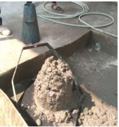
[image:2.595.308.556.52.244.2]As per IS 10262: 2009, a mix proportion was suitably designed based on the material properties of the ingredients in concrete such as specific gravity, water absorption of aggregates, cement and based on the minimum requirements of the final concrete. The design mix obtained was 1:1.79:3.01. Test on fresh and hardened concrete were performed. The slump obtained for the M20 mix designed was 65mm and is shown in Fig 2. Concrete cubes of size 150 × 150 × 150 mm were casted and 28 days compressive strength test as per IS 516-1959 have been carried on the specimens. The average 28 day compressive strength obtained was 29.29 Mpa . The testing of specimen using compression testing machine is shown in Fig 3.
Fig-2: Slump obtained for M20 concrete
Fig -3: Compression test on cube
The design of plinth beam was carried out conforming to IS 456-2000. The size of the beam was fixed as 1.5m x .2m x .2m. 2 no.s of 10mm dia HYSD bars were provided as main reinforcement. 2 legged 8mm dia vertical stirrups were provided as shear reinforcement and 2 no.s of 8mm dia bars were provided at top to support the stirrups. The detailing of the plinth beam is shown in Fig 4.
Fig -4: Detailing of plinth beam
The panels are placed on the plinth beam after curing the beams for 28days. The panels were placed on the plinth beams and first and fourth cavities were filled with m20 concrete and reinforced with HYSD bar of 10mm dia. The infill concrete is cured using gunny bags which were wetted at regular intervals. The specimens placed on the plinth beam are shown in Fig 5.
[image:2.595.350.528.373.446.2] [image:2.595.60.266.522.742.2] [image:2.595.327.538.564.746.2]© 2019, IRJET | Impact Factor value: 7.211 | ISO 9001:2008 Certified Journal | Page 5225
2.1 Test Setup
The panels were tested in loading frame of 500kN capacity. The panels were placed above two steel sections. Fig 6 shows a schematic diagram of test setup. A vertical restraint with roller arrangement was made at the top right corner of the panels to prevent the panels from lifting up due to the application of the lateral load. This also allows the horizontal movement of the panels when lateral load is applied. The lateral load was applied at one third height of the panel by a manually operating hydraulic jack of capacity 500 kN. The hydraulic jack is provided through a load cell of capacity 500kN.
In fig 6, 1 refers to the hydraulic jack; 2 refers to vertical support; 3 refers to dial gauge at top and mid height of the panel; 4 refers to the loading frame.
Fig-6: Schematic representation of Test setup
The panel was tested under repeated lateral load at a load interval of 10kN. The testing of the panels is shown in Fig 7 and Fig 8.
Fig-7: Testing of panel without openig
Fig-8: Testing of panel with opening
3. RESULT AND DISCUSSIONS
Experimental testing was done for the panel without opening first, under repeated lateral load at an interval of 10kN. 45° shear cracking developed before peak load was achieved. Specimens reached the peak load when visible longitudinal shear cracks developed accompanied by sound of plaster tearing off at the longitudinal crack. The lateral load dropped quickly when the longitudinal cracks were developed. Visible 45° shear crack occurred at 84kN at the 7th cycle ie. 82.3% of the peak load. Longitudinal shear crack
occurred at 100kN. Peak load was 102kN ad the corresponding deformation was 5.4mm. Fig 9 shows the crack pattern and fig 10 and fig 11 shows the load – deformation graph obtained at top and mid height of the panel.
© 2019, IRJET | Impact Factor value: 7.211 | ISO 9001:2008 Certified Journal | Page 5226
Fig-10: Top- load v/s deformation graphFig-11: Mid- load v/s deformation graph
Then the panel with central opening was tested under repeated lateral load at an interval of 10kN. The behavior of the panel with opening was observed to be similar to panel without opening. Corner of the openings started to crush. Diagonal cracks occurred prior to longitudinal shear cracking, First visible 45° shear crack occurred at 56kN in the 5th cycle i.e at 66% of the peak load. Longitudinal cracks
started to develop at 84kN. Peak load was 86kN and the corresponding deformation was 7.3mm. . Fig 12 shows the crack pattern and fig 13 and fig 14 shows the load – deformation graph obtained at top and mid height of the panel.
Fig-12: Crack pattern of panel with opening
Fig-13: Top- load v/s deformation graph
Fig-14: Middle- load v/s deformation graph
4. CONCLUSIONS
This experimental study was intended to study the performance and failure pattern of the panels when subjected to lateral loading. The following observations were made:
Visible 45° shear crack developed before peak load was reached in all specimens
Failure of panel without occurred by longitudinal crack at the rib of panel at concrete core.
Longitudinal crack occurred in the panel due to the slip of concrete inside the core.
The lateral load carrying capacity of panel without opening decreased by 17.65% when a central opening was provided. To increase the load carrying capacity of panel with opening, suitable low cost filler material may be used in the cores adjacent to the opening.
REFERENCES
© 2019, IRJET | Impact Factor value: 7.211 | ISO 9001:2008 Certified Journal | Page 5227
[2] S Paul and D Menon (2017), “Sustainable, rapid andaffordable mass housing using ‘gfrg’ panels”, International Journal of Advances in Mechanical and Civil Engineering, Volume: 4,135-139
[3] A Deshwali (2017), “Seismic Evaluation of GFRG Panel and Brick Infill Step-Back Set-Back and Step-Back Building”, IJSRSET, Volume: 3,614-618
[4] M Saed (2016), “Development for Sustainable Construction System Glass Fiber Reinforced Gypsum (GFRG) in Egypt Using Nanotechnology” American journal of environmental protection, Volume: 5, 82-89
[5] Philip Cherian (2016) “Mass Housing Using GFRG Panels: A Sustainable, Rapid and Affordable Solution”, The institution of engineers (India), Springer
[6] SK Subhan Alisha(2016), “Low cost housing by using GFRG panels”, IJSRSET, Volume:2,939-946
[7] B P Alias(2014), “Study of GFRG Panel and Its Strengthening”, International Journal of Civil and Structural Engineering Research, Volume:2, 162-165