-CRD-5400
SCSI RAID Controller
OEM Manual
~U~CMD
§
ETECHNOLOGr~~~~~
CRD-5400
SCSI RAI D Controller
OEM Manual
CMD Technology, Inc. 1 Vanderbilt
Irvine, California 92718 (714) 454-0800
Trademarks and Copyright
CMD, CMD Technology, and CRD-5400 are trademarks of CMD Technology, Inc. All other product and company names are trademarks or registered trademarks of other manufacturers.
Copyright © CMD Technology, Inc. January 1996. All rights reserved.
CMD reserves the right to make changes to this manual and the equipment described in this manual without notice. CMD has made all reasonable efforts to ensure that the information in this manual is accurate and complete. CMD will n,ot be liable, however, for any technical or editorial errors or omissions made in this manual, or for incidental, special, or consequential damage of whatsoever nature, resulting from the furnishing of this manual, or operation and performance of equipment in connection with this manual.
FCC Notice
This equipment has been tested and found to comply with the limits of a Class A digital device, pursuant to Part 15 of the FCC rules. These limits are designed to provide reasonable protection against harmful interference in a residential installation. This equipment generates, uses and can radiate radio frequency energy and, if not installed and used in accordance with the instructions, may cause harmful interference to radio communications. However, there is no guarantee that interference will not occur in a particular installation. If this equipment does cause ha.rnU"ul interference to radio or television reception, which can be determined by turning the equipment off and on, the user is encouraged to try to correct the interference by one or more of the following measures:
• Reorient or relocate the receiving antenna.
• Increase the separation between the equipment and receiver.
• Connect the equipment into an outlet on a circuit different from that to which the receiver is connected.
• Consult the dealer or an experienced radio/TV technician for help.
Any changes or modifications not expressly approved by the manufacturer could void the user's authority to operate the equipment.
Warranty
CMD Technology warrants this product to be free of defects in materials and/or workmanship for a period of 3 years from the date of purchase. If the product proves to be defective within the warranty period, CMD Technology will either repair or replace it. This warranty covers defects incurred in normal use only. Defects, malfunctions, or failures resulting from accidents, misuse, or mishandling are not covered. In the event that this product must be repaired or replaced, please contact CMD for an RMA number.
Important
Table of Contents
1 System Integration Issues
1-1
1.1 Cabinet Integration ... 1-1
1.1.1 Mounting Screws ... 1-2
1.1.2 Ventilation ... , ... 1-2
1 .1 .3 Silencing the Alarm ... 1-2
1.2 Board Connectors ... 1-2
1.3 Cache ... 1-7
1.3.1 How To Order SiMMs ... , ... 1-7
1.3.2 Installing SiMMs ... 1-8
1.4 Fan ... 1-9
2 Special Controller Parameters
2-1
2.1 Accessing Special Parameters ... 2-1
2.2 Vendor Parameters ... 2-1
2.3 Mode Parameters ... 2-2
3 SCSI Commands
3-1
3.1 Test Unit Ready (OOh) ... 3-1
3.2 Rezero Unit (01 h) ... 3-1
3.3 Request Sense (03h) ... 3-2
3.3.1 Extended sense data format ... 3-2
3.3.2 Sense Data Explanations ... P . . . 3-3
3.3.3 Sense Keys ... 3-4
3.3.4 Sense and Subsense Codes ... 3-4
3.4 Format Unit (04h) ... 3-7
3.5 Read (OSh) ... 3-S
3.6 Write (OAh) ... 3-S
3.7 Seek (6) (OBh) ... 3-S
3.S Inquiry (12h) ... 3-9
3.8.1 Data Descriptions ... : ... 3-10
CRD-5400
3.9 Mode Select (15h) ... ~ ... 3-11
3.9.1 Header ... 3-12
3.9.2 Block Descriptor ... 3-12
3.9.3 Page Descriptors ... 3-13
3.9.4 CRD-5400 Mode Select Parameters ... 3-13
3.10 Reserve Unit (16h) ... 3-14
3.10.1 Logical unit reserve function ... 3-14
3.10.2 Reservation right and third party reserve function ... 3-14
3.10.3 Superseded Reserve ... 3-14
3.11 Release.Unit (17h) ... 3-15
3.11.1 Third party release ... 3-15
3.12 ' Mode Sense (1Ah) ... ~ ... 3-15
3.12.1 Header ... 3-17
3.12.2 Block descriptor ... 3-18
3.12.3 Page descriptor ... 3-18
3.13 Start/Stop Unit (1 Bh) ... 3-18
3.14 Send Diagnostic (1 Dh) ... 3-18
3.15 Prevent Allow Medium Removal (1 Eh) ... 3-19
3.16 Read Capacity (25h) ... 3-19
3.17 Rea~ Extended (28h) ... 3-20
3.18 Write Extended (2Ah) ... 3-20
3.19 Seek (10) (2Bh) ... 3-21
3.20 Write and Verify (2Eh) ... 3-21
3.21 Verify (2Fh) ... 3-22
3.22 Read Defect Data (37h) ... 3-22
4 SCSI. Messages
4-1
4.1 Command Complete (OOh) T ... 4-1
4.2 Save Data Pointer (02h) T ... 4-1
4.3 Disconnect (04h) T ... 4-1
4.4 Initiator Detected Error (05h) I ... 4-1
4.5 Abort (06h) I ... 4-2
4.6 Message Reject (07h) lIT ... 4-2
CRD·5400
4.8 Message Parity Error (09h) I .• ~ ... 4-3
4.9 Bus Device Reset (OCh) I ... 4-3
4.10 Abort Tag (ODh) I ... 4-3
4.11 Clear Queue (OEh) I ... 4-3
4.12 Queue Tag Messages ... 4-4
4.12.1 Head of Queue Tag (021 h) I ... 4-4
4.12.2 Ordered Queue Tag (022h) I ... 4-4
4.12.3 Simple Queue Tag (020h) 1fT ... , ... .4-4
4.13 Identify (80h to FFh) lIT ... 4-5
4.14 Synchronous Data Transfer Request (lIT) ..•...•...•....•...••..•.••....•.•.•...•... 4-5
4.14.1 Data transfer mode parameters ... .4-5
4.14.2 Message exchange procedures for initiator ... , ... .4-6
4.14.3 Validity of data transfer mode ... 4-7
4.15 Wide Data Transfer Request (lIT) ... 4-7
CRD·5400
1
System Integration Issues
1.1 Cabinet Integration
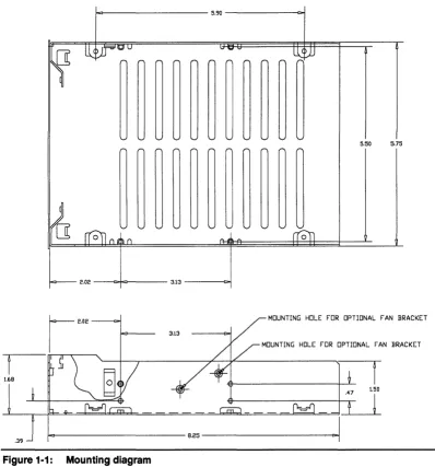
The CRD-5400 is designed to fit in any standard enclosure built to accommodate 5.25-inch form factor devices. Figure 1-1 shows the relevant chassis dimensions for mounting in an enclosure.
1 < 1 - - - -5.90 - - - i r : > j
5.50 5.75
o
----c:+=r----3.13 - - - r : > j
MOUNTING HOLE FOR OPTIONAL FAN BRACKET
3.13
MOUNTING HOLE FOR OPTIONAL FAN BRACKET
[image:8.613.152.550.249.676.2]~---8.25---~
Figure 1-1: Mounting diagram
CRD-54oo
1.1.1 Mounting Screws
To secure the CRD-5400 within an enclosure, drive screws through the enclosure's rails and into the four holes on the bottom or the four holes drilled on the side of the CRD-5400. Screws driven into the bottom should be no longer than 5/16 inch. Screws driven into the sides should be no longer than 1/4 inch. Longer screws can damage the circuitry inside the controller.
1.1.2 Ventilation
Be sure to leave enough space above the CRD-5400 box to ensure that the controller's fan can provide adequate air flow to the components inside the box.
CMD recommends a minimum vertical clearance of 1.0 inch above the box. No ventilation space is required below the controller.
Make sure the enclosure housing the CRD-5400 has its own ventilation system, preferably a fan and vent system that pulls fresh air through the front and exhausts hot air through the back. The CRD-5400 comes with a fan that attaches to the chassis on a bracket. This fan should be used to supplement the enclosure's ventilation system. It is not designed to provide adequate air flow by itself.
Important
Failure to use the fan and bracket assembly that comes with the CRO-5400 or a similar measure to dissipate the heat generated by the controller will void the warranty.
A two-level temperature sensor will monitor any heat build-up inside the CRD-5400. When the temperature reaches the fIrst level, the alarm will sound every two seconds. In such an event, you should take immediate steps to cool the unit or shut the system down in an orderly fashion. If the temperature climbs to the second level, the alarm will sound twice a second. The CRD-5400 will complete any pending I/O activity and then accept no more instructions from the host.
1.1.3 Silencing the Alarm
The CRD-5400's alarm will sound when the temperature at the controller approaches the operational limit. It
will also sound when the power supply voltage drops below 4.80 volts or exceeds 5.25 volts. You may silence the alarm by pressing Ctrl-x on the monitor keyboard. Or by pressing both the up and down arrow buttons on the front panel at the same time.
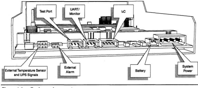
1.2 Board Connectors
CRD·5400
Figure 1·2: Back panel connectors
System Power: Provides 12±10% volts DC (3 amps maximum) to power the battery charger and fan,
also provides 4.80 to 5.25 volts DC (4.5 amps maximum) to power the controller's systems and the disk channels' terminator resistors. The controller's systems draw a steady 2.5 amps. The terminator resistors can . draw anywhere from zero to 2.0 amps from one instant to the next. The amount of current drawn by the
terminator resistors depends on conditions beyond the CRD-5400's control, such as the RAID level of the RAID sets attached to the controller and the character of the data being written to or read from the RAID sets.
If the voltage on the 5-volt line dips to 4.80 volts or climbs to 5.25 volts, the controller will sound its alarm and record the event in the event log. If the power continues to fall to 4.75 volts or climb to 5.30 volts, the controller will shut down.
The pinout for the system power connector is show below.
o
0
GND
~J
Battery: Connects to a 6.6 volt DC, lead-acid gell pack backup battery with a capacity in the range of 4 to
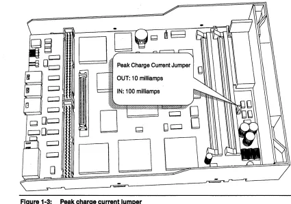
34 amp hours. The CRD-5400 will trickle-charge the battery during normal operation. The recharge rate is set by the peak charge jumper shown in Fig. 1-3. Insert the jumper shunt for a 100 milliamp peak charge current. Remove the jumper shunt for a 10 milliamp peak charge current.
The following diagram shows the pinout of the connector.
~
~
Warning
The CRD-5400 will not operate unless it is connected to a battery backup or uninterruptible power supply (UPS). CMD Technology recommends that you make sure that your battery is fully charged before connecting it to the controller. Since the CRD-5400 trickle charges the battery, it can take several hours to fully charge a depleted battery. If power is interrupted to the controller, data is . exposed and vulnerable without an adequate battery backup.
CRD-5400
o
D:;;:=.;.---=.·~
.:~:::: Peak Charge Current JumperOUT: 10 milliamps
IN: 100 milliamps
o
[image:11.612.104.529.73.372.2]DO
Figure 1·3: Peak charge current Jumper
CJ
DeJ
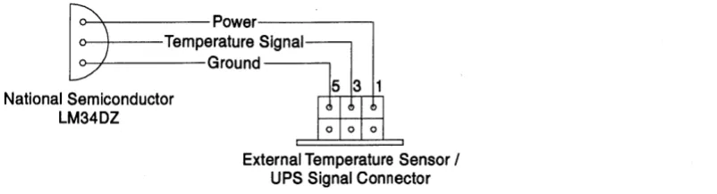
External Temperature Sensor and UPS Signal Connector: This connector does double duty. The odd pins may be used to attach an external temperature sensor to supplement the CRD-5400's internal temperature sensor. The even pins make it possible to bring critical status signals from an uninterruptible power source (UPS) unit into the controller. The following diagram and table show the pinout of the connector.
531
I : I : I : I
6 4 2
The top row of pins are for connecting external temperature sensor .
. Pin Description
1 Temperature Sensor: Power
3 Temperature Sensor: Signal Input
[image:11.612.50.534.80.738.2]5 Temperature Sensor: Ground
CRD-5400
~~'::'::
Signal~~round----'
National Semiconductor
LM34DZ
[image:12.613.145.546.77.185.2]External Temperature Sensor / UPS Signal Connector
Figure 1-4: External temperature sensor wiring diagram
The bottom row of pins are for connecting a UPS. The current CRD-5400 firmware responds to both the AC power failure and UPS "two minute" warning signals by flushing its cache and refusing to accept additional commands from the host.
Pin Description
2 UPS: low battery ''two minute" warning (5 milliamps max., low true)
4 UPS: AC power fail (5 milliamps max., low true)
6 UPS: Ground
Inter-Integrated Circuit (12C) Connector: This is used for the environmental control system (ECS), which will be implemented in a future fIrmware release. The pinout of the connector is shown in the following diagram.
vee
DATA
UART Connector: This is used to connect an external monitor to the controller. The CRD-5400's monitor utility offers a means to confIgure the controller, create and manage RAID sets, initiate rebuild operations, and view error logs, among other functions. The following diagram shows the pinout of the UART connector and how the signals should be carried to DB-25 and DB-9 connectors.
eRD-5400
>tn "E~a
CJa:F
('I)C\I,.... Grd7
I
Lo
0°JI
Recv3 Trans 2 CRO-5400 UART Port
r----
0 0 0 0 0 0 0 0 0 0 0 0•
0 0 0 0 0 0 0•
0•
0 0 ~ Male 08-25 Grd5 Recv3 Trans 2•
o•
•
o o o o o Male 08-9CMD Test Port: This is intended for use by CMD service personnel and has no application during nonnal operation of the controller.
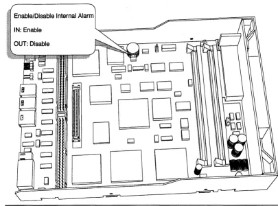
External Alarm: You may connect an auxiliary alann to the controller to supplement or replace the internal alann The external alann circuit should comply with the following power specifications.
Voltage 28 volts max. AC or DC
Current 150 milliamps max.
An opto-isolator in the controller makes it possible to use either AC or DC on the external alann circuit, as the following schematic diagram shows:
~
» 6~---~ ~~nt~rnal
Alarm Connector1- _ External Alarm Connector
Pin 2
CRD-5400
Enable/Disable Internal Alarm
IN: Enable
[image:14.613.137.542.72.372.2]OUT: Disable
Figure 1-5: Enabling and disabling the Internal alarm
1.3 Cache
The CRD-5400's cache accepts as many as four standard SIMMs for up to 256 megabytes of read and write memory.
Note
The CRD-5400 will not operate without at least one SIMM installed in the cache.
1.3.1 How To Order SIMMs
When you purchase SIMMs, they should meet the following specifications.
Speed 60 nanoseconds
Refresh Rate 2ms
Bus Width 36 bits wide
Pins 72
Capacity 4 to 128 megabytes
IC Count Not more than 36 chips
Parity ''True'' parity
CRD·5400
Note
The CRD-5400 does not support SIMMs with more than 36 integrated DRAM circuits (ICs) on
board. Check your larger SIMMs, in particular any 128 MB SIMMs, to make sure they don't carry
more than 361Cs. The CRD-5400's self-test will reject SIMMs that do not support '1rue" parity. These SIMMs do not store parity. Instead, they calculate parity on the fly for each read and write from cache, report the result to the initiator, and then discard the value.
The capacity of 36-bit-wide SIMMs may not be apparent from the listings in merchandise catalogs. Use the following table as a guide.
Configuration Size Configuration Size
1 x36 4 megabytes 8x36 32 megabytes
2x36 8 megabytes 16 x36 64 megabytes
4x36 16 megabytes 32x36 128 megabytes
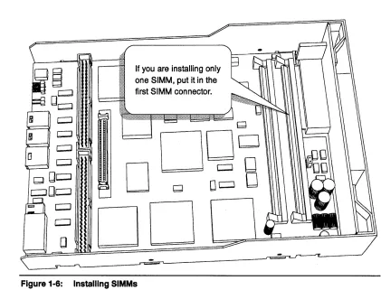
1.3.2 Installing SIMMs
The CRD-5400 requires the installation of at least one SIMM to operate, and that SIMM must be installed in the slot closest to the front panel. You may install a second SIMM in the adjacent slot, but this slot need not
be populated.
Warning
[image:15.612.119.540.393.714.2]Be sure to remove all power (including battery power) to the controller before installing SIMMs. Before you touch a SIMM, discharge any static electricity on your body by touching an unpainted metal surface.
Figure 1-6:
If you are installing only one SIMM, put it in the first SIMM connector.
Q
DOD
D
Qo~
8
DO
CRD-5400
1.4 Fan
The cooling fan is an essential component of the CRD-5400. Without it, the controller can overheat, which will trigger the warning alarm and ultimately cause the controller to shut itself down.
[image:16.615.148.543.175.443.2]The fan is mounted in a special bracket, which attaches to the sides of the controller tray with a pair of screws. The fan's power cable connects to the header at W8, as shown in Figure 1-7.
Figure 1-7: Cooling Fan Power Connection
eRD-5400
2 Special Controller Parameters
Vendor Parameters
This chapter describes CRD-5400 parameters that are designed to be accessed by vendors only. These parameters can be changed only through the monitor utility and only after you enter a special vendor password. When you have secured "vendor privileges" by entering the vendor password, the special parameters will appear in the Setup Parameters screen. Users who do not enter the vendor password will not
see these parameters.
2.1 Accessing Special Parameters
To gain access to the special parameters, enter your vendor password instead of your user password when prompted on the monitor utility's title screen.
The default vendor password is "vendor." Use the default password the first time you access the special parameters. Once you have "vendor privileges," you can change your vendor password by selecting in succession "System Functions," "Change Password," and "Vendor Password" in the monitor utility. The steps for changing your password are the same as those described in the CRD-5400 User's Manual for changing the user password. Your vendor password may contain up to nine alphanumeric characters.
If password protection is disabled, you may force the CRD-5400 to prompt you for a password at the title screen by pressing Ctrl-P. Enter your vendor password, and you will have immediate access to the special parameters. This saves the extra steps involved in entering the monitor utility to enable password protection and then backing out to the title screen to enter your vendor password.
Once you have modified the special parameters, you may restore the monitor utility to its standard user level by pressing Ctrl-Z until the title screen reappears. At this point, any user who enters the monitor utility without providing the vendor password will not have access to the special parameters.
The special parameters show up in the Setup Parameters screen. Moni tor Utility
MAIN MENU
+- - - --+ I RAID Set Information I I Setup Parameters I I Syst+---+
I RAID I Host Parameters I I Systl System Parameters I I Diskl Host LUN Mapping I I Rebu I Channel Settings I I Even I Vendor Parameters I
+ - - - - -I Mode Parameters I +- - - --+
02-21-96 12:37:29
UP ARROW: CURSOR UP I DOWN ARROW: CURSOR DOWN I ENTER: SELECT I CTRL-Z: EXIT
2.2 Vendor Parameters
The Vendor Parameters option takes you to a screen where you can enter your own name and model number for the CRD-5400. Once you change these parameters, the information you enter will be displayed on the title screens of the front panel and monitor utility. You may also specify the strings the controller will return in response to a SCSI Inquiry command.
eRD-5400
Moni tor utility VENDOR PARAMETERS
+- - - -+- - - --+ I Parameter I Value I 1---1---+ I System Display Vendor Name I cmd technology I I System Display Model Name I '(714)454-0800 I I Inquiry Response Vendor Name I cmd-tech I I Inquiry Response Model Name I crd-5400 I +- - - -+- - - --+ ARROW KEYS: MOVE CURSOR I ENTER: SELECT I CTRL- Z: EXIT
2.3 Mode Parameters
02-20-96 11:57:24
The Mode Parameters screen provides a means to change the saved SCSI mode parameters related to the physical attributes and data format of the disk array or the SCSI bus disconnect/reconnect process timing and error recovery procedure to the host. The default values are designed to be compatible with the majority of host systems. There is the possibility, however, that some hosts will not communicate properly with the CRD-5400, unless these parameters are modified.
Warning
Do not attempt to change any mode parameter values unless you are familiar with SCSI mode parameters, or you are directed to by an authorized technical support engineer.
The following is an example of the Mode Parameters screen:
Monitor utility MODE PARAMETERS
Channel 0
02-09-96 13:04:33
+- - -+- - -+- - - --+
I I I Byte I
+---+---+--+--+--+--+--+--+--+--+--+--+--+--+--+--+--+--+--+--+--+--+--+--1 I I I 21 31 41 51 61 71 81 91101111121131141151161171181191201211221231 +---+---+--+--+--+--+--+--+--+--+--+--+--+--+--+--+--+--+--+--+--+--+--+--1 I I 1 I 26 1B OC 00 00 00 00 00 00 00 I I I 2 100 00 00 00 00 00 00 00 00 00 00 00 00 00 I I I 3 100 00 00 00 00 00 00 00 00 40 02 00 00 00 00 00 00 00 00 00 00 00 I I P I 4 100 00 10 10 00 00 00 00 00 00 00 00 00 00 00 00 00 00 00 00 00 00 I I a I 7 100 00 00 00 00 00 00 00 00 00 I I g I 8 104 00 00 00 00 00 00 00 00 00 I I e I 9 100 00 00 00 00 00 I I I A 100 10 00 00 00 00 I I I B 100 00 00 00 00 00 I I I C 100 00 00 00 00 00 00 00 00 00 00 00 00 00 00 00 00 00 00 00 00 00 I +---+---+---+ N: NEXT CH I P: PREV CH I ENTER: SELECT I S: SAVE I D: DEFAULT I CTRL-Z: EXIT
3 SCSI Commands
SCSI Commands
3.1 Test Unit Ready (OOh)
Byte\Bit 7
I
6I
5I
4I
3I
2I
1I
00 OOh
1 LUN
I
02 0
3 0
4 0
5 0
The Test Unit Ready command confmns that the logical unit is ready. If the logical unit is ready, the CRD-5400 returns a GOOD status. Otherwise, the CRD-5400 reports a CHECK CONDmON status. The sense data that is generated indicates the current status of the CRD-5400.
3.2 Rezero Unit (01 h)
Byte\Bit 7
I
6I
5I
4I
3I
2I
1I
00 01h
1 LUN
I
02 0
3 0
4 0
5 0
The CRD-5400 does not implement the rezero unit command. When issued this command by the host, the CRD-5400 takes no action and responds with a GOOD status.
CRD-5400
3.3 Request Sense (03h)
Byte\Bit 7
I
6I
5I
4I
3I
2I
1I
aa a3h
1 LUN
I
a2 a
3 a
4 Allocation length in bytes
5 a
The REQUEST SENSE command enables the initiator to request sense data resulting from a CHECK CONDmON status on the prior command. The CRD-5400 retains the sense data until the initiator requests it or until the same initiator issues another command to the same logical unit, at which time the sense data will be cleared.
The CRD-5400 does not send a CHECK CONDITION status in response to a request sense command made in error, unless the error was a fatal error. Examples of fatal errors include a nonzero reserved bit in the command descriptor block, an unrecovered parity error on the data bus, or a CRD-5400 malfunction that prevents the return of sense data. Sense data may be invalid following a fatal error on a request sense command.
Byte four of the command specifies the allocation length, which is the number of bytes the initiator has allocated for returned sense data. In the case of the CRD-5400, the allocation length should always be at least 18 bytes for the initiator to receive all sense data. Any other value indicates the maximum number of bytes that shall be transferred. The CRD-5400 tenninates the Data In phase when allocation length bytes have been transferred or when all available sense data have been transferred to the initiator, whichever is less.
3.3.1
Extended sense data format
SCSI Commands
CRD-5400
Extended Sense Data
Byte\Bit 7 6
I
5I
4 3I
2I
1I
00 Valid Bit 1 1 1 0
Error Class
1 0
Segment Number
2 0 0
I
0I
0 Sense KeyFilemark EOM III
3 Information Byte (MSB)
4 Information Byte
5 Information Byte
6 Information Byte (LSB)
7 Additional Sense Length
8 0
9 0
10 0
11 0
12 Additional Sense Code (ASC)
13 Additional Sense Code Qualifier (ASCQ)
14 FRU Code
15 FPV C/D
I
0 BPVI
Bit Pointer16 Field Pointer (MSB)
17 Field Pointer (LSB)
18-n Product Unique Sense Data
3.3.2 Sense Data Explanations
Valid Bit: This bit will be one if the information bytes (bytes 3-6) are valid and zero if they are not valid.
Error Class: Ones in these three bits indicate that extended sense is in use.
Segment Number: All bits contain zeros.
Filemark: This bit is always set to zero for the CRD-5400.
BOM: This is the "end of medium" indicator and is always set to zero for the CRD-5400.
ILl: The "incorrect length" indicator is always set to zero for the CRD-5400.
Sense Key: Indicates the CRD-5400's general error categories, which are listed in the next table. The additional sense code in byte 12 gives additional information about errors.
Information Bytes: When the valid bit is one, the information bytes will contain the the sense key's unsigned logical block address associated. The information bytes will contain the address of the current logical block unless otherwise specified.
Additional Sense Length: The length in bytes of additional sense data to follow. The allocation length in the command descriptor block must be sufficient to accommodate the additional sense data to avoid truncation.
Additional Sense Code/Additional Sense Code Qualifier: When the sense key is valid, gives additional information about errors.
FRU Code: The field replaceable unit code is for the use of field service personnel only.
CRD-5400
FPV: When the field pointer valid bit is set to orie, the C/O bit and bytes 16 and 17 are valid. These fields will be ignored when the FPV bit is zero.
C/D Bit: When the command/data bit is set to one, the value in the field pointer bytes identifies the byte number in the COB that prompted an illegal request sense key. When the C/O bit is zero, the value reported in the field pointer bytes identifies the byte number in the data phase that prompted an illegal request sense key.
Field Pointer (MSB & LSB): When an illegal request sense key is issued due to an illegal parameter, this field gives the parameter's location in the command descriptor block or the data block. The next table provides detailed information about this field.
BPV: When the bit pointer valid bit is one, the next field-the bit pointer field-is valid.
Bit Pointer Field: This field pinpoints the bit that caused the illegal request sense key. A value of seven means the leftmost bit caused the error, and a zero means the rightmost bit caused the error. The byte in which the bit lies is identified by the field pointer field.
3.3.3 Sense Keys
Sense Name Explanation
0 NO SENSE No particular sense key is present.
1 RECOVERED ERROR The last executed command completed successfully with some recovery operation performed by the CRD-5400. When two or more errors occur and are recovered during processing of a command, the last is reported.
2 NOT READY The disk drive is not accessible.
3 MEDIUM ERROR An unrecoverable error was detected due to a defect in the medium or an error in the recorded data.
4 HARDWARE ERROR The CRD-5400 detected the hardware error to which the recovery process cannot be applied during command execution or self-diagnostic test.
5 ILLEGAL REQUEST An illegal value was detected in the CDB, in the parameter transferred, or the LUN is incorrect. When the CRD-5400 detects an illegal parameter in the CDB, the CRD-5400 terminates the command without rewriting the disk.
6 UNIT ATTENTION The UNIT ATTENTION condition occurred.
B ABORTED COMMAND The CRD-5400 abnormally terminated the command being executed. Normally, the initiator can try recovery by reissuing the command.
E MISCOMPARE Source data did not match the data read from medium.
3.3.4 Sense and Subsense Codes
ASC ASCQ Name Explanation Sense Key
00 00 No additional sense No particular sense code is present 0 information
An attempt was made to read the read 7 prohibited area.
00 06 1/0 process terminated The 1/0 process has been terminated by a 0 ''Terminate 1/0 Process" message.
01 06 No index/sector signal The index or sector signal was not detected 4 in the specified period.
eRD-5400
complete in the specified period.
03 00 Peripheral device write fault Write operation to the disk abnormally 4 terminated.
04 00 Logical unit not ready, The disk drive is not accessible. 2 cause not reportable
04 04 Logical unit not ready, The drive is not accessible because it is 2 format in progress being formatted.
08 01 Logical unit not ready, A timeout occurred on a drive's internal 2 format in progress interface.
08 02 Logical unit communication A parity error occurred on a drive's internal 2 parity error interface.
09 00 Track following error The track crossing pulse was detected 4 during the track following state.
DC 01 Write error recovered with The error at write operation was recovered 1
auto reallocation by the automatic alternate block allocation.
DC 02 Write error, auto The automatic alternate block allocation 3,4 reallocation failed process failed during the write operation.
10 00 I D CRC or ECC error A CRC error was detected in the ID field. 1,3
11 00 Unrecovered read error An unrecoverable error was detected when 3 data was read.
11 04 Unrecovered read error, The automatic alternate block allocation 3 auto reallocation failed. process failed during the read operation.
12 00 Sync byte not found for I D Sync byte of the I D field cannot be 1,3
field detected.
13 00 Sync byte not found for Sync byte of the data field cannot be 3
data field detected
14 01 Record not found The desired data block (sector) could not be 3 found
15 00 Random positioning error Cylinder switching does not complete in the 1,4 specified period.
15 01 Mechanical positioning error A seek error occurred on the drive. 1,4
15 02 Positioning error detected The cylinder address of the ID field did not 1,4 by read or medium match.
15 80 Settling error After track switching/cylinder switching, the 1,4 CRD-5400 is not in an on-track state.
15 FO Calibration error The calibration seek or cylinder serve has 4 failed.
17 01 Recovered data with retries The data error was recovered by read retry. 1
17 02 Recovered read data with The data error was recovered by read retry 1 positive head offset accompanied by the head offset operation
in the positive direction (positive direction is the outer direction on the disk).
17 03 Recovered read data with The data error was recovered by read retry 1 negative head offset accompanied by the head offset operation
in the negative direction is the inner direction on the disk).
18 00 Recovered read data with The data error was immediately recovered 1 error correction applied by ECC correction.
18 01 Recovered read data with The data error was recovered by the ECC 1 error correction and retries correction after retry applied.
applied
18 02 Recovered read data with The data error was recovered by ECC 1
CRD-5400
error correction and/or correction and the automatic altemate block retries, data auto- allocation process was applied.
reallocation
18 80 Recovered read data with The data error was recovered by ECC 1 error correction and/or correction and rewriting to the same block.
retries, rewrite applied
19 00 Defect list error An error was detected when the defect list 3 (G list) was read
1A 00 Parameter list length error The initiator sent a parameter of incorrect 5 length
1B 00 Synchronous data transfer An error was detected in synchronous data 4 error transfer--either an abnormal period of ACK
signal or an ACK signal response broken REQ/ACK offset.
1C 01 Primary defect list not found An error was detected when the defect list 5 (P list) was read.
1D 00 COMPARE ERROR Miscompare during verify operation. E
20 00 Invalid command operation CDB byte 0 (operation code) is invalid 5 code
21 00 Logical block address out of A logical block address exceeding the 5 range maximum value of the drive was specified.
24 00 Invalid field in CDB Setting in the CDB is incorrect. 5
25 00 Logical unit not supported Invalid LUN was specified. 5
26 00 Invalid field on parameter Setting of the parameter list transferred 2 list from the initiator during command execution
is invalid.
27 00 Write protected An attempt was made to write in the write- 7 prohibited area.
29 00 Power-on, RESET, or BUS State immediately after power-on, state 6 DEVICE RESET occurred after RESET condition, or BUS DEVICE
RESET message.
2A 00 MODE parameters changed Another initiator changed the MODE 6 SELECT parameter value.
2A 02 Log parameters changed Log parameters have changed by another 6 initiator.
31 00 Medium format corrupted The medium format is different from the 3 original one. (Formatting was not performed
after the data format setting was changed with the MODE SELECT command.)
32 00 No defect spare location No useable alternate block area is present, 4 available or the alternate block process cannot be
performed due to overflow of the control table.
32 01 Defect list update failure Updating of the defect list (G list) failed. 4
37 00 Rounded parameter The MODE SELECT parameter specified 1 by the command was rounded.
3D 00 Invalid bits in IDENTIFY 1 was specified for the reserve bit of the 5
message IDENTIFY message.
3E 00 Logical unit has not self- The CRD-5400's initial setup operation is 2 configured yet not complete.
SCSI Commands
CRD·5400
40 nn Diagnostic failure on An error was detected in self-diagnostic 4 component "nn" test.
43 00 Message error The message sent from the CRD-5400 was 8 rejected.
44 00 Internal target failure A hardware error was detected in the 4 CRD-5400.
45 00 Select/reselect failure Response waiting timeout for the initiator 1,8 was detected in RESELECTION phase.
47 00 SCSI parity error A parity error was detected in the SCSI 1,8 parity data bus.
48 00 INITIATOR DETECTED The INITIATOR DETECTED ERROR 1,8 ERROR message received message was received from the initiator.
49 00 Invalid message error Unsupported or illegal message was 8 received.
4C 00 Logical unit failed self- The CRO-5400's initial setup failed. 4 configuration (System space information could not be
read).
4C 80 Initial seek failed Initial seek failed and the initial setup of the 4 CRO-5400 cannot be performed.
4E 00 Overlapped commands A new command was issued from the same 8 attempted initiator to the same logical unit before
execution of a command was completed with tagged queuing disabled.
58 01 Threshold condition met Log parameter threshold condition has 6
been met.
5C 00 Rotational Position Locking Status of the spindle synchronization 6
(RPL) status changed function has changed.
5C 01 Spindles synchronized All spindles have synchronized. (In an array 6
environment).
5C 02 Spindles have lost All spindles in an array did not achieve 6
synchronization synchronization in the required time or at least one spindle lost synchronization.
3.4 Format Unit (04h)
8yte\8it 7
I
6I
5I
4I
3I
2I
1I
00 04h
1 LUN
I
02 0
3 0
4 0
5 0
The CRD-5400 does not implement the fonnat unit command. When issued this command by the host, the CRD-5400 takes no action and responds with a GOOD status.
CRo-5400
3.5 Read
(OSh)
Byte\Bit 7
I
6I
5I
4I
3I
2I
1I
00 08h
1 LUN
I
Logical block address (MSB)2 Logical block address
3 Logical block address (LSB)
4 Transfer block count
5 0
The read command transfers data from the CRD-5400 to the initiator. The first block of data read is specified in the logical block address field of the COB. The command continues transferring data in contiguous logical blocks until it reaches the transfer block count specified in byte 4.
If the transfer block count field is set to zerot the read command returns 256 logical data blocks. If the field is
set to a number other than zerot the command transfers that number of logical blocks.
3.6 Write (OAh)
Byte\Bit 7
I
6I
5I
4I
3I
2I
1I
00 OAh
1 LUN
I
Logical block address (MSB)2 Logical block address
3 Logical block address (LSB)
4 Transfer block count
5 0
The write command instructs the CRD-5400 to write data sent by the initiator to the array. The data is written in contiguous logical blockst starting with the logical block specified in the logical block address
field of the CDB and comprising the total number of blocks specified in the transfer block count field.
If the transfer block count field is set to zerot the command transfers 256 logical data blocks to the array. If
the field is set to a number other than zerot the command transfers that number of logical blocks.
3.7
Seek (6)
(OBh)
Byte\Bit 7
I
6J
5I
4I
3I
2I
1I
00 OBh
1 LUN
I
Logical Block Address (MSB)2 Logical Block Address
3 Logical Block Address (LSB)
I
LSB4 0
SCSI Commands
CRD-5400
The CRD-5400 does not implement the seek (6) command. When issued this command by the host, the CRD-5400 takes no action and responds with a GOOD status.
3.8 Inquiry (12h)
Byte\Bit 7
I
6I
5I
4I
3I
2I
1I
0 12h
1 LUN
I
02 0
3 0
4 Allocation Length in Bytes
5 0
The Inquiry command requests information about the identity and characteristics of the CRD-5400.
0
This command executes successfully even in the presence of a Unit Attention condition. It also executes if
the CRD-5400 is not ready or if the specified LUN is invalid.
The following situations will cause a CHECK CONDITION status to be reported and an abnormal termination:
• The CDB contains a specification error in other than the LUN field. • A CRD-5400 hardware error makes the inquiry data inaccessible.
• An unrecoverable error is present on the SCSI bus. • The overlap command's exception conditions are applied.
Standard Inquiry Data
Byte\Bit 7 6 5 4 3 2 1
0 Qualifier Device type code
0 0
1 RMB Device type qualifier
0 0
2 ISO Vers ECMA Version ANSI Version
0 0 0
I
1I
3 AENC TmlOP Response Data Format
0 0
I
0I
0 0I
0I
1I
4 1 Fh (Additional data length)
5 0
6 0
7 Reladr WB32 WB16 Sync Linkd CmdQue
0 0 0 1 0 0 1
8-15 "CMD TECH" (Vendor ID in ASCII)
16-31 "CRD-5400" (Product ID in ASCII)
32-35 Microcode version in ASCII Product Revision in ASCII
0
0
0
SfRe
0
CRD-5400
3.8.1
Data Descriptions
Qualifier
000 The type of 1/0 device represented by the specified logical unit matches the "device type code" field. The logical unit does not need to be ready for this code to be sent.
001 The type of 1/0 device represented by the specified logical unit matches the "device type code" field
011 The specified logical unit is not being supported. The "device type code" field indicates 1 Fh when this code is sent.
Device type code
00000 Direct access device
11111 Undefined device
RMB bit
0 When equal to 1, the storage medium is replaced. The CRD-5400 acts as a fixed disk, so this bit is always
o.
Device type qualifier
000000 All bits are set to
o.
SCSI standard version010 The second byte in the data block represents the SCSI standard recognized by the CRD-5400. Since the CRD-5400 is a SCSI-2 device, it reports "010" for ANSI X3T9.86.
ISOVers
0 Always set to zero.
ECMA Version
0 Always set to zero.
AENC
0 Asynchronous Event Notification Capability. The CRD-5400 does not support this function.
TmlOP
0 Terminate 1/0 Process message. The CRD-5400 does not support this message.
Response data format
0010 The format of the Inquiry data is identified by this field. The CRD-5400 reports all data in SCSI-2 format, so this field will always equal "0010."
Additional data length
1Fh The length of bytes of additional inquiry data to follow.
RelAdr
0 Relative Logical block addressing. The CRD-5400 does not support this function.
WBus32
0 Data transfers take place on a 32-bit-wide bus. The CRD-5400 does not support this function.
WBus16
0 Data transfers take place on a 16-bit-wide bus. The CRD-5400 does not support this function.
Sync
1 Synchronous-mode data transfer. The CRD-5400 supports this function.
Linked
0 Command linking. The CRD-5400 does not support this function.
CmdQue
SCSI Commands
CRO-5400
SftRe
0
I
Soft RESET condition. The CRD-5400 does not support this function.Vendor 10
CMD TECH
I
This field indicates the product supplier's name in left-justified ASCII code and will always contain "CMD TECH."Product 10
CRD-5400
I
This field indicates the product model name in left-justified ASCII code and will always contain "CRD-5400."Product revision
I
This field contains the CRD-5400 microcode revision number in ASCII code.3.9 Mode Select (15h)
Byte\Bit 7
I
6I
5I
4I
3I
2I
1I
00 15h
1 LUN
I
PFI
0I
SP2 0
3 0
4 Parameter list length
5 0
The Mode Select command allows the initiator to configure various CRD-5400 parameters.
When the page format bit in byte 1 of the CDB is 1, the initiator is signaling that is transferring parameters in the page descriptor format.
The save pages (SP) bit in byte 1 of the CDB controls whether the parameters in the command will be saved on the disk array. An SP bit of 1 will prompt all parameters to be saved on the execution of the command. If
the SP bit is 0, the parameters will not be saved.
The parameter list length field specifies the length in bytes of the parameter list being transferred from the initiator. When this field is 0, no data is transferred and the command terminates with no error reported. All parameter lists must conform to the format and length specified in the "Mode Select Parameters" table later in this section.
A parameter list length that does not exactly equal the actual length of the parameter list being transferred causes the command to terminate. All parameters that were transferred before the termination are invalid, and the CRD-5400 reports a CHECK CONDITION status (ILLEGAL REQUEST Invalid Field in CDB).
There are three types of mode select parameter values: current values, save values and default values. The current values are the parameters that actually control the CRD-5400 and are what the mode select command changes. The save values are those parameters that have been specified by the mode select command and saved on the disk array. The default values serve as current values immediately after power-up and until any saved values can be read. If there are no saved values, the default values remain in effect until a mode select command is issued.
The current values are initialized to the saved values at power-on, when a RESET occurs, or when the CRD-5400 receives a BUS DEVICE RESET message. If there are no saved values, the current values are initialized to the default values.
If the mode select command modifies a parameter page that is common to all initiators, UNIT A TfENTION conditions (MODE parameters changed) occur for all the initiators except the initiator issuing the command.
CRD-5400
If the mode select command seeks to change an unchangeable parameter, the command will terminate with a CHECK CONDmON status (ILLEGAL REQUEST Invalid field in parameter list). In this case, all parameters specified by the initiator will be invalid.
The next three tables show the proper configuration of a mode select parameter list. A complete parameter list comprises a four-byte header, an eight-byte block descriptor, and one or more page descriptors. Also acceptable are parameter lists consisting of only a four-byte header and one or more page descriptors. The initiator may transfer the header only or the header and block descriptor only.
Header
Byte\Bit 7
I
6I
5I
4I
3I
0 OOh
1 OOh (medium type)
2 device-specific parameter (OOh)
3 OOh/08h (block descriptor length)
Block Descriptor
Byte\Bit 7
I
6I
5I
4I
3I
0 OOh
1 Data block count (MSB)
2 Data block count
3 Data block count (LSB)
4 OOh
5 Data block length (MSB)
6 Data block length
7 Data block length (LSB)
Page Descriptor
Byte\Bit 7
I
6 5I
4I
3I
0 0 Page Code
1 Page length
2-n Parameter field
3.9.1 Header
Medium Type: OOh (default type) must be specified in this field. Device-Specific Parameters: OOh must be specified in this field.
2
I
1I
02
I
1I
02
I
1I
0Block Descriptor Length: The length (in bytes) of the block descriptor to follow is specified in this field. Do not include the length of the page descriptors. The CRD-5400 recognizes only one block descriptor. When a block descriptor is included, specify 08h in the block descriptor length field. When the initiator is sending a parameter list containing only a header followed by page descriptors, specify OOh in the block descriptor length field.
3.9.2 Block Descriptor
SCSI Commands
CRO-54oo
Data Block Count: Specify the total number of logical blocks allocated to the user space on the disk array. When this field is zero, all user spaces set by the format parameter and drive parameter are configured with the logical data blocks. This field must be zero.
Data Block Length: The length (in bytes) of the logical data blocks on the disk is specified in this field. The CRD-5400 requires that the logical data block length be equal to the physical data block length.
3.9.3 Page Descriptors
A page descriptor comprises a page code byte, the page length byte, and a parameter field. Each parameter function attribute is specified on a separate page. The initiator can use the MODE SELECT command to specify one page descriptor or two or more page descriptors in an arbitrary order.
Page Code: Specifies the page descriptor type indication code (page number).
Page Length: Specifies the length (in bytes) of the parameter field. The length excludes the page header, so measurement begins from byte 2. The value that the initiator specifies for this field must equal the page length sent by the CRD-5400 in response to a MODE SENSE command.
3.9.4 CRD-5400 Mode Select Parameters
The following table lists the contents and length of the parameter list that is transferred from the initiator to the CRD-5400 with the MODE SELECT command. If the initiator specifies a page descriptor that is not supported by the CRD-5400, the command will terminate with a CHECK CONDmON status (ILLEGAL REQUEST Invalid field in parameter list) and all parameters specified in the command will be invalidated.
Parameter (page number) Length
Header (Mode Select/Mode Select Extended) 4
Block descriptor 0/8
Read/write error recovery parameter (01) 12
Disconnect/reconnect parameter (02) 16
Format parameter (03) 24
Drive parameter (04) 24
Verify error recovery parameter (07) 12
Caching parameter (08) 12
Peripheral device page (09) 8
Control Mode page (OA) 8
Medium support page (OB) 8
Notch page (OC) 24
All page descriptors supported (3F) 1521160
CRD-5400
3.10 Reserve Unit (16h)
Byte\Bit 7
I
6I
5I
4I
3I
2I
1I
00 16h
1 LUN
I
3rd ptyI
3rd pty Oev 10I
02 0
3 0
4 0
5 0
The reserve unit command enables individual initiators in a multiple initiator environment to reserve logical units in the disk array. An initiator may also use this command to reserve a logical unit for another SCSI device.
3.10.1
Logical unit reserve function
This command reserves the entire logical unit specified in the CDB for the exclusive use of the initiator until the reservation is superseded by another reserve unit command, the initiator issues a release unit or priority reserve command, a bus device reset message is issued by any initiator, a reset condition occurs, or power to the CRD-5400 is recycled.
When an initiator issues this command for a LUN that is already reserved by another initiator, the command terminates with RESERV A TION CONFLICT status.
Once an initiator has reserved a LUN, the CRD-5400 rejects any commands other than INQUIRY, REQUEST SENSE and RELEASE UNIT from any other initiator and reports a RESERV A TION CONFLICT status. The INQUIRY and REQUEST SENSE commands execute normally. The RELEASE UNIT command terminates with a GOOD status, but the CRD-5400 ignores the command if the initiator does not have the reservation right.
3.10.2 Reservation right and third party reserve function
If the 3rd Pty bit of CDB byte 1 is 0, the initiator reserves the specified LUN on the CRD-5400 and claims the reservation right for the same LUN.
If the 3rd Pty bit is 1, the initiator reserves the specified LUN on the CRD-5400 for another SCSI device, which is identified by its SCSI ID in the 3rd Pty Dev ID bit of the CDB. The reservation right always stays with the initiator, even though the LUN on the CRD-5400 is reserved for another device. The CRD-5400 maintains the LUN reservation until it is superseded by another valid Reserve command from the initiator that made the reservation or until it is released by the same initiator, by a Bus Device Reset message from any initiator, or by a "hard" Reset condition.
3.10.3 Superseded Reserve
An initiator may modify the reservation it holds by issuing another, superseding Reserve command for the same logical unit. Upon the successful execution of the superseding Reserve command, the reserved state of the CRD-5400 will conform to the new command. If the superseding Reserve command cannot be executed, the reserved state is unchanged. The superseding Reserve command permits the initiator to reserve the CRD-5400 for another SCSI device, without relinquishing its reservation right.
The following examples will help to further explain reservation rights and third party reservations.
CRD·5400
with a RESERVATION CONFLICT status. TheO RELEASE UNIT command tenninates successfully, but the CRD-5400 takes no action in response.
Example 2: Initiator-A gives the RESERVE UNIT command containing a 3rd Pty bit of 1 and the 3rd Pty Dev ID for targetlinitiator-l, initiator-A reserves the CRD-5400 for targetlinitiator-l but retains the reservation right for the CRD-5400. In this situation, if target/initiator-l tries to send a RESERVE UNIT command, the CRD-5400 rejects the command with a RESERVATION CONFLICT status. A RELEASE UNIT command from targetlinitiator-l tenninates nonnally, but the CRD-5400 disregards it. Initiator-A can issue the INQUIRY, REQUEST SENSE, RELEASE UNIT or RESERVE UNIT commands to the
CRD-5400, but other commands are rejected with a RESERVATION CONFLICT status. A RELEASE UNIT command from initiator-A clears the reserved state of the CRD-5400, and a RESERVE UNIT command changes the reserved state of the CRD-5400. If any other initiator attempts to issue any commands other than INQUIRY, REQUEST SENSE or RELEASE UNIT, the CRD-5400 will respond with a
RESERV A TION CONFLICT status. A RELEASE UNIT command from any other initiator terminates nonnally, but the CRD-5400 disregards it.
3.11 Release Unit (17h)
Byte\Bit 7
I
6I
5 4 3I
2I
10 17h
1 LUN 3rd Pty 3rd Pty Dev I D
2 X
I
x
I
x
x
x
I
x
I
x
3 OOh
4 OOh
5 0
0
0 X
The RELEASE UNIT command ends the initiator's reservation of a CRD-5400 logical unit. If an initiator attempts to release a logical unit that it has not reserved, the CRD-5400 just disregards the command and returns a GOOD status.
3.11.1 Third party release
When the 3rd Pty bit of the CDB is 0, the command releases the specified logical unit that the initiator reserved with a previous RESERVE UNIT command that also had a 3rd Pty bit of O.
When the CDB's 3rd Pty bit is 1, the command releases the specified logical unit, but only if the reservation was made using the third party reservation option by the initiator that is requesting the release, and for the same SCSI device specified in the third party ID field.
3.12 Mode Sense (1Ah)
Byte\Bit 7
I
6I
5I
4I
3I
2I
1I
00 1Ah
1 LUN
I
0I
DBDI
02 PC
I
Page Code3 0
4 Transfer byte length
5 0
CRD·5400
The mode sense command returns the values of various parameters related to the physical attributes and data
format of the disk array or the SCSI bus disconnect/reconnect process timing and error recovery procedure to the initiator.
The data the CRD-5400 sends to the initiator in response to this command consists of a header, block descriptor, and one page descriptor for each parameter specified.
The Disable Block Descriptors (DBD) bit of byte 1 in the CDB controls whether the mode sense data
returned will contain a block descriptor. If this bit is 0, the response will contain a header, block descriptor and one or more page descriptors. If this bit is 1, everything but the block descriptor will be sent.
The page code of the page descriptor is specified in the page code field in byte 2. The following table lists the parameters supported by the CRD-5400 and their page codes.
Parameter (page number) Length
Header (Mode Select/Mode Select Extended) 4
Block descriptor 0/8
Read/write error recovery parameter (01) 12
Disconnect/reconnect parameter (02) 16
Format parameter (03) 24
Drive parameter (04) 24
Verify error recovery parameter (07) 12
Caching parameter (08) 12
Peripheral device page (09) 8
Control Mode page (OA) 8
Medium support page (OB) 8
Notch page (OC) 24
All page descriptors supported (3F) 1521160
If the value of the page code field is 3Fh, all page descriptors supported by the CRD-5400 are sent to the initiator. If the value is not 3Fh and is associated with a parameter supported by the CRD-5400, the page descriptor for that parameter is sent. If the value identifies a parameter that the CRD-5400 does not support, the command terminates with a CHECK CONDmON status (ILLEGAL REQUEST Invalid field in CDB).
The Page Control (PC) field of CDB byte 2 specifies the type of page descriptor parameter value sent by the mode sense command. The following table lists the PC values supported by the CRD-5400.
PC Type of parameter sent to Initiator
00 Current value: The CRD-5400 responds with the current value of each parameter. The current values can be set in three ways:
1 ) by a successful execution of the mode select command;
2) by retrieving the saved values of the mode parameters if a MODE SELECT command has not successfully completed since the last power-on, hard RESET condition, or BUS DEVICE RESET message;
3) or by being initialized with the default values at power up if no saved values are present.
01 Changeable value: This value indicates the parameter field/bits that may be changed on the CRD-5400. A changeable field/bit position will be indicated with a 1. A field/bit that cannot be changed will be represented with a O.
10 Default value: The CRD-5400 responds with the default value of each parameter.
SCSI Commands
CRD-5400
The transfer byte-length field specifies the total number of bytes of mode sense data transferred. The CRD-5400 transfers the number of bytes of mode sense data set by the page code field, or the amount of mode sense data that is specified in the transfer byte-length field, whichever is smaller to the initiator. When the transfer byte-length field is set to 0, no data is transferred and the command terminates.
The following table illustrates the configuration of the parameter list resulting from a mode sense command. Each parameter lists comprises a 4-byte header, 8-byte block descriptor and one or more page descriptors. If
the DBD bit is set to 1, the block descriptor is not sent. The page descriptor is not sent when the page code is set to OOh.
Header
Byte\Bit 7
I
6I
5I
4I
3I
2I
1I
a
a
Sense data length1 OOh (medium type)
2
a
3 OOh/OSh (block descriptor length)
Block descriptor
Byte\Bit 7
I
6I
5I
4I
3I
2I
1I
a
a
OOh1 Number of data blocks (MSB)
2 Number of data blocks
3 Number of data blocks (LSB)
4 OOh
5 Data block length (MSB)
6 Data block length
7 Data block length (LSB)
Page descriptor
Byte\Bit 7 6 5
I
4I
3I
2I
1I
a
a
PSa
Page Code1 Page Length
2-n Parameter Field
3.12.1 Header
Sense data length: This field gives the length (in bytes) of the parameter list compiled in response to the mode sense command. The length is measured from byte 1 of the header and does not include the length of the sense data length field itself. The CRD-5400 reports the length of the parameter lists required to fully satisfy the mode sense command. To ensure that all parameter lists have been received, the initiator should compare the value of this field with the transfer byte-length field of the sense data CDB. If the sense data length plus the length of the sense data length field itself is greater than the transfer byte-length value, then the initiator received a truncated mode sense parameter list.
Medium type: OOh (default type) is always reported to this field.
Block descriptor length: This field denotes the length in bytes of the block descriptor. The measurement does not include the header or page descriptor. When the DBD bit is 0, the CRD-5400 reports 08h in this field to inform the initiator that a set of block descriptors follows the header. When the DBD bit is 1, the CRD-5400 reports OOh in this field.
CRD-5400
3.12.2 Block descriptor
Number of data blocks: This field indicates the number of logical blocks available to the user in the logical
unit. Any spare sectors set aside for the alternative block process will not be included in this value. Data block length: This field denotes the length in bytes of each logical block.
3.12.3 Page descriptor
The descriptor for each page of mode parameters begins with a 2-byte header, followed by the parameter field.
PS bit: When set to one, the Parameters Savable (PS) bit denotes that the page has savable parameters. When set to 0, the PS bit indicates that none of the parameters contain within the page are savable. All page parameters supported by the CRD-5400 can be saved.
Page length: This field denotes the length in bytes of the parameter field, excluding the page header and page descriptor.
Parameter field: Byte 2 and succeeding bytes indicates the parameter values corresponding to the type requested in the page control field of the CDB.
3.13 Start/Stop Unit (1 Bh)
Byte\Bit 7
I
6I
5I
4I
3J
2I
1I
00 1Bh
1 LUN
I
0I
Immed2 0
3 0
4 0
I
Start5 0
When issued this command by the host, the CRD-5400 takes no action and responds with a GOOD status.
3.14 Send Diagnostic (1 Dh)
Byte\Bit 7
I
6I
5I
4I
3I
2I
1I
00 1Dh
1 LUN
I
02 0
3 0
4 0
5 0
SCSI Commands
CRD-5400
3.15 Prevent Allow Medium Removal (1Eh)
Byte\Bit 7
I
6I
5I
4I
3I
2I
1I
0 1 Eh
1 lUN
I
02 0
3 0
4 0
I
5 0
The CRD-5400 does not implement the prevent allow medium removal command. When issued this command by the host, the CRD-5400 takes no action and responds with a GOOD status.
3.16 Read Capacity (25h)
Byte\Bit 7
I
6I
5I
4I
3I
2I
1I
0 25h
1 lUN
I
02 0
3 0
4 0
5 0
6 0
7 0
8 0
9 0
0
Prevent
X
0
The Read Capacity command permits the initiator to request information about the capacity of a CRD-5400 logical unit.
The format of the data returned by the read capacity command is as follows:
Byte\Bit 7
I
6I
5I
4I
3I
2I
1I
00 logical block address (MSB)
1 logical block address
2 Logical block address
3 logical block address (lSB)
4 Block size (MSB)
5 Block size
6 Block size
7 Block size (lSB)
CRD·5400
3.17 Read Extended (28h)
Byte\Bit 7 1 6 1 5 1 4
I
3 .1 2 1 1 10 28h
1 LUN 1 0
2 Logical block address (MSB)
3 Logical block address
4 Logical block address
5 Logical block address (LSB)
6 0
7 Transfer block count (MSB)
8 Transfer block count (LSB)
9 0
Like the read command, the read extended command transfers data to the initiator; however, the read extended command accepts a four-byte logical block address and a two-byte transfer block count. The logical block address field indicates the frrst logical block in the transfer. The command transfers a contiguous set of logical blocks, the number of which is determined by the transfer block count field.
0
If the logical block address and transfer block count fields describe a transfer that exceeds the maximum number of logical blocks on the CRD-5400, the command terminates with a CHECK CONDITION status (ILLEGAL REQUEST Logical block address out of range) and abort the disk read operation.
3.18 Write Extended (2Ah)
Byte\Bit 7 1 6 1 5 1 4 1 3 1 2 1 1 1 0
0 2Ah
1 LUN
I
02 Logical Block Address (MSB)
3 Logical Block Address
3 Logical Block Address
5 Logical Block Address (LSB)
6 0
7 Transfer block count (MSB)
8 Transfer block count (LSB)
9 0
The write extended command transfers data from the initiator to the CRD-5400, but unlike the write command, it accepts a four-byte logical block address and a two-byte transfer block count. The logical block address field indicates the first logical block in the transfer. The command transfers a contiguous set of logical blocks, the number of which is determined by the transfer block count field.
If the logical block address and transfer block count fields describe a transfer that exceeds the maximum number of logical blocks on the CRD-5400, the command terminates with a CHECK CONDmON status (ILLEGAL REQUEST Logical block address out of range) and aborts the operation.
SCSI Commands
CRD-5400
3.19 Seek (10) (2Bh)
Byte\Bit 7
I
6I
5I
4I
3I
2I
1I
00 2Bh
1 lUN
I
02 Logical Block Address (MSB)
3 Logical Block Address
3 logical Block Address
5 logical Block Address (lSB)
6 0
7 0
8 0
9 0
The CRD-5400 does not implement the seek (10) command. When issued this command by the host, the CRD-5400 takes no action and responds with a GOOD status.
3.20 Write and Verify (2Eh)
Byte\Bit 7
I
6I
5I
4I
3I
2I
1I
00 2Eh
1 lUN
I
02 logical block address (MSB)
3 logical block address
4 logical block address
5 logical block address (lSB)
6 0
7 Transfer block count (MSB)
8 Transfer block count (lSB)
9 0
The CRD-5400 does not support verification of data. This command is treated like a write extended (2Ah) command.