Efficient Image Stitching in the Presence of
Dynamic Objects and Structure Misalignment
Chao Tao1, Hanqiu Sun2, Changcai Yang1, Jinwen Tian1
1
The Institute for Pattern Recognition and Artificial Intelligence, Huazhong University of Science and Technology, Wuhan, China;
2
The Department of Computer Science and Engineering, The Chinese University of Hong Kong, Shatin, Hong Kong (China). Email: [email protected]
Received March 9th, 2011; revised April 20th, 2011; accepted April 29th, 2011.
ABSTRACT
This paper presents a new method for simultaneously eliminating visual artifacts caused by moving objects and struc- ture misalignment in image stitching. Given that the input images are roughly aligned, our approach is implemented in two stages. In the first stage, we discover motions between input images, and then extract their corresponding regions through a multi-seed based region growing algorithm. In the second stage, with prior information provided by the ex- tracted regions, we perform a graph cut optimization in gradient-domain to determine which pixels to use from each image to achieve seamless stitching. Our method is simple to implement and effective. The experimental results illus- trate that the proposed approach can produce comparable or superior results in comparison with state-of-the-art me-thods.
Keywords: Image Stitching, Motion Estimate, Region Growing, Graph Cut
1. Introduction
Image stitching refers to creating a high-resolution pano- rama that seamlessly combines two or more images with overlapping fields of view [1]. There are many good ex- isting methods for creating pleasing panoramas. However, they usually have a number of requirements to produce satisfactory results: limited camera translation, limited motion of objects in the scene and similar exposure set- tings between images.
Generally, there are three problems which often occur in the field of image stitching, namely exposure differ- ence, structure misalignment and ghosting artifacts. In this paper, we are concentrating with two of them, one is ghosting effect caused by moving objects within a scene, and the other is structure misalignment in the overlapped region, which is usually due to inaccuracy of registration methods, motion parallax and etc.
For the problem of de-ghosting, Uyttendaele etc pro- pose to use regions of difference [2]. This technique identifies dynamic objects by checking the source images to see where pixels differ by more than a threshold, and then decide which objects to keep and which ones to erase using a weighted vertex cover algorithm. This al- gorithm works well, but it may fail when images are not prior well-registered and exposure correction. In addition,
it does not establish the correspondence for regions re- lating to the same object. Thus, ambiguous situation may occur when multiple moving objects exist in the scene. Another technique with excellent results is proposed by Agarwala [3]. Its main idea is to place a seam along the edges of objects in the picture, and then pick pixels from one photo or another based on which side of the seam they fall. Similar works have also been done in [4,5]. However, these techniques require the user manually labels all regions of moving objects, therefore is not suitable for our goal of a fully automated solution.
After extensively reviewing the previous work on mis- alignment correction and de-ghosting, we can find that existing approaches have its own advantages as well as disadvantages. Moreover, we did not find any work in the literature, which can simultaneously deals with both of them. In this paper, we propose a novel technique to address them together. After detecting feature corre- spondence between two images, the first step is to dis- cover motions by interactively applying Random Sample Consensus (RANSAC) [11] in a divide and conquer manner. Once motions are found, we take feature pixels belonging to them as seed points, and use a region grow- ing method to roughly extract moving objects. However, to completely remove ghosting artifacts, we have to ac- curately determine which regions in the input images are not static. To this end, we formulate it as a labeling problem, and remove ghosting artifacts and structure misalignment together via graph cut. The paper is or- ganized as follows. Section 2 gives the detail of the pro- posed algorithm. The experimentation results are pro- vided in Section 3, followed by conclusions in Section 4.
2. Our Image Stitching Algorithm
For clarity, in this paper, we consider the basic case of stitching two roughly aligned images. Our algorithm is implemented in two stages. In the first stage, we discover the motions between two input images, and then extract their corresponding regions. With prior information pro- vided by the extracted regions, the second stage is to find an optimal seam, which can simultaneously eliminate visual artifacts caused by the moving objects and struc- ture misalignment. We formulate the task as a labeling problem, and solve it by graph cut. The following sec- tions describe the details of the algorithm.
2.1. Motion Discovery
Let us denote the two images to be stitched as IS and T
I , and assume that feature correspondence between them has been already established through Scale-invari- ant feature transform (SIFT) matching [12]. To extract motions between them, we cluster the correspondence by interactively applying RANSAC in a divide and conquer manner. More specifically, we first select the homogra- phy with largest no. of coincident key points. Then we remove these points and apply RANSAC again in the remaining points until the no. of points to be matched is below some threshold.
The above process is similar to the work of [13] and [14]. Different from them, before implementing RANSAC, we remove mismatches by our previous proposed method [15]. The reason is, from our experiment, we found that the stability of result is very poor if there exists lots of mismatches in the correspondences, especially when we
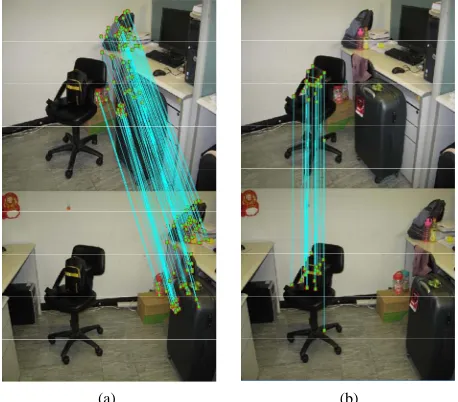
try to find multiple motion models in them. The output of this stage is a set of motions, in which the one with larg- est no. of coincident image points corresponds to the background (the global background motion), and the others correspond to the moving objects (the local mo- tion). Figure1 shows an example scene, where two mo- tions are detected by fitting two homography transforma- tions to the feature matches. One for the background (Figure1(a)), the other for the chair (Figure1(b)).
2.2. Locating Moving Region
After finding a set of motions, the next step is to find their corresponding regions, so as to using pixel values from only one of the contributing images for them to eliminate ghosting artifacts. This task can be solved by multiple-seeds based region growing algorithm [16].
Formally, assuming there are N local motions found in the last step and each local motion i is defined by a homography transformation i
m
H with associated feature correspondence
x yik, ik
, where 1 . Similarly, the global background motioni
N
g
m is denoted by a ho- mography transformation Hg with associated feature correspondence
xkg,ykg
. Next, for each mi, we take
x yki, ki
as seed points, and gradually grow them by including neighboring pixel , which obey one of the following criteria:p
Criteria 1: Motion cues
We assume that the background is dominant in the scene. Based on this assumption, motion cues are defined as the discrepancy between the local motion and the
[image:2.595.309.538.458.659.2](a) (b)
global background motion, which is written as:
S T i S T g
I p I f p I p I f p (1) where fi
p and fg
p are mapping functions gen- erated by location motion mi and global motion mg, which map the pixel p in IS, to the fi
p andg
inf p
IT respectively. Their definitions are as fol- lows:
if p Hip (2)
gf p Hgp (3)
Criteria 2: Color similarity
1
( ) ( )
S S
I p I seed
(4)
Here, 1 stands for the intensity threshold.
The advantage of using both cues is two fold: on one hand, motion cues can effectively determine the neigh- boring pixels which have the consistent motion with the seed. On the other hand, the color similarity ensures the extracted region smooth and complete, in case using ob- ject motion information alone can only detect a part of the moving object. We run the region growing algorithm twice. The first time is to generate a set of region
1 2
R Rs, s,,RNs
in IS. Similarly, the second time is to generate a set of
1, 2, ,
T T T
N
R R R in IT with the in- verse motion filed relating IT and IS. Accordingly, the applied region growing criteria are changed to (5) and (6) as follows:
1
T p S i p T S g
I I f I p I f1 p (5)
1T T
I p I seed (6) where
i and1
i p p
f H fg
p Hg1p. To conclude, the result of this stage is a set of region pair1 2
R Rs, s,,RNs
, where ands t
i i
R R are related to the regions which are consistent with motion in two images.
i
m
2.3. Optimal Seam Selection
With the information provided by the extracted regions, we can now create a seam which is able to eliminate structure inconsistence between images as well as being avoided passing through moving objects. To do so, we formulate it as a labeling problem, and solve it by graph cut. In the following, If represent the final composite image with the overlapped region . fp denotes the label for every pixel pIf , which is assigned either 0 or 1. If fp= 0, the value pixel p comes form image Is , otherwise, it comes from It
In order to make the final composite image If like as if the image were captured without the moving objects in
the scene, weuse information from only one image for each extracted region pair
R Ris, it
, and ignore corre- sponding information in the other images. In other words, we preassign the same label fp for pixels in theand
s t
i
R Ri as follows:
i
herwise
1 0 s t i pif R R f ot (7)
Next we consider the label assignment for the remain- ing pixels in , and define a objective function, E f
as the sum of two terms: a data term over all pixel
i and an interaction term
,
p q
C Vs over all pairs of
neigh-boring pixels p q, :
,
s
p p
V
d , p ) , , p, q
q
V p f p q f f
E f
(8)where the data term encourages transitions between the extracted regions and their nearby pixels to be natural and seamless. We use the following cost function to ex-press this desired property:
,
exp
22 p f d p d p V p f
(9)
where is the Gaussian scale and is set to 1 in the experiment. d
pp
f is the distance between the pixel and its nearest region that is pre-assigned with label
p
p
f . This can be calculated by distance transformation [17].
The interaction term takes gradient smoothness into account and penalizes pixel dissimilarity in the gradient domain, which makes the seam favor smooth area in and in turn reduces the structure complexity along the seam. Specifically, we define it as follows [10]:
, , ,
1 , ,
s p q
p p q
q f f
S p q if f f
if f f
m Sd
p q
0 V p q (10)
,m S T
S p q p p p p
S T
I I I I
(11)
,
d s s
S p q I p p
p p
T T
I
I I
(12)
where m and d are two costs measuring the gradi- ent smoothness and similarity between the neighboring pixels and q.
S p
S
3. Experiment Results
Having already illustrated the proposed image stitching algorithm by an example, we proceed by further demon- strating the performance of our method in two examples captured in different conditions. Comparison with other methods using our implementation is also given.
3.1. Result Analysis
We first show a simple case, where only one moving object exists in the scene. The two sources images, as shown in Figures2(a) and (b) are provided as input. Fig- ure2(c) is the initial alignment, where the visual artifact (indicated in the red box) is obvious because of moving objects and inaccuracy registration. Figures2(d) and (e) show the result of Auto Stitching [18] and Panorama Maker [19], respectively. As can be seen, although the structure misalignment is alleviated, it does not help in solve the problem of ghost effect. Figure2(f) is obtained by our method, in which only one instance of the moving object is kept in the final composite image and structures are properly aligned. This demonstrates that our method can handle moving object and structure misalignment within the same framework.
(a) (b)
(c) (d)
(e) (f)
Figure 2. (a) and (b) are the two registered images. (c) The initial alignment. (d) Auto stitching (e) Panorama factory (f) our method.
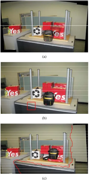
Next, we apply our algorithm to a more complicated example. This scene is challenging because it contains multiple moving objects, and also exists occlusion be-tween them. Figure 3 shows the process. Figure 3(a) and (b) are the original images. Our algorithm first de-tects motions between images, and then roughly extracts their corresponding region (one for the red box (Figure 3(c)), and the other for the bag (Figure3(d)). After that, by taking gradient similarity and transition smoothness into account, we obtain the final panoramic image by selecting an optimal seam in an intelligent manner (indi-cated by a red curve in Figure 4(c)). As can been seen, our seam favors smooth area in the overlapped region and being avoided passing through moving object. Thus, the final composite image is pleasing and structure con-sistent, while the artifacts caused by moving objects and misregistration still exist in AutoStitching (Figure4(a)) and Panorama Factory (Figure4(c)).
3.2. Computation Times
We finally discuss the computation time needed for our
(a) (b)
(c) (d)
[image:4.595.309.537.350.678.2] [image:4.595.58.289.377.677.2](a)
(b)
(c)
Figure 4. (a) AutoStitching (b) Panorama Factory (c) Out Method.
method. To give an idea for the possible reader, we con-sider the Figures 2(a) and (b) (640 × 480 pixels) as a benchmark. In reporting this result, we use a PC with an Intel Core(TM)2 Duo processor with a 2.4 GHz clock speed 1 GB RAM, and use matlab as our coding platform to perform the algorithm.
[image:5.595.79.266.84.462.2] [image:5.595.309.539.111.196.2]We tabulate the computation times for each step in Table 1. As can be seen, the total time needed for image stitching is 18.65 s. In the same setting, the time needed for AutoStitching and Panorama Factory was 12.16 s and 19.1 s, respectively. Therefore, the computation time of our method is acceptable.
4. Conclusions
A novel technique has been presented to achieve seam-less image stitching without producing visual artifacts caused by moving objects and structure misalignment. The proposed method includes two major components: 1)
Table 1. Computation time for each step of the proposed approach.
Step Computation time (second)
Motion discovery 12.52
Locating the moving region 1.78
Optical seam selection 4.35
Total time 18.65
Motion discovery 2) a graph cut based optimization framework for seamless stitching. We create data cost to ensure that transition between moving objects and their nearby pixels to be natural and seamless, and smooth cost to encourage the seam favor smooth area. Thus, moving object removal and structure correction are si-multaneously achieved within the same framework.
There are also some minor limitations for our method. First, our framework relies heavily on feature matches to extract every independent motion in the scene. Thus, it may fail when correspondence between motions are not detected. Second, our framework can not handle the ex-posure difference, which is another challenge problem in the filed of image stitching. Therefore, future work aims at making our framework robust to these phenomena, and also extending it to videos and multiple images.
5. Acknowledgements
The work was supported by the UGC grants for research (nos. 2050423, 2050454).
REFERENCES
[1] R. Szeliski, “Image Alignment and Stitching: A Tutorial,” Microsoft Research, Technical Report MSR-TR-2004-92, 2004.
[2] M. Uyttendaele, A. Eden and R. Szeliski, “Eliminating Ghosting and Exposure Artifacts in Image Mosaics,” Proceedings of the 2001 IEEE Computer Society Confer-ence on Computer Vision and Pattern Recognition, Kauai, 8-14 December 2001, pp. 509-516.
[3] A. Agarwala, M. Dontcheva, M. Agrawala, S. Drucker, A. Colburn, B. Curless, D. Salesin and M. Cohen, “Interactive Digital Photomontage,” Proceedings of ACM SIGGR- APH’04, Vol. 23, No. 3, 2004, pp. 294-302.
[4] A. Eden, M. Uyttendaele and R. Szeliski, “Seamless Im-age Stitching of Scenes with Large Motions and Exposure Differences,” 2006 IEEE Computer Society Conference on Computer Vision and Pattern Recognition, 2006, pp. 2498-2505.
[5] A. Mills and G. Dudek, “Image Stitching with Dynamic Elements,” Image and Vision Computing, Vol. 27, No. 10, 2009, pp. 1593-1602.doi:10.1016/j.imavis.2009.03.004
Texture Synthesis and Transfer,” Proceedings of ACM SIGGRAPH’01, 2001, pp. 341-346.
[7] V. Kwatra, A. Schodl, I. Essa, G. Turk and A. Bobick, “Graphcut Textures: Image and Video Synthesis Using Graph Cuts,” Proceedings of ACM SIGGRAPH’03, Vol. 22, No. 3, 2003, pp. 277-286.
[8] A. Levin, A. Zomet, S. Peleg and Y. Weiss, “Seamless Image Stitching in the Gradient Domain,” Proceedings of European Conference on Computer Vision, 2004. [9] Y. Boykov, O. Versker and R. Zabih, “Fast Approximate
Energy Minimization via Graph Cuts,” IEEE Transactions on Pattern Analysis and Machine Intelligence, Vol. 23, No. 11, 2001, pp. 1222-1329.doi:10.1109/34.969114
[10] J. Y. Jia and C. K. Tang, “Image Stitching Using Structure Deformation,” IEEE Transactions on Pattern Analysis and Machine Intelligence, Vol. 30, No. 4, 2008, pp. 617-631. doi:10.1109/TPAMI.2007.70729
[11] M. A. Fischler and R. C. Bolles, “Random Sample Con-sensus: A Paradigm for Model Fitting with Applications to Image Analysis and Automated Cartography,” Commu-nications of the ACM, Vol. 24, No. 6, 1981, pp. 381-395. doi:10.1145/358669.358692
[12] D. G. Lowe, “Distinctive Image Features from Scale-In- variant Keypoints,” International Journal of Computer Vi- sion, Vol. 60, No. 2, 2004, pp. 91-110.
doi:10.1023/B:VISI.0000029664.99615.94
[13] J. Wills, S. Agarwal and S. Belongie, “What Went Where,” Proceedings of IEEE Conference on Computer Vision and Pattern Recognition, 2003, pp. 37-44.
[14] P. Bhat, K. C. Zheng, N. Snavely, A. Agarwala, M. Agrawala, M. Cohen and B. Curless, “Piecewise Image Registration in the Presence of Multiple Large Motions,” Proceedings of IEEE Conference on Computer Vision and Pattern Recognition, 2006, pp. 2491-2497.
[15] C. Tao, Y. H. Tan, Y. T. Wang and J. W. Tian, “Discard Wide-Baseline Mismatch Using Contour Fragments,” Electronic Letters, Vol. 46, No. 12, 2010, pp. 834-835. doi:10.1049/el.2010.1128
[16] R. Adams and L. Bischof, “Seeded Region Growing,” IEEE Transactions on Pattern Analysis and Machine In-telligence, Vol. 16, No. 6, 1994, pp. 641-654.
doi:10.1109/34.295913
[17] G. Borgefors, “Distance Transformations in Digital Im-ages,” Computer Vision, Graphics, and Image Processing, Vol. 34, No. 3, 1986, pp. 344-371.
doi:10.1016/S0734-189X(86)80047-0
[18] M. Brown and D. G. Lowe, “Automatic Panoramic Image Stitching Using Invariant Features,” International Journal of Computer Vision, Vol. 74, No. 1, 2007, pp. 59-73. doi:10.1007/s11263-006-0002-3