International Journal of Engineering Inventions
e-ISSN: 2278-7461, p-ISSN: 2319-6491
Volume 7, Issue 1 Ver. II [February 2018] PP: 13-20
www.ijeijournal.com Page | 13
Experimental Investigation of Compressed Air engine
Performance
S. Allam and M. Zakaria
Automotive Technology Department, Faculty of Industrial Education, Helwan University, Cairo, Egypt. Corresponding Author: S. Allam
Abstract: As a solution of shortage of fossil fuels and the environmental legislation, compressed air as a source of energy, which can be used in different applications such as vehicles is well known as a nonpolluting fuel has attracted scientists and engineers for centuries. Efforts are being made by many researchers, developers and manufacturers to use the compressed air vehicle technology in all respects. In this paper, an effort is made to study various modifications, merits and demerits of compressed air engine. For this purpose, a single cylinder petrol engine is tested at different operating conditions using gasoline, modified to work with compressed air and tested again. All performance, emission, noise and vibration parameters are measured at different engine operating conditions.
Based on the results presented in this paper, compressed air technology is one of the best technologies and demands more attention as it tends to be eco-friendly and running on a fuel that is freely available. Even though the engines running on the compressed air seem to compare poorly to gasoline engine in range and power and their applications severely constrained due to their limited driving range, but the power to weight ratio is improved due to the reduction in engine weight. CAE will be an ideal mode of transportation if enough research and analysis are put in the field.
Keywords: Compressed Air, Global Warming, Alternative Sources of Energy, energy input, energy released, emission control.
--- ---Date of Submission 27-02-2018 ---Date of acceptance: 14-03-2018 ---
---I.
INTRODUCTIONFuel prices are going higher and higher and it will be difficult for the people to cope with these price hikes, it affects our daily life due to the increase in the transportation cost. Compressed Air Engine (CAE) is a zero-emission because the output is cooled air. There is no burning of fuel so, no heat is produced, so it helps to cutting down the carbon emissions into the atmosphere, bring down the pollution level of air and increase the engine life. This will increase the engine life with good performance; reduce the maintenance cost of the complete vehicle and no environment polluting emissions [1].
Some new technology is developed like new design of cam for four stroke engines; also provide new technology of fabrication of compressed air vehicle. It has some advantages and disadvantages of compressed air vehicle and the experimental analysis like load calculation, power production by engine and main factor is pollution is not produced by this engine. The thermodynamics of heat exchange, mechanical and aerodynamic losses, electrical efficiencies etc. all these effects may reduce the overall efficiency to 40% or less. The speed of the engine is found to increase almost linearly with the increase in the pressures. High pressure of 9 bars the maximum speed attained was 36.5 km/hr. The engine is modified from a 4-working stroke to a 2-working stroke engine (power and exhaust) by modification of cam-gear system. At 20°c, 22-liter tank loaded with air at 8 bar used just 15.6 W of vitality. The motorcycle installed with the compressed air engine can operate at maximum speed around 38.2 km/hr and distance up to 5 km. This will be produced enough power for speeds of about 15-20 kilometers per hour Compressed air engine is not producing any harmful gases for environment as well as human body this is totally pollution free engine [2].
Saurabh Pathak, et al. [2] describes the automotive industry is now using light weight vehicles as they have better handling. Heavy vehicles produce harmful gases like SO2, CO2 which is major cause of air pollution. The CAE technology is cheaper comparatively to IC engines at lower maintenance cost. The author concludes that pneumatic technology can be tested and developed using vane type noble air turbine and their efficiency varies from 72% to 47% which is very high comparatively to IC engines and the widespread of this technology helps in controlling serious problems of global warming.
obtained at maximum pressure of 8 bars and high-power gain of 0.95KW achieved at (bar at 1320 rpm. The rotating speed was found to be 715 rpm to 965 rpm whereas at high pressure of 25 bars with varying angles the speed ranges from 1191 rpm to 1422 rpm. At low pressure of 5 bars, maximum speed was 28.9 km/hr having travelling distance of 2.5 km and at 9 bars maximum speed was 36.5 km/hr travelling distance of 1.7 km.
Arjit Maurya, et. al. [4] is concerned about saving the environment and many measures are taken to reduce the pollution in environment. In compressed air technology air is taken as input from intake valve vertically above piston head and modified cam shaft is used to alter the timing of valve. Experimentally speed of 60 km/hr was achieved by the use of this engine. This engine is very efficient as it causes no combustion and therefore no harmful gases are released. The experiment which is performed shows that vehicle runs at 60 km/hr and weight was 18.5 kg which slightly affects the efficiency of engine.
An experimental analysis of a compressed air engine is presented by Qihui, and Maolin [5]. A prototype CAE system is set up to obtain performance of the CAE. The output torque, power and efficiency are obtained through experimental study. The results show that the prototype of CAE has a good economic performance under low speed, the performance of the CAE is mainly influenced by the rotation speed and supply pressure and when the supply pressure is 2 MPa, the maximum output power is 1.92 kW; the maximum output torque is 56.55 N∙m, and the maximum efficiency is 25%.
Addala and Gangada [6] examined the performance of a car which takes air as the working medium. Compressed air car is affordable and have a performance rate whose power to weight ratio stands up to 0.0373kW/kg. For arriving at a fair power to weight ratio, it has been considered possible factors which would result to minimize the weight of the car such as a3-wheeled vehicle as designed, and the entire chassis was fabricated with 1inch angular frames.
Yadav1 and Singh [7] presented a modified proto type of a horizontal, single cylinder low speed to run on compressed air. From the presented results, it can be seen that the indicated power is increasing for increase of load, as load is increased, the speed falls down, to maintain it constant injection pressure has to be increased, and as the injection pressure has to be increased, the indicated mean effective pressure gets increased; hence the indicated power is increased upon the application of the load. Though the applied load was small, however, the developed power was in proportion to the applied load. As load was applied the speed was reduced, to maintain it constant, the inlet air pressure has to be increased. As shown injection pressure is increased. In the present case the speed was maintained constant as 600 rpm. As the output speed was less the brake power was significantly lower. The mechanical efficiency is increasing with the increase of output power. At lower output it was very low.
Swapnil and Kailas [8] studied the compressed air driven vehicle, the engine used in this project is being subjected to different modifications like, Cam-shaft modification, new set of gears for camshaft and different conclusion has been drawn from the presented results, Engine speed (RPM)versus inlet pressure; as the inlet pressure increases, also engine speed increased linearly, also, as the engine torque versus inlet pressure; as the pressure increases, torque on crank shaft increased linearly, and engine torque versus engine speed; as the engine speed increases, the engine torque increased linearly.
Huang et. al. [9] presented a theoretical (using a simplified thermodynamic models) and experimental investigations of 100 cc internal combustion engine running on a compressed air at pressures ranging from 5 to 9 bar (absolute pressure). It has been shown that the highest power output of 0.95 kW was obtained at 9 bar and 1320 rpm, the highest torque of 9.99 N·m occurred at the same pressure, but at 465 rpm, the outlet pressure increased from 1.5 bar at 500 rpm to 2.25 bar at 2000 rpm, the temperature inside the cylinder decreased from room temperature to 17 °C was observed, the air consumption (flow rate) of used air engine is low, at approximately 1050 L/min, which limits its power performance, causing problems of lubrication and sealing between the piston and cylinder. It has been also shown that the efficiency of the compressed air operation is approximately 13% at 5 bar supplying air pressure while the rotation speeds is below 1500 rpm, and an approximately 2.25 bar exhaust air pressure occurs when operating at 9 bar supplying air pressure and 2000 rpm.
Mahendrakar1 and Chandan [10] have been modified the four-stroke engine to work on a six stroke, the first four stroke for gasoline and the last two for compressed air. It has been shown that use of pressure energy (Compressed Air) and Gasoline improve the Brake Thermal Efficiency (BTE) to 34% and overall efficiency of 68%, reduce the use of fossil fuel, decrease in cylinder temperature and reduce the residual of the exhaust gasses which improve the volumetric efficiency.
Design and analysis of CAE is presented by Lal, [11], it has been stated that weight of the engine is reduced to great extent that leads to, high power to weight ratio, Power loss due to inertia of the moving parts is reduced, start-up power is not required to run engine, and Exhaust air causes no harm to environment as it is cold and clean.
Experimental Investigation of Compressed Air Engine Performance
www.ijeijournal.com Page |15 optimization of CAE, a physical model of CAE is set up. To obtain performance of the CAE, a prototype CAE system is set up. And the physical model of CAE is verified by experiments. The contents of this paper are organized as follows: the introduction to CAE is represented in section 1; the engine modification, experimental procedure and assumptions are described in section 2; the experiment results are shown and analyzed in section 3; a comparison between the ICE power and the CAE power is presented in section 4, and the conclusion is stated in section 5.
II.
EXPERIMENTAL PROCEDURE AND ASSUMPTIONSTo make the present results applicable certain modifications have been made to study specific circumstances of generator air engine. During these measurements with the help of the acoustic border, four different assumptions have been addressed: 1) the atmospheric temperature variations do not affect the reading to a large extent, 2) the
inlet pressurized air temperature variations ( 2ₒC) do not affect the reading to a large extent, and 3) the engine performance remained constant for a particular load and speed [12].
2.1 Engine Specifications
A four stroke, single cylinder, air cooled petrol engine generator was loaded using an electric lamp board, equipped with all needed equipment and used through the first part of this study. The engine swept volume is163 cc, with oil tank is 0.6 liter, and its fuel consumption is 1.22 lit /hr. Generator maximum power is 2465 watt at 3800rpm, engine maximum power is 3200 watt at 3800 rpm, and power factor (pf) is 0.77. The needed measuring equipment are tachometer for engine speed, multimeter for output power, fuel metering, stopwatch for fuel consumption, pressure gages for inlet and outlet air pressure, and thermometers for inlet and outlet air temperatures.
Figure.1 Layout of the compressed air engine test rig
1) Compressed air tank, 2) pressure sensor, 3) solenoid valve, 4) Signal output,5) Power Source (24 volt), 6) ECU, 7) Input signal, 8) LDR holder ,9) LDR, 10) Tachometer, 11) Timing disc, 12) Generator, 13) Output shaft,14) Engine,15 Output cable to measure power,16) Flywheel, 17)Ammeter, 18) Voltmeter, 19) Inlet air and 20) Pneumatic hose, 21) air outlet, and 22) temperature sensor.
2.2 Engine Modifications
The engine was modified from four-stroke to two-stroke and used during the second part of this second part as shown in Figure (1). To convert the four-stroke petrol engine into two stroke compressed air engine several modifications have been done, which are listed below;
2.2.1. Cam Positions
Volume 7, Issue 1 Ver. II [February 2018] PP: 13-20
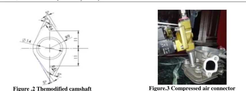
Figure .2 Themodified camshaft Figure.3 Compressed air connector 2.2.2. Intake Port Modification
The carburetor does not have any application in the engine running on compressed air, only in where air is injected from top of combustion chamber. The purpose of this modification is to provide a suitable place to inject a compressed air via a connector from the spark plug position. The connector is installed in the cylinder head with thread, the connector with an internal diameter of 12 mm and an outside 18 mm as shown in Figure (3).
Figure .4 The electronic control unit connected to electromechanical control valve.
1) Valve symbol 2/2, 2) Solenoid valve (24DC),3) Signal output, 4) Compressed air output,5) Compressed air flow, 6) Channel MOSFET RF54ON, 7) Resistor 10kΩ (1/4Watt), 8)Resistor 330Ω (1/4Watt), 9) Voltage Regulator 7805(5V, 1A), 10)Resistor 10Ω (1/4Watt) 11) Ground, 12) Resistor 10kΩ (1/4Watt), 13) Resistor 330Ω (1/4Watt), 14) Resistor 1kΩ (1/4w), 15) NPN transistor2N2219A, 16) Diode Ideal, 17) AC Voltage source, 18) Electrolytic Capacitor -2200 µf, 19) Red LED (0.2 in, 5 mm), 20) LDR (ORP12), 21) Printed Circuit Board in 2.8(W)x2.8 (H), 22) pin Terminal Block, 23) transformer, 24) holder, 25) Timing Disc, a 26)Crank shaft.
To control the on/off air flow to the engine a solenoid valve 2/2 which has an electromechanical control valve that is shown in Figure (4) was used. The valve is controlled by an electric current through a solenoid coil. The electronic unit is used to control the electrical signal of the valve, to control the close and open-air passage. The contents of electronic circuit are listed under Figure (4)
2.2.3 Piston rings
They are changed to bigger sizes 6.25 inch than the original 6 inches to fill full the piston clearance due to lower engine temperature.
2.2.4. Engine oil
Experimental Investigation of Compressed Air Engine Performance
www.ijeijournal.com Page |17
III.
RESULTS AND DISCUSSION.3.1 Petrol Engine Characteristics 3.1.1 Engine Brake Power
The measured engine brake power increases with the engine speed up to the point of maximum power and decrease after that speed as shown in Figure (5). This is due to the increase in mechanical losses, as well as the decrease in volumetric efficiency and ignition timing. The best engine performance can be obtained at full engine load and the maximum power is 3200 watts at 3800 rpm.
Figure.5 Petrol engine power and brake specific fuel consumption versus engines speed at full load.
3.1.2 Engine Brake Specific Fuel Consumption (BSFC)
It can be noted that, bsfc is affected by engine speeds and loads as shown in Figure (5). Higher engine speeds consume more fuel for the same torque because of the increasing in friction losses and decreasing in the ignition timing. It can be also noted the increase in fuel consumption at lower engine speeds produce due to the increase in heat transfer from the working fluid to the cylinder walls. Brake specific fuel consumption is decreasing at engine speed 3200 rpm to 3600 rpm.
3.2 Air Engine Characteristics 3.2.1 Air Engine Brake Power
The output power from the modified air engine was measured at different inlet air pressures (6, 7, 8 and 9) bar, and the pressure and air flow rate data were measured before the inlet of the cylinder.
Figure.6 Air engine power versus engine speed at different input pressure at full load
The relation between the engine brake power and the CAE speed is presented in Figure (6). It can be seen that the engine brake power increase with the air inlet pressure. When the engine speed increases more than
0 500 1000 1500 2000 2500 3000 3500 4000 4500 5000 0
1000 2000 3000 4000
Engine Speed (rpm)
En gi ne P ow er (Wa tt)
Petrol Engine Performance
0 500 1000 1500 2000 2500 3000 3500 4000 4500 50000.3 0.4 0.5 B SF C ( kg /k w .h r)
Measured Engine Power Simulated Engine Power Measured BSFC Best Fit BSFC
500 1000 1500 2000 2500 3000 3500 4000
0 500 1000 1500 2000 2500
Engine Speed (rpm)
E n g in e P o w e r ( Wa tt )
Measured at P= 9 bar Simulated at P= 9 bar Measured at P= 8 bar Simulated at P= 8 bar
2500 rpm the engine power decreases due to the decreasing in injecting time of a compressed air. To make it constant the pressure of the compressed air inlet must be increased. The recorded maximum power is 1735 watt at2500 rpm using constant air 9 bar is pressed.
3.2.2 Engine Specific Air Consumption.
Figure (7) shows the relation between the engine speed and the engine air flow rate. It can be seen that, the engine air flow rate increases with the engine speed as well as the inlet air pressure.
The flow rates of the compressed air engine with supplying pressure of 9 bar, vary from 630 L/min to 720 L/min as the rotation speed changes from 1000 rpm to 3500 rpm. The highest engine power output was obtained at the highest supplied air pressure, indicating that the highest air pressure provides the highest force applied on the piston.
Figure.7 Air engine flow rate versus engine speed at different loads
IV.
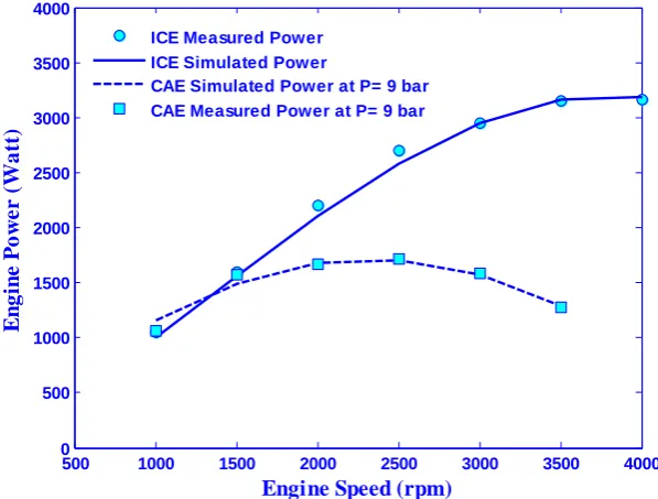
Comparison between Petrol and Compressed Air EnginesA comparison between the measured engine power for ICE fueled with petrol and that for CAE are presented in Figure (8). It can be seen from the figure that the ICE power is better than CAE especially at high engine speed. The CAE can be improved by increasing the compressed air inlet pressure as well as use a suitable control circuit to synchronize the inlet air pressure with the engine speed.
Figure.8 Air engine flow rate versus engine speed at different loads
500 1000 1500 2000 2500 3000 3500 4000
500 550 600 650 700 750 800
Engine Speed (rpm)
F
lo
w
R
ate
(L
/m
)
Me as ure d at P= 9 bar
Sim ulate d at P= 9 bar Me as ure d at P= 8 bar Sim ulate d at P= 8 bar
Me as ure d at P= 7 bar
Sim ulate d at P= 7 bar Me as ure d at P= 6 bar Sim ulate d at P= 6 bar
500 1000 1500 2000 2500 3000 3500 4000
0 500 1000 1500 2000 2500 3000 3500 4000
Engine Speed (rpm)
E
n
g
in
e
P
o
w
e
r
(
Wa
tt
)
ICE Measured Power ICE Simulated Power
Experimental Investigation of Compressed Air Engine Performance
www.ijeijournal.com Page |19
V.
CONCLUSIONS AND RECOMMENDATIONS FOR FUTURE WORK.In this study, the modification of petrol engine to work on a compressed air was done to successfully according to the following points:
1. A comprehensive study of compressed air behavior and review on compressed air engines were made and the following information was summarized; compressed air is clean, safe, simple and efficient. There are no dangerous exhaust fumes of or other harmful by products when compressed air is used because it is a non-combustible, non-polluting utility.
2. The modification of the petrol engine was made successfully according to the following steps:
The fuel tank and the carburetor were removed from the petrol engine because there is no use for them in the compressed air engine.
The spark plug was replaced with the compressed air inlet port.
Some components were added to the engine, which are important to engine like the connecting cables and the air flow control valves.
To increase the efficiency of using CAE, a suitable solenoid valve was installed on the engine to control the amount of compressed air inlet, and the inlet timing was made with a solid stick attached to the flywheel that pulls the trigger when the piston is at TDC.
3. The CAE power is increased with the compressed air pressure and the measured maximum power maximum power is 1735 watt at 2500 rpm using pressurized air of 9 bar and the maximum efficiency is 20%.
4. The inlet temperature is slightly increased as the inlet air pressure is increased and the maximum inlet temperature variation is 2° C. Also, it is increased with the engine speed and the maximum variation is 4° C at the maximum engine speed. The outlet air temperature is decreased about 6° C from 6 to 9 bars at low engine speed while it is decreased 2° C at high engine speed. The outlet air temperature is increased rapidly with the engine speed and it is varied from -10° C at speed of 1000 rpm, inlet pressure of 9 bar to 30° C at 3500 rpm. This engine need to heat exchanger to control the outlet engine temperature and avoid the ice containing around the cylinder liner.
5. Different recommendations can be suggested to improve the performance of CAE such as; lighter materials can be used to build the engine, test the engine at different conditions of inlet pressure and temperature are needed, build a full thermodynamic model for the CAE engine to optimize the engine performance based on its operating conditions.
VI.
CONFLICT OF INTERESTSThe authors declare that there is no conflict of interests regarding the published results of this article.
ACKNOWLEDGMENTS
The technical support from Eng. Ibrahim Elagouze from Automotive Department, Zagazig Advanced Technical School, Ministry of Education, Elsharkia, Egypt, is acknowledged. Also, the vital support from Dr. Ahmed Aiad, Faculty of Education, Helwan University, during writing the educational impact of this research on technical education, which is not listed in this paper is acknowledged.
REFERENCE
[1]. Pramod Kumar. AIR POWERED ENGINE. International Journal of Mechanical Engineering and Technology,Volume 7, Issue 2, March-April 2016, pp. 66–72
[2]. Saurabh Pathak, Kontham Swetha, V Sreedhar, VSV Prabhakar (2014) Compressed Air Vehicle- A Review. International Journal of Mechanical and Production Engineering 2(4): 1-5.
[3]. Ankit Sharma, Manpreet Singh (2015) Parametric Analysis Of An Air Driven Engine: A Critical Review. International Journal of Advanced Research In Engineering And Technology 6(4): 1-9.
[4]. Arjit Mourya, Arif Khan, Darshika Bajpayee, Nainsi Gupta Modified Compressed Air Engine Two Stroke Engine Working On The Design Of A Four Stroke Petrol Engine. International Journal On Theoretical And Applied Research In Mechanical Engineering 3(4), (2014).
[5]. Qihui Yu, Maolin Cai „„Experimental Analysis of a Compressed Air Engine‟‟. Journal of Flow Control, Measurement & Visualization, 2015, 3, 144-153
[6]. Addala, A., & Gangada, S. (2013). Fabrication and Testing of Compressed Air Car, Global Journal of Researches in Engineering Mechanical and Mechanics Engineering Volume 13 Issue 1, 2013.
[7]. Sharma, R., & Singla, N. Study and fabrication of compressed air engine. International Journal of Research and Development Organizations, Vol. 2, Issue 1, 2011.
[8]. Swapnil, M. M. A., Kailas, M. Compressed Air Driven Vehicle. International Journal of Technology Enhancements and Emerging Engineering Research, VOL 3, ISSUE 06, 2015.
[9]. Huang, C. Y., Hu, C. K., Yu, C. J., & Sung, C. K. (2013). Experimental investigation on the performance of a compressed-air driven piston engine. Energies, 6(3), 1731-1745.
[11]. Lal, A. (2013). Design and dynamic analysis of single stroke compressed air engine. International Journal of Renewable Energy Research (IJRER), 3(2), 315-319.
[12]. Allam '' Optimal Design of Compact Multi-Partition MPP Silencers for I. C. Engines Noise Control''. Noise Control Engineering Journal 64 (5), 615-626.