A Simple Current Control Strategy for a
Four-Leg Indirect Matrix Converter
Cristian Garc´ıa
1, Member, IEEE, Marco Rivera
2, Member, IEEE, Miguel L´opez
1, Jose Rodriguez
1, Fellow, IEEE,
Ruben Pena
3, Member, IEEE, Patrick Wheeler
4, Senior, IEEE and Jos´e Espinoza
3, Member, IEEE
1
Department of Electronics Engineering, Universidad T´ecnica Federico Santa Mar´ıa, Valpara´ıso, CHILE
E-mail: [email protected].
2
Department of Industrial Technologies, Universidad de Talca, Curic ´o, CHILE
E-mail: [email protected].
3
Department of Electrical Engineering, Universidad de Concepci´on, Concepci´on, CHILE
E-mail: [email protected].
4
Department of Electrical and Electronic Engineering, University of Nottingham, Nottingham, UK
E-mail: [email protected].
Abstract—In this paper the experimental validation of a predictive current control strategy for a four-leg indirect matrix converter is presented. The four-leg indirect matrix converter can supply energy to an unbalanced three-phase load whilst providing a path for the zero sequence load. The predictive current control technique is based on the optimal selection among the valid switching states of the converter by evaluating a cost function, resulting in a simple approach without the necessity for modulators. Furthermore, zero dc-link current commutation is achieved by synchronizing the state changes in the input stage with the application of a zero voltage space vector in the inverter stage. Simulation results are presented and the strategy is experimentally validated using a laboratory prototype.
Index Terms—AC-AC Conversion, Matrix Converter, Four Leg Converters, Current Control, Predictive Control, Modulation Schemes
NOMENCLATURE
is Source current [isA isB isC]T
vs Source voltage [vsA vsB vsC]T
ii Input current [iA iB iC]T
vi Input voltage [vA vB vC]T
idc dc-link current
vdc dc-link voltage
i Load current [iu iv iw]T
v Load voltage [vu vv vw]T
i∗ Load current reference [i∗
u i∗v i∗w]T
Cf Filter capacitor
Lf Filter inductor
Rf Filter resistor
R Load resistance L Load inductance
I. INTRODUCTION
In recent years, the interest in matrix converters applications has increased [1]–[3]. Matrix converter topologies offer an “all silicon solution” for ac-ac power conversion, achieving sinu-soidal input and output waveforms with bidirectional power flow and being capable of operating under high temperatures
and pressures [4]–[6]. Moreover, due to the absence of elec-trolytic capacitors, matrix converters could be more compact, robust and reliable when compared to conventional topologies [2].
Compared to a conventional back-to-back converter, the physical space saved by a matrix converter has been estimated as 60%. This characteristic makes the matrix converter a suitable topology for specific applications such as wind-diesel topologies, distributed generation applications, emergency ve-hicles, military and aerospace applications, external elevators for building construction and skin pass mills [2], [7], [8].
As reported in [6], there are a number of different topologies for direct ac-ac converters. Among them, the indirect matrix converter (IMC) has a similar performance to the standard direct matrix converter (DMC). The IMC is very similar to a back-to-back converter but includes bi-directional switches in the rectifier and has no dc-link capacitor. The lack of a storage element offers the possibility to reduce losses because the commutation of the input stage can be achieve with zero dc-link current [9], [10].
When energy is supplied to a three-phase load it may be necessary to take into account the unbalance nature of the load and the need for a path for the zero sequence current. This path could be provided by connecting the neutral of the load to the neutral point of a zig-zag transformer [11]–[13]. However, this topology could be costly and bulky. Another option is to use a four-leg voltage source converter (VSC) on the load side where the fourth leg would then provide the needed neutral connection for the load. As reviewed in [14], there are several topologies that can handle zero sequence voltage and current caused by an unbalanced source and/or load in three-phase four-wire systems. As reported in [15]–[18], a matrix converter can also be used to supply energy to an unbalanced three-phase load.
the carrier-based PWM technique, the 3D-SVM offers many advantages such as good dc-link utilization and minimum output distortion, but it has complex modeling and a higher computational requirements and is therefore not intuitive for implementation [21], [22].
Model predictive control (MPC) is an attractive alternative to the aforementioned classical methods due to its fast dynamic response and simple concept as well as the possibility to include constraints in the design of control. The first time that the idea of use a predictive controller for current control in power electronics was presented was in [23]. This was a unique very early paper, and very advanced for the time. This paper had a reduced impact at that time, mainly because microprocessors and the theory for predictive control were not sufficiently developed. Nowadays this idea constitutes a real alternative for the control of power converters as reported in [24]–[26]. Thanks to the sustained increase of computational power of control platforms (such as digital signal proces-sors (DSPs), field programmable gate arrays (FPGAs) and dSPACE controllers) [27], now is possible the implementation of predictive control techniques as well as other more complex techniques such as fuzzy, adaptive, sliding mode and genetic algorithms [28]–[31].
MPC techniques have been demonstrated as a potential al-ternative to control very complex power converters topologies such as matrix converters [26]. In fact, [30], [32]–[42] have been presented several implementations for direct and indirect topologies. In [32], [33], [42] a predictive current control with instantaneous reactive power minimization has been proposed for both the three-phase direct and indirect matrix converter, which has been evaluated using a clean ac-source [32], [42] and a distorted ac-supply [33]. The main issue observed was that an instantaneous reactive power minimization can obtain input currents in phase with its respective source voltage but it cannot ensures a sinusoidal waveform when distortion is presented in the ac-source. In order to solve this issue, different implementations were proposed by the authors and summarized in [38]. Among them, an active damping imple-mentation was proposed in [34], [35] to improve the input current behavior but this strategy mitigates only the current harmonics produced by the input filter and commutation of the switches but cannot mitigate any distortion of the ac-supply. An imposed waveform for the input current was proposed in [36], [37] which effectively improves the input current but at the cost of an increased switching frequency. Other techniques such a fuzzy implementation in combination with predictive control and a predictive torque control for an induction machine fed by a direct matrix converter were proposed in [30] and [40], [41], respectively, but at the cost of a more complex mathematical and prediction model.
This paper presents the experimental use of finite-set model predictive control (FS-MPC) for the current control of 4Leg-IMCs. As reported in [43]–[45], the FS-MPC utilizes an opti-mization function that considers all possible switching states. However, due to the discrete nature of the power converters and since the 4Leg-IMC has a finite number of switching states (sixteen for the inverter side and nine for the rectifier side), the predictions and optimizations are greatly simplified; and
can thus be digitally implemented in current microprocessors. Moreover, this scheme does not require internal current control loops nor does it require modulators, thus its complexity is greatly reduced. In [43] the mathematical model of the converter and the predictive current control strategy were introduced and the method is validated using simulation re-sults. An improved control strategy was introduced in [44] in order to reduce the common mode voltage. [45] presents a predictive voltage control strategy which is very different to the idea presented and experimentally validated in this paper. In this paper the topology of the converter is different because it includes an output filter which requires also a different mathematical and prediction model.
In this paper the main novelty and contribution are:
• Experimental implementation of a predictive current con-trol strategy for a four-leg indirect matrix converter. To the best of our knowledge this is the first publication where a predictive current control strategy has been experimentally implemented and validated for a four-leg indirect matrix converter, which constitutes the main contribution of this paper.
• The experimental implementation of the zero dc-link current commutation strategy and delay compensation needed for discrete implementations.
II. FS-MPC OPERATINGPRINCIPLE INPOWER
CONVERTERS
As mentioned in [24], [26], [46], FS-MPC considers a finite number of valid switching states for the converter to solve, at every sampling timeTs, an optimization problem. Each valid
switching state is considered to predict the behaviour of the system by using a discrete model. The number of predictions is given by the number of valid switching states of the converter. Each prediction is compared with its respective reference using a predefined cost function. The switching state that minimizes this cost function is finally selected to be applied in the converter during the next sampling time. This is done without the need of any modulation stage.
A. Generalized FS-MPC Operating Principle
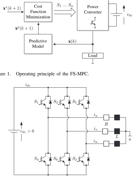
The basic structure of the FS-MPC strategy can be summa-rized as shown in Fig. 1, where:
• n: number of valid switching states of the converter.
• x(k) : variables used in the model to calculate the predictions for each one of thenpossible valid switching states of the converter.
• xp(k+ 1): nprediction variables. • x∗(k+ 1): reference variables.
In order to explain the basic structure and operating prin-ciple of FS-MPC the predictive current control strategy is considered for a well know two-level voltage source inverter (2L-VSI), but this explanation could be easily extended to other topologies.
The predictive current control strategy is performed by:
Predictive Model
Cost Function Minimization
Power Converter
S1... Sn
Load
x∗(k+ 1)
xp(k+ 1)
x(k)
[image:3.612.61.278.55.342.2]vdc
Figure 1. Operating principle of the FS-MPC.
n
S1 S3 S5
S4 S6 S2
R
L iu
iv
iw
vdc>0
[image:3.612.357.516.58.189.2]idc
Figure 2. Three-phase voltage source inverter.
2) Predicting the behaviour of the load currents for each valid switching state of the converter (xp(k+ 1)= ip(k+ 1)).
3) Evaluating the cost functiong for each prediction. 4) Selecting the switching state that minimizes the cost
functiongmin.
5) Applying the new switching state to the converter during the next periodk+ 1.
In order to predict the load current a mathematical model of the converter and load is necessary. The basic structure of the 2L-VSI is shown in Fig. 2. Each leg contains two switches that connect the load to either the positive or negative line. As an operating constrain, only one switch on each leg must be conducting in order to avoid a short-circuit of the dc-link and to avoid interrupt the load current due to the inductive characteristic of the load. Thus, only two possible switching states are valid in each leg. Since this is a three-phase converter, a total of eight valid switching states can be applied, these are summarized in Table I.
It can be deduced from Fig. 2 that the output voltages are synthesized as a function of the inverter switching states and dc-link voltage:
v=
vu
vv
vw
=
S1−S4 S3−S6 S5−S2
vdc (1)
If a passiveR−Lload is considered, the following relation can be formed:
v = Ld
dti + Ri ⇒ d dti =
v−Ri
L (2)
Table I
VALID SWITCHING STATES ON THE2L-VSI. State S1 S2 S3 S4 S5 S6
1 1 1 0 0 0 1
2 1 1 1 0 0 0
3 0 1 1 1 0 0
4 0 0 1 1 1 0
5 0 0 0 1 1 1
6 1 0 0 0 1 1
7 1 0 1 0 1 0
8 0 1 0 1 0 1
where i = [iu iv iw]T. A discrete model is necessary to perform the calculation and implementation of the predictive controller in a digital processor. By approximating the deriva-tive dtdiby:
d dti ≈
i(k+ 1)−i(k)
Ts
(3)
and replacing this in eq.(2), the following discrete form of the load current equation, is obtained:
i(k+ 1) = Ts
Lv(k) +
1 − RTs
L
i(k) (4)
where i(k) correspond to the measurement of i at instant k andv(k) is given as a function of the valid switching states and the measurement ofvdc at instantk, based on eq.(1).
The prediction of i(k+ 1) is compared with a predefined referencei∗(k+ 1)in a cost function, defined as:
g(k+ 1) = |i∗(k+ 1)−i(k+ 1)| (5)
i∗(k+1)can be extrapolated by using the present and previous
values of the current reference as:
i∗(k+ 1) = 3i∗(k) − 3i∗(k−1) + i∗(k−2) (6)
IfTsis sufficient small, then for simplicity it can be assumed
thati∗(k+ 1) ≈ i∗(k). The switching state that minimizes g(k+ 1) is selected and applied to the converter during the next sampling time and this procedure is repeated at every sampling time.
As the main objective of this section is provide to the reader a general overview of the operating principle of FS-MPC, there are some issues that have not been considered in this paper but have already discussed in [26]. Among them the most critical issues that must be taken into consideration are uncertainties in the prediction model, mainly due to parameters variations under different operation conditions and also measurement errors, other discretization methods instance Euler approximations, horizon predictions longer than one and the cost function to be considered (quadratic, square, absolute error, etc.).
III. FOUR-LEGINDIRECTMATRIXCONVERTER (4LEG-IMC)
vs
is
vi
ii
n Rf
Lf
Cf
G
iA
iB
iC
Sr1 Sr3 Sr5
Sr4 Sr6 Sr2
Si1 Si3 Si5 Si7
Si4 Si6 Si2 Si8
vdc>0
idc
i
in
R
[image:4.612.97.519.53.205.2]L v
Figure 3. Circuit topology of a four-leg indirect matrix converter.
inverter with unidirectional switches. Both stages are linked by a dc-link without any storage element; its weight and size are thus reduced and the reliability of the system is improved when compared to conventional topologies. A filter is required at the input side in order to protect the converter from over-voltages as well as to mitigate the harmonic content in the input current due to the commutation of the switches.
From Fig. 3 is possible to identify the relation between input and output variables of the converter in order to define its mathematical model. The dc-link voltage vdc is given as a
function of the the input voltage vi= [vA vB vC]T, and the
instantaneous input transfer matrix as:
vdc=Trvi (7)
with
Tr= [Sr1−Sr4 Sr3−Sr6 Sr5−Sr2] (8)
Similarly, the input currents ii= [iA iB iC]T can be
synthe-sized as a function of the dc-link currentidcand the transpose
of the matrix Tr:
ii=TrTidc (9)
The dc-link current idcis defined as a function of the output
current vector i= [iu iv iw]T and the instantaneous transfer
matrix of the inversion stage:
idc=Tii (10)
with
Ti = Si1−Si7 Si3−Si7 Si5−Si7 (11)
The output three-phase voltage v = [vu vv vw]T can be
synthesized as a function of the dc-link voltage vdc and the
transpose of the matrixTi:
v=TT
i vdc (12)
The neutral current in circulating through the fourth-leg is
given by:
in=iu+iv+iw (13)
As mentioned above, a filter is used on the input side in order to avoid over-voltages and mitigate the harmonic distortion
caused by the commutations. This filter has a second order model defined as:
Lf
dis
dt =vs−vi−Rfis (14)
Cf
dvi
dt =is−ii (15)
where Lf is the inductance, Rf the resistor and Cf the
capacitor of the input filter.
On the output side, and assuming a resistive-inductive load, the following equation describes the behavior of the load:
Ldi
dt =v−Ri (16)
withRandL being the load resistor and inductance, respec-tively. Table II and Table III summarize the respective switch-ing states of the 4Leg-IMC, which are valid for the formulation of the mathematical model of the converter and they must be taken into consideration by the predictive algorithm.
These tables correspond to the nine and sixteen valid switch-ing states for the rectifier and the inverter stages, respectively. By considering the constraints of no short circuits at the input and no open lines in the output, there are one-hundred forty-four possible switches combinations for the 4Leg-IMC. Another operational condition for this converter is that the dc-link voltage must always be positive vdc > 0. As indicated
Table II
VALID SWITCHING STATES ON THE RECTIFIER STAGE. State Sr1 Sr2 Sr3 Sr4 Sr5 Sr6
1 1 1 0 0 0 0
2 0 1 1 0 0 0
3 0 0 1 1 0 0
4 0 0 0 1 1 0
5 0 0 0 0 1 1
6 1 0 0 0 0 1
7 1 0 0 1 0 0
8 0 0 1 0 0 1
9 0 1 0 0 1 0
Table III
VALID SWITCHING STATES ON THE INVERTER STAGE.
State Si1 Si2 Si3 Si4 Si5 Si6 Si7 Si8
1 1 1 0 0 0 1 0 1
2 0 1 1 1 0 0 0 1
3 0 0 0 1 1 1 0 1
4 1 1 1 0 0 0 0 1
5 1 0 0 0 1 1 0 1
6 0 0 1 1 1 0 0 1
7 1 0 1 0 1 0 0 1
8 0 1 0 1 0 1 0 1
9 1 1 0 0 0 1 1 0
10 0 1 1 1 0 0 1 0
11 0 0 0 1 1 1 1 0
12 1 1 1 0 0 0 1 0
13 1 0 0 0 1 1 1 0
14 0 0 1 1 1 0 1 0
15 1 0 1 0 1 0 1 0
16 0 1 0 1 0 1 0 1
The zero dc-link current commutation therefore allows a dead-time commutation of two bidirectional switches on the input side during the period of time while the inverter stage is in a freewheel state. At first sight the main advantage of this commutation technique is the reduction in the switching losses of the input stage which would be negligible as it can be arranged to commutate at zero current.
IV. PROPOSED PREDICTIVE CURRENT CONTROL STRATEGY
FOR THE4LEG-IMC
A. Control scheme
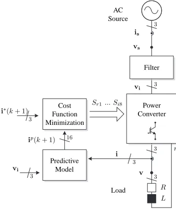
The control strategy validated experimentally in this paper is shown in Fig. 4. The aim of this method is to determine the optimum switching state of the converter, which generates the least amount of tracking error with respect to the load reference, and to apply this state at the next commutation. Further, the control strategy must also assume a positive voltage in the dc-link. To comply with both of these objectives, the control strategy is broken down into the following steps:
1) The reference of the output current is defined asi∗(k+1). The input voltagevi(k)is measured and also the output
currenti(k).
2) These measurements and the model of the system are used to estimatev(k+ 1); then,vp
dc(k+ 1)and the output
currentip(k+ 1)are predicted for the next sample period for each of the valid switching states of 4Leg-IMC.
AC Source
Predictive Model
Filter
Cost Function Minimization
Power Converter
Sr1... Si8
ip(k+ 1)
Load
vs
is
R L
vi
vi
i∗(k+ 1)
i
v
n
3 3
3 3
3 3
3
16
Figure 4. Proposed predictive current control scheme for the 4Leg-IMC.
3) Finally, the predictions are evaluated in a cost function g. The state which generates the least tracking error will be applied during the next sampling time.
B. Prediction model
The discrete nature of power converters and control plat-forms gives rise to the requirement that the system equations be formulated in discrete time. The voltagevdc is defined by
the input voltage at 4Leg-IMCviand the matrix of the rectifier
states Tr. Therefore, the dc-link voltage in the next sample
timek+ 1 is given by the following expression:
vdc(k+ 1) =Tr(k+ 1)vi(k). (17)
The discrete expression of the output currentiis obtained by using the Euler approximation as follows:
i(k+ 1) = Ts Lv(k) +
1−R
LTs
i(k), (18)
whereTs is the sample time, iis the measure of the output
current at instant k, and v is the estimation of the output voltage at time instantk, which is obtained as a function of the valid switching states of the converter.
C. Cost function definition
The cost function determines the tracking error that would be generated by each of the predictions with respect to the reference given for the next sample timek+ 1. The switching state which generates the least tracking error in the cost function is selected and applied during the sample timek+ 1. There are multiple ways to define tracking error. In this paper, the quadratic error will be used, as show in the equation (19):
△i(k+ 1) =(i∗
u(k+ 1)−iu(k+ 1))2+ (i∗
v(k+ 1)−iv(k+ 1))
2 + (i∗
w(k+ 1)−iw(k+ 1))
2 .
Further, the cost function must guarantee that a positive voltage is applied in the dc-link. This condition could be added to the cost function, but this would greatly increase the calculations required. For that reason, it is preferable to select the state of the rectifier beforehand as follows: the rectifier has six valid switching states of which only three are positive at any given time; it is therefore possible to immediately eliminate those which are not. Then, the three positive switching states are compared, and the greatest of the three is selected. Thus, the switching state that generates the greatest voltage in the dc-link will be applied. With the maximum voltage in the dc-link guaranteed, the cost function g will only evaluate the tracking error of the output current. The cost function can therefore be expressed by the following equation:
g(k+ 1) =△i(k+ 1). (20)
V. SIMULATION RESULTS
In this section, the predictive current control method is validated using Matlab-Simulink and the parameters given in Appendix-Table V. Steady-state tests are carried out, and the dynamic behavior of the control strategy is studied. The current references are given as:
i∗
u(k+ 1) =Iusin(2πf Ts),
i∗
v(k+ 1) =Ivsin(2πf Ts−2π/3),
i∗
w(k+ 1) =Iwsin(2πf Ts+ 2π/3),
(21)
where Iu, Iv and Iw, correspond to the amplitudes of phase
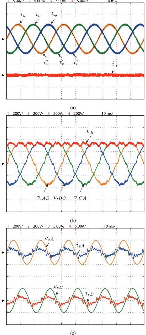
u,v andw, respectively andf is the output frequency. In Fig. 5 is shown the behavior of the 4Leg-IMC while operating with balanced output current references given by Iu = Iv = Iw = 6[A], and an output frequency of f = 30[Hz]. Fig. 5(a) shows the output currentsi, output current referencesi∗, and the neutral currentin. Good behavior of the output currents is observed as they track their respective refer-ences. As expected, since the reference currents are balanced, the neutral current is zero with only high order harmonics due to the commutations. As shown in Fig. 5(b), maximum dc-link voltage is obtained the entire time, independent of the load current conditions, and this voltage presents a waveform similar to a six-pulse rectification. Due to this condition, the source currentis is given as depicted in Fig. 5(c). The ripple observed in these waveforms is produced by the resonance of the input filter due to the commutations, but this issue is beyond the scope of this paper.
Fig. 6(a) shows the behavior of the 4Leg-IMC operating with unbalanced output current references given asIu=2[A],
Iv = 4[A], and Iw = 6[A], respectively, with an output
frequency of f = 30[Hz]. This is the typical application for three-phase four-wire systems, where the load demand varies during each phase. The controller handles each phase current independently and thus the load currents track to their references with low steady-state error. This proves that the predictive strategy can control each current independently. The neutral-current, which is the sum of the three-phase currents, flows through the fourth leg and presents a sinusoidal waveform because the unbalanced references are given with the same reference frequency.
1 5.00A/ 2 5.00A/ 3 5.00A/ 4 5.00A/ 10 ms/
iu iv iw
i∗
u i∗v i∗w in
◮ ◮
(a)
1 200V/ 2 200V/ 3 200V/ 4 200V/ 10 ms/
viAB viBC viCA
vdc
◮
(b)
1 200V/ 2 200V/ 3 5.00A/ 4 5.00A/ 10 ms/
vsB
isB
vsA
isA
◮ ◮
(c)
Figure 5. Simulation results with balanced references; (a) top: output current referencei∗oandio, bottom: neutral currentin. (b) line-to-line input voltages viand dc-link voltagevdc. (c) top: source voltagevsAand source current
isA, bottom: source voltagevsBand source currentisB.
Fig. 6(b) shows the behavior of the 4Leg-IMC operating with unbalanced current references (Iu = 4[A], Iv = 6[A],
and Iw = 2[A]) during a time window of 30[ms] and a
[image:6.612.321.554.56.589.2]1 5.00A/ 2 5.00A/ 3 5.00A/ 4 5.00A/ 10 ms/
iu
iv
iw
i∗
u
i∗
v i∗
w in
◮ ◮
(a)
1 5.00A/ 2 5.00A/ 3 5.00A/ 4 5.00A/ 10 ms/
iu iv
iw
i∗
u
i∗
v
i∗
w
in
◮ ◮
[image:7.612.61.291.54.409.2](b)
Figure 6. Simulation results with unbalanced references in steady state
(top,f = 30[Hz]) and transient state (bottom,f= 60[Hz]): output current referencei∗
o, output currentioand neutral currentin.
circulates when the step from 0[A] to the different reference values is applied. The results showed fast dynamic response with no overshoot for any of the output currents.
VI. EXPERIMENTALRESULTS
A. Description of the experimental setup
In order to validate and demonstrate the feasibility of the proposed current control method, an experimental prototype designed by University of Nottingham has been used. The converter was built with Semikron SKM75GB123D dual IGBT modules for the rectifier side and a Semikron SK35GD126ET module for the inverter side. The control algorithm has been implemented using a host PC running MATLAB-Simulink 2006asoftware with Real-Time Interface (RTI). The dSPACE DS1103 controller is used to handle the control processes such as load current prediction, load voltage estimation, and cost function minimization. The load currents are measured by LEM LAH 25-NP sensors. Feedback from the sensors is sent to the controller through the DS1103I/O connector. The switching state to be applied in the converter is sent from the dSPACE after t = 19[µs] initialized the interruption to a Nexys3 FPGA, which performs the zero dc-link commutation strategy (in 5[µs], where the dead-times has been defined as
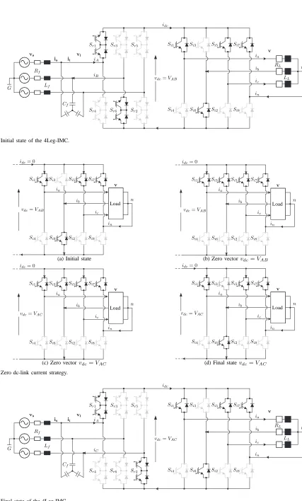
400[ns]) in order to operate the converter safely. The converter requires a commutation sequence that allows a safe change of the rectifier switching state. This problem can be addressed by synchronizing the state changes in the rectifier with the application of a zero voltage space vector in the inverter stage. Under this condition, no current circulates through the dc-link and the rectifier state can be changed without the help of auxiliary commutation circuits [9], [10].
B. Delay compensation
A large number of calculations are required in the predictive algorithm, and this causes a considerable time delay in the actuation. This delay can deteriorate the performance of the system if is not considered in the design of the controller. A solution to compensate for this delay is to calculate the cost function at the end of the next sampling period,g(k+2). Thus, the selected switching state can be applied at instant k+ 1, and therefore one sampling period is available for calculations. To accomplish this, the control scheme is experimentally implemented as follows:
1) Measurement of the load currents.
2) Application of the switching state (calculated in the previous interval).
3) Estimation of current values at time k+ 1, considering the applied switching state.
4) Prediction of the load current for the next sampling instantk+ 2for all possible switching states.
5) Evaluation of the cost function for each prediction. 6) Selection of the switching state that minimizes the cost
function.
C. Zero dc-link current commutation
As previously mentioned, FS-MPC selects the optimal switching state that minimizes the cost functiongand applies it to the converter during the next periodk+ 1. This optimal state is one of the n possible valid switching states of the converter of both the rectifier and inverter stages. In order to ensure a safe commutation of the switches it is necessary a synchronization of both stages. This is accomplished by considering a zero dc-link current commutation strategy which can be synthesized by applying either state 15 or 16 (Table III) of the inverter stage. In other words zero dc-link current is achieved when all the switches related to positive node P (Si1, Si3, Si5, Si7) are closed or when all the switches
related to negative nodeN(Si4,Si6,Si2,Si8) are closed. With
vs
is
vi
ii
n Rf
Lf
Cf
G
iA
iB
Sr1 Sr3 Sr5
Sr4 Sr6 Sr2
Si1 Si3 Si5 Si7
Si4 Si6 Si2 Si8
vdc=VAB
idc
ia
ib
ic
in
RL
LL
[image:8.612.86.513.20.728.2]v
Figure 7. Initial state of the 4Leg-IMC.
n Si1 Si3 Si5 Si7
Si4 Si6 Si2 Si8
vdc=VAB
idc= 0
ia
ib
ic
in
v
Load
(a) Initial state
n Si1 Si3 Si5 Si7
Si4 Si6 Si2 Si8
vdc=VAB
idc= 0
ia
ib
ic
in
v
Load
(b) Zero vectorvdc=VAB
n Si1 Si3 Si5 Si7
Si4 Si6 Si2 Si8
vdc=VAC
idc= 0
ia
ib
ic
in
v
Load
(c) Zero vectorvdc=VAC
n Si1 Si3 Si5 Si7
Si4 Si6 Si2 Si8
vdc=VAC
idc= 0
ia
ib
ic
in
v
Load
[image:8.612.99.517.58.205.2](d) Final statevdc=VAC
Figure 8. Zero dc-link current strategy.
vs
is
vi
ii
n Rf
Lf
Cf
G
iA
iC
Sr1 Sr3 Sr5
Sr4 Sr6 Sr2
Si1 Si3 Si5 Si7
Si4 Si6 Si2 Si8
vdc=VAC
idc
ia
ib
ic
in
RL
LL
v
iu iv iw
in
(a)
vsA
isA
vsB
isB
[image:9.612.317.558.52.379.2](b)
Figure 10. Experimental results with balanced references; (a) top: output
currenti, bottom: neutral currentin(b) top: source voltagevsAand source
currentisA, bottom: source voltagevsBand source currentisB.
After that, the inverter state can change to a new switching state or to keep the initial as depicted in Fig. 8(d).
D. Experimental results in steady and transient states
Fig. 10 and Fig. 11 show the behavior of the 4Leg-IMC operating with the same references considered in simulation section, where nearly the same behavior is observed in each case. Due to channel limitations of our oscilloscopes, it was not possible to measure the dc-link voltage. However, in Fig. 10 it is evident that the performance of the input current is almost the same as the simulation results when maximum dc-link voltage is applied. Fig. 11 shows the behavior of the 4Leg-IMC operating with unbalanced output current references. As previously mentioned, this operating condition is very important because this is the typical application for three-phase four-wire systems. The output current behaves well, with good tracking of its respective references, and it performs almost the same as in the simulation. Again, this experimentally demonstrates that the method can independently control each phase current.
In order to observe the dynamic behavior of the proposed method and compare it with the simulation results, Fig. 11(b) shows the behavior of the 4Leg-IMC operating with unbalanced current references. As expected, a good tracking to their references is observed and due to the unbalanced
iu
iv iw
in
(a)
iv
iu
iw
in
(b)
Figure 11. Experimental results with unbalanced references in steady state
((a),f = 30[Hz]) and transient state ((b),f = 60[Hz]): output current i, neutral currentin.
load current references, a neutral current in is circulating in
the time window. Fast dynamic response is obtained with no overshoot for all the output currents, obtaining almost the same waveforms as those exhibited in the simulation results.
In order to assess the performance of the proposed control scheme, the percentage mean absolute current reference track-ing error %eix and THD percentage parameters, which have
been defined in [47], are used. Table IV shows the performance analysis of the proposed control method at different points of operation, and it compares the simulations to the experimental results. In all cases, the error is below 3[%].
Note that compared to the simulations, this result is slightly higher in the experimental results. Case-2presents the greatest errors, obtaining an average error of 2.68[%]. The calculation of THD is less than 6[%] in the experimental and simu-lation results, except in cases where unbalanced references are applied; there, the phases of smaller amplitude have greater THD. The cases with higher THD are those with a reference amplitude of 2[A], with the maximum in case-4. As expected the performance evaluation corroborates the good behavior of the proposed strategy in experimental and simulated implementations for a wide range of frequencies.
VII. DISCUSSION
[image:9.612.56.298.54.380.2]Table IV
SUMMARY OF STEADY-STATE ANALYSIS FOR SIMULATION AND EXPERIMENTAL RESULTS.
Case Phase Frequency [Hz] Amplitude [A] Simulation Experimental
[%]THD [%]ei [%]THD [%]ei
Case-1 u
30
6 4.4074 1.5979 5.4879 2.1443
v 6 5.6831 1.6493 5.2848 2.2013
w 6 5.6569 1.6551 5.4568 2.2257
avg 5.2491 1.6341 5.4099 2.1907
Case-2 u
60
6 4.3790 1.6156 5.4168 2.7133
v 6 5.6210 1.6434 5.3082 2.6312
w 6 5.7396 1.7598 5.2876 2.6805
avg 5.2465 1.6730 5.3375 2.6805
Case-3 u
30
2 13.6633 1.6101 16.6992 1.8828
v 4 7.5341 1.6193 7.9202 1.9596
w 6 5.4164 1.6179 5.4012 2.1257
avg 8.8713 1.6158 10.0069 1.9894
Case-4 u
60
2 12.7347 1.5143 17.3034 2.0548
v 4 7.6324 1.6263 7.6937 2.1270
w 6 5.4099 1.6961 5.2254 2.5816
avg 8.5923 1.6122 10.0742 2.2545
Case-5 u
30
6 3.1194 1.1392 5.3964 2.4126
v 0 ∼0 ∼0 ∼0 ∼0
w 4 5.5228 1.1437 7.8876 2.1858
avg 2.8807 0.761 4.428 1.9876
Case-6 u
60
6 3.1301 1.2135 5.3724 1.9196
v 0 ∼0 ∼0 ∼0 ∼0
w 4 5.5360 1.1953 7.8014 1.8945
avg 2.8887 0.8029 4.3912 1.0079
of all of them. However, when these control objectives are of a different nature, the combination of them in the cost function is not easy to implement and requires some weighting factors in order to prioritize between one control objective and another. This is still an open issue for research because there are no analytical or numerical procedures to adjust these parameters, they are determined using empirical methods. [26], [48] introduce different types of cost functions as well as procedures to select and adjust the optimal weighting factors depending on the application and type of cost function. An alternative implementation that does not requires weighting factors has been recently presented in [49].
One disadvantage when experimental implementations of FS-MPC are undertaken is the large computation requirement to evaluate the predictions related to each valid switching state of the converter. This computational demand increases for a converter (such as the 4Leg-IMC) with a large number of valid commutation states. Despite the new advances in more powerful and faster processors [31], this computation time introduces a considerable time delay which can deteriorate the performance of the system if not considered in the design of the controller. As reported in [26], [50], not only does the computation time introduce this delay but also this delay can appear due to the need for future values of the references in the cost function, specially ifTsis not sufficient small. As
previ-ously discussed, this issue has been taken into consideration by predicting the variables for k= 2 instead k= 1, because the real effect of apply the selected switching state is only reflected after the next sampling time. The main purpose of this paper has been to describe the experimental validation of a simple control strategy for the four-leg indirect matrix converter. As demonstrated by simulation and experimental results, this simple control strategy generates a very good load current
with almost sinusoidal waveform. The consequence of this technique is the square waveform of the input current, which is similar to a classical diode rectifier with large inductance at the load. In some applications, the users can operate with this low quality current as shown in [2], where the harmonics can be cancelled by an array of converters interconnected by a multi-winding transformer. As reported in [2], some applications that can be found are: wind turbine generator systems, external elevators, skin-pass mills, among others. The control of the input side implies a more complex prediction model and control algorithm, with an additional prediction model, more measurements and computation time, obtaining an improved behavior of the input current such as depicted in Fig. 12. As observed, by including a new term in the cost function, it is possible to obtain current in phase with its respective source voltage, but then new issues appear such as the resonance of the input filter (specially with uncertainties in the filter model, measurements errors and with a not optimized input filter) as well as the selection of adequate weighting factors in the cost function. This issue is not in the scope of this paper.
VIII. CONCLUSION
In this paper the experimental validation of a predictive cur-rent control strategy for a four-leg indirect matrix converter has been presented which represents a very attractive alternative for power electronics applications.
iu iv iw
in
(a)
vsA
isA
vsB
isB
(b)
Figure 12. Experimental results with minimization of the instantaneous input reactive power; (a)f= 60[Hz] top: output currenti, bottom: neutral current
in(b) top: source voltagevsAandisA, bottom: source voltagevsBandisB.
reference tracking error%eixand THD percentage parameters
which have been shown to be acceptable for these applications. Future research considers the assessment with classical mod-ulation and control techniques and other issues such as the study under uncertain in the parameters, and improvement of the input current behaviour.
APPENDIX
Simulation and experimental parameters are presented in Table V.
Table V
SIMULATION AND EXPERIMENTAL PARAMETERS
Variables Description Value
Ts Sampling time 30 [µs]
Vs Supply phase voltage 200 [Vph]
fs Supply frequency 50 [Hz]
Lf Input filter inductance 3 [mH]
Cf Input filter capacitance 15 [µF]
Rf Input filter resistance 1 [Ω]
RL Load resistance 10 [Ω]
LL Load inductance 15 [mH]
ACKNOWLEDGMENTS
The authors wish to thank the financial support from CONI-CYT Initiation into Research 11121492 Project, and the finan-cial support of CONICYT/FONDAP/15110019. Furthermore,
the work of C. F. Garc´ıa was supported by CONICYT Schol-arships for PhD studies in Chile and Programa de Iniciaci´on a la Investigaci´on Cient´ıfica (PIIC) financed by Universidad T´ecnica Federico Santa Mar´ıa.
REFERENCES
[1] J. Kolar and T. Friedli, “Milestones in matrix converters research,” Industry Applications, IEEJ Journal on, vol. 1, no. 1, pp. 2–14, 2012. [2] E. Yamamoto, H. Hara, T. Uchino, M. Kawaji, T. Kume, J.-K. Kang,
and H.-P. Krug, “Development of mcs and its applications in industry [industry forum],” Industrial Electronics Magazine, IEEE, vol. 5, no. 1, pp. 4–12, 2011.
[3] L. Empringham, J. Kolar, J. Rodriguez, P. Wheeler, and J. Clare, “Technological issues and industrial application of matrix converters: A review,” Industrial Electronics, IEEE Transactions on, vol. 60, no. 10, pp. 4260–4271, Oct 2013.
[4] P. Wheeler, J. Rodriguez, J. Clare, L. Empringham, and A. Weinstein, “Matrix converters: a technology review,” Industrial Electronics, IEEE Transactions on, vol. 49, no. 2, pp. 276–288, Apr 2002.
[5] J. Kolar, T. Friedli, F. Krismer, and S. Round, “The essence of three-phase ac/ac converter systems,” in Power Electronics and Motion Control Conference, 2008. EPE-PEMC 2008. 13th, Sept 2008, pp. 27–42. [6] J. Kolar, T. Friedli, J. Rodriguez, and P. Wheeler, “Review of
three-phase pwm ac-ac converter topologies,” Industrial Electronics, IEEE Transactions on, vol. 58, no. 11, pp. 4988–5006, Nov 2011.
[7] P. Zanchetta, P. Wheeler, J. Clare, M. Bland, L. Empringham, and D. Katsis, “Control design of a three-phase matrix-converter-based ac-ac mobile utility power supply,” Industrial Electronics, IEEE Transactions on, vol. 55, no. 1, pp. 209–217, Jan 2008.
[8] S. Lopez Arevalo, P. Zanchetta, P. Wheeler, A. Trentin, and L. Em-pringham, “Control and implementation of a matrix-converter-based ac ground power-supply unit for aircraft servicing,” Industrial Electronics, IEEE Transactions on, vol. 57, no. 6, pp. 2076–2084, June 2010. [9] J. Kolar, F. Schafmeister, S. Round, and H. Ertl, “Novel three-phase
ac-ac sparse matrix converters,” Power Electronics, IEEE Transactions on, vol. 22, no. 5, pp. 1649–1661, Sept 2007.
[10] T. Nguyen and H.-H. Lee, “Dual three-phase indirect matrix converter with carrier-based pwm method,” Power Electronics, IEEE Transactions on, vol. 29, no. 2, pp. 569–581, Feb 2014.
[11] H.-L. Jou, K.-D. Wu, J.-C. Wu, and W.-J. Chiang, “A three-phase four-wire power filter comprising a three-phase three-four-wire active power filter and a zig-zag transformer,” Power Electronics, IEEE Transactions on, vol. 23, no. 1, pp. 252–259, Jan 2008.
[12] B. Singh, P. Jayaprakash, S. Kumar, and D. Kothari, “Implementation of neural-network-controlled leg vsc and a transformer as three-phase four-wire dstatcom,” Industry Applications, IEEE Transactions on, vol. 47, no. 4, pp. 1892–1901, July 2011.
[13] A. Negi, S. Surendhar, S. Kumar, and P. Raja, “Assessment and compar-ison of different neutral current compensation techniques in three-phase four-wire distribution system,” in Power Electronics for Distributed Generation Systems (PEDG), 2012 3rd IEEE International Symposium on, June 2012, pp. 423–430.
[14] N.-Y. Dai, M.-C. Wong, F. Ng, and Y.-D. Han, “A fpga-based generalized pulse width modulator for three-leg center-split and four-leg voltage source inverters,” Power Electronics, IEEE Transactions on, vol. 23, no. 3, pp. 1472–1484, May 2008.
[15] P. Wheeler, P. Zanchetta, J. Clare, L. Empringham, M. Bland, and D. Katsis, “A utility power supply based on a four-output leg matrix converter,” Industry Applications, IEEE Transactions on, vol. 44, no. 1, pp. 174–186, Jan 2008.
[16] R. Cardenas, C. Juri, R. Pena, J. Clare, and P. Wheeler, “Analysis and experimental validation of control systems for four-leg matrix converter applications,” Industrial Electronics, IEEE Transactions on, vol. 59, no. 1, pp. 141–153, Jan 2012.
[17] S. Kwak, “Four-leg-based fault-tolerant matrix converter schemes based on switching function and space vector methods,” Industrial Electronics, IEEE Transactions on, vol. 59, no. 1, pp. 235–243, Jan 2012. [18] R. Cardenas, C. Juri, R. Pena, P. Wheeler, and J. Clare, “The application
of resonant controllers to four-leg matrix converters feeding unbalanced or nonlinear loads,” Power Electronics, IEEE Transactions on, vol. 27, no. 3, pp. 1120–1129, March 2012.
[image:11.612.57.297.53.379.2][20] Y. Sun, M. Su, X. Li, H. Wang, and W. Gui, “Indirect four-leg matrix converter based on robust adaptive back-stepping control,” Industrial Electronics, IEEE Transactions on, vol. 58, no. 9, pp. 4288–4298, Sept 2011.
[21] K. Kobravi, R. Iravani, and H. Kojori, “Three-leg/four-leg matrix converter generalized modulation strategy-part i: A new formulation,” Industrial Electronics, IEEE Transactions on, vol. 60, no. 3, pp. 848– 859, March 2013.
[22] ——, “Three-leg/four-leg matrix converter generalized modulation strategy-part ii: Implementation and verification,” Industrial Electronics, IEEE Transactions on, vol. 60, no. 3, pp. 860–872, March 2013. [23] J. Holtz and S. Stadtfeld, “A predictive controller for the stator current
vector of ac machines fed from a switched voltage source,” March 1983, pp. 1665–1675.
[24] S. Kouro, P. Cortes, R. Vargas, U. Ammann, and J. Rodriguez, “Model predictive control-A simple and powerful method to control power converters,” IEEE Trans. Ind. Electron., vol. 56, no. 6, pp. 1826–1838, Jun. 2009.
[25] P. Cortes, M. Kazmierkowski, R. Kennel, D. Quevedo, and J. Rodriguez, “Predictive control in power electronics and drives,” IEEE Trans. Ind. Electron., vol. 55, no. 12, pp. 4312–4324, Dec. 2008.
[26] J. Rodriguez and P. Cortes, Predictive Control of Power Converters and Electrical Drives, 1st ed. Chichester, UK: IEEE Wiley press, Mar. 2012.
[27] C. Buccella, C. Cecati, and H. Latafat, “Digital control of power converters - a survey,” Industrial Informatics, IEEE Transactions on, vol. 8, no. 3, pp. 437–447, Aug 2012.
[28] W.-M. Lin, C.-M. Hong, and C.-H. Chen, “Neural-network-based mppt control of a stand-alone hybrid power generation system,” Power Electronics, IEEE Transactions on, vol. 26, no. 12, pp. 3571–3581, Dec 2011.
[29] R.-J. Wai and L.-C. Shih, “Adaptive fuzzy-neural-network design for voltage tracking control of a dc-dc boost converter,” Power Electronics, IEEE Transactions on, vol. 27, no. 4, pp. 2104–2115, April 2012. [30] F. Villarroel, J. Espinoza, C. Rojas, J. Rodriguez, M. Rivera, and
D. Sbarbaro, “Multiobjective switching state selector for finite-states model predictive control based on fuzzy decision making in a matrix converter,” Industrial Electronics, IEEE Transactions on, vol. 60, no. 2, pp. 589–599, Feb 2013.
[31] J. Rodriguez, M. Kazmierkowski, J. Espinoza, P. Zanchetta, H. Abu-Rub, H. Young, and C. Rojas, “State of the art of finite control set model predictive control in power electronics,” Industrial Informatics, IEEE Transactions on, vol. 9, no. 2, pp. 1003–1016, May 2013. [32] P. Correa, J. Rodriguez, M. Rivera, J. Espinoza, and J. Kolar, “Predictive
control of an indirect matrix converter,” Industrial Electronics, IEEE Transactions on, vol. 56, no. 6, pp. 1847–1853, June 2009.
[33] M. Rivera, J. Rodriguez, J. Espinoza, and H. Abu-Rub, “Instantaneous reactive power minimization and current control for an indirect matrix converter under a distorted ac supply,” Industrial Informatics, IEEE Transactions on, vol. 8, no. 3, pp. 482–490, Aug 2012.
[34] M. Rivera, C. Rojas, J. Rodriguez, P. Wheeler, B. Wu, and J. Espinoza, “Predictive current control with input filter resonance mitigation for a direct matrix converter,” Power Electronics, IEEE Transactions on, vol. 26, no. 10, pp. 2794–2803, Oct 2011.
[35] M. Rivera, J. Rodriguez, B. Wu, J. Espinoza, and C. Rojas, “Current control for an indirect matrix converter with filter resonance mitigation,” Industrial Electronics, IEEE Transactions on, vol. 59, no. 1, pp. 71–79, Jan 2012.
[36] M. Rivera, J. Rodriguez, P. Wheeler, C. Rojas, A. Wilson, and J. Es-pinoza, “Control of a matrix converter with imposed sinusoidal source currents,” Industrial Electronics, IEEE Transactions on, vol. 59, no. 4, pp. 1939–1949, April 2012.
[37] M. Rivera, J. Rodriguez, J. Espinoza, T. Friedli, J. Kolar, A. Wilson, and C. Rojas, “Imposed sinusoidal source and load currents for an indirect matrix converter,” Industrial Electronics, IEEE Transactions on, vol. 59, no. 9, pp. 3427–3435, Sept 2012.
[38] M. Rivera, C. Rojas, J. Rodriguez, and J. Espinoza, “Methods of source current reference generation for predictive control in a direct matrix converter,” Power Electronics, IET, vol. 6, no. 5, pp. 894–901, May 2013.
[39] M. Rivera, A. Wilson, C. Rojas, J. Rodriguez, J. Espinoza, P. Wheeler, and L. Empringham, “A comparative assessment of model predictive current control and space vector modulation in a direct matrix converter,” Industrial Electronics, IEEE Transactions on, vol. 60, no. 2, pp. 578– 588, Feb 2013.
[40] R. Vargas, U. Ammann, B. Hudoffsky, J. Rodriguez, and P. Wheeler, “Predictive torque control of an induction machine fed by a matrix
converter with reactive input power control,” Power Electronics, IEEE Transactions on, vol. 25, no. 6, pp. 1426–1438, June 2010.
[41] R. Vargas, J. Rodriguez, C. Rojas, and M. Rivera, “Predictive control of an induction machine fed by a matrix converter with increased efficiency and reduced common-mode voltage,” Energy Conversion, IEEE Transactions on, vol. PP, no. 99, pp. 1–13, 2014.
[42] R. Vargas, U. Ammann, and J. Rodriguez, “Predictive approach to increase efficiency and reduce switching losses on matrix converters,” Power Electronics, IEEE Transactions on, vol. 24, no. 4, pp. 894–902, April 2009.
[43] M. Rivera, I. Contreras, J. Rodriguez, R. Pena, and P. Wheeler, “A simple current control method with instantaneous reactive power mini-mization for four-leg indirect matrix converters,” in Power Electronics and Applications (EPE 2011), Proceedings of the 2011-14th European Conference on, Aug 2011, pp. 1–9.
[44] C. Garcia, M. Rivera, M. Lopez, J. Rodriguez, P. Wheeler, R. Pena, J. Espinoza, and J. Riedemann, “Predictive current control of a four-leg indirect matrix converter with imposed source currents and common-mode voltage reduction,” in Energy Conversion Congress and Exposition (ECCE), 2013 IEEE, Sept 2013, pp. 5306–5311.
[45] M. Rivera, J. Rodriguez, C. Garcia, R. Pena, and J. Espinoza, “A simple predictive voltage control method with unity displacement power factor for four-leg indirect matrix converters,” in Power Electronics and Motion Control Conference (EPE/PEMC), 2012 15th International, 2012, pp. DS2c.5–1–DS2c.5–6.
[46] P. Cortes, M. Kazmierkowski, R. Kennel, D. Quevedo, and J. Ro-driguez, “Predictive control in power electronics and drives,” Industrial Electronics, IEEE Transactions on, vol. 55, no. 12, pp. 4312–4324, Dec 2008.
[47] V. Yaramasu, M. Rivera, B. Wu, and J. Rodriguez, “Model predictive current control of two-level four-leg inverters - part i: Concept, algo-rithm, and simulation analysis,” Power Electronics, IEEE Transactions on, vol. 28, no. 7, pp. 3459–3468, 2013.
[48] P. Cortes, S. Kouro, B. La Rocca, R. Vargas, J. Rodriguez, J. Leon, S. Vazquez, and L. Franquelo, “Guidelines for weighting factors design in model predictive control of power converters and drives,” in Industrial Technology, 2009. ICIT 2009. IEEE International Conference on, Feb 2009, pp. 1–7.
[49] C. Rojas, J. Rodriguez, F. Villarroel, J. Espinoza, C. Silva, and M. Trin-cado, “Predictive torque and flux control without weighting factors,” Industrial Electronics, IEEE Transactions on, vol. 60, no. 2, pp. 681– 690, Feb 2013.
[50] P. Cortes, J. Rodriguez, C. Silva, and A. Flores, “Delay compensation in model predictive current control of a three-phase inverter,” Industrial Electronics, IEEE Transactions on, vol. 59, no. 2, pp. 1323–1325, Feb 2012.
Crisiti´an Garc´ıa (M13) received the B.S. and
M.S. degrees in electronics engineering from
the Universidad T´ecnica Federico Santa Mar´ıa (UTFSM),Valpara´ıso, Chile, in 2013. His research interests include matrix converters and model pre-dictive control of power converters and drives. Mr. Garc´ıa was awarded a scholarship from the Chilean Research Foundation CONICYT in 2013 to pursue his Ph.D. studies in power electronics at Universidad T´ecnica Federico Santa Mar´ıa (UTFSM), Valpara´ıso, Chile.
Marco Rivera (S’09-M’11) received his B.Sc. in
Miguel L´opez was born in Vi˜na del Mar, Chile, in
1988. He received his B.Sc. in Electronic Engineer-ing and M.Sc. in Electronic EngineerEngineer-ing from the Universidad Tcnica Federico Santa Mara (UTFSM), Valparaso, Chile, in 2014. His research interests include power electronics converters, renewable en-ergy power conversion systems, motor drives and their applications.
Jos´e Rodriguez (M’81-SM’94-F’10) received the
Engineer degree in electrical engineering from the Universidad T´ecnica Federico Santa Mar´ıa, in Val-para´ıso, Chile, in 1977 and the Dr.-Ing. degree in electrical engineering from the University of Erlan-gen, ErlanErlan-gen, Germany, in 1985. He has been with the Department of Electronics Engineering, Univer-sidad T´ecnica Federico Santa Mar´ıa, since 1977, where he is currently full Professor and Rector. He has coauthored more than 350 journal and con-ference papers. His main research interests include multilevel inverters, new converter topologies, control of power converters, and adjustable-speed drives. Dr. Rodriguez is member of the Chilean Academy of Engineering.
Rub´en Pe ˜na (S’95-M’97) was born in Coronel,
Chile. He received his Electrical Engineering degree from the Universidad de Concepci´on, Chile, in 1984 and his M.Sc. and Ph.D. degrees from the University of Nottingham, U.K., in 1992 and 1996 respectively. From 1985 to 2008 he was a lecturer in the Uni-versidad de Magallanes, Chile. He is currently with the Electrical Engineering Department, Universida de Concepci´on, Chile. His main interests are in control of power electronics converters, A.C. drives and renewable energy systems. Dr. Pe˜na received the Best Paper Award from the IEEE Transactions on Industrial Electronics in 2004, and the Ramon Salas Edward Award for research excellence from the Chilean Institute of Engineers in 2009. Dr. Pe˜na is a member of the Institute of Electrical and Electronic Engineers.
Patrick W. Wheeler (M’00, SM’13) received his
BEng [Hons] degree in 1990 from the University of Bristol, UK. He received his PhD degree in Electri-cal Engineering for his work on Matrix Converters from the University of Bristol, UK in 1994. In 1993 he moved to the University of Nottingham and worked as a research assistant in the Department of Electrical and Electronic Engineering. In 1996 he be-came a Lecturer in the Power Electronics, Machines and Control Group at the University of Nottingham, UK. Since January 2008 he has been a Full Professor
in the same research group. He is an IEEE PELsM emberatLarge and
an IEEE PELs Distinguished Lecturer. He has published over 350 academic publications in leading international conferences and journals.
Jos’e R. Espinoza (S’92-M’97) received the Eng.

![Figure 6.Simulation results with unbalanced references in steady state(top, f = 30[Hz]) and transient state (bottom, f = 60[Hz]): output currentreference i∗o, output current io and neutral current in.](https://thumb-us.123doks.com/thumbv2/123dok_us/8689495.379611/7.612.61.291.54.409/figure-simulation-unbalanced-references-transient-currentreference-current-neutral.webp)
![Figure 11.Experimental results with unbalanced references in steady stateneutral current((a), f = 30[Hz]) and transient state ((b), f = 60[Hz]): output current i, in.](https://thumb-us.123doks.com/thumbv2/123dok_us/8689495.379611/9.612.317.558.52.379/figure-experimental-results-unbalanced-references-stateneutral-current-transient.webp)
![Figure 12.Experimental results with minimization of the instantaneous inputireactive power; (a) f = 60[Hz] top: output current i, bottom: neutral currentn (b) top: source voltage vsA and isA, bottom: source voltage vsB and isB.](https://thumb-us.123doks.com/thumbv2/123dok_us/8689495.379611/11.612.57.297.53.379/figure-experimental-minimization-instantaneous-inputireactive-current-currentn-voltage.webp)
