A new 2D image compression technique for 3D surface
reconstruction
SIDDEQ, M.M. and RODRIGUES, Marcos
<http://orcid.org/0000-0002-6083-1303>
Available from Sheffield Hallam University Research Archive (SHURA) at:
http://shura.shu.ac.uk/8334/
This document is the author deposited version. You are advised to consult the
publisher's version if you wish to cite from it.
Published version
SIDDEQ, M.M. and RODRIGUES, Marcos (2014). A new 2D image compression
technique for 3D surface reconstruction. In: MASTORAKIS, Nikos, PSARRIS,
Kleanthis, VACHTSEVANOS, George, DONDON, Philippe, MLADENOV, Valeri,
BULUCEA, Aida, RUDA, Imre and MARTIN, Olga, (eds.) Advances in information
sciences and applications : Proceedings of 18th International Conference on
Computers (part of CSCC'14). Recent advances in computer engineering series, 1
(22). World Scientific and Engineering Academy and Society (WSEAS), 379-386.
Copyright and re-use policy
See
http://shura.shu.ac.uk/information.html
Sheffield Hallam University Research Archive
Abstract— Image compression is one of the important techniques used today for image and video transmission. There are many types of image compression techniques are used these days; one of them is JPEG technique. In this research, we introduce a new idea for applying the JPEG technique with Discrete Wavelet Transform (DWT) for high-resolution images. Our image compression algorithm consists of; firstly, transform an image by single level DWT. Secondly, JPEG algorithm applied on "LL" sub-band this process is called JPEG Transformation. Thirdly, separate the final transformed matrix into DC-Array and AC-Matrix contains DC values and AC coefficients respectively. Finally, the minimize-matrix-size algorithm applied on AC-Matrix followed by arithmetic coding. The novel decompression algorithm used in this research is Parallel Sequential Search Algorithm, which is represented inverse minimize-matrix-size algorithm. The searching algorithm consist of a P pointers, all these pointers are working in parallel to find the original AC-coefficients. Thereafter, combines all decoded DC-values with the decoded AC-coefficients in one matrix followed by apply inverse JPEG transformed and inverse DWT. the technique is tested by compression and reconstruction of 3D surface patches. Additionally, this technique is compared with JPEG and JPEG2000 algorithm by using 2D and 3D RMSE.
Keywords—DWT, JPEG, Minimize-Matrix-Size Algorithm, Parallel SS-Algorithm, 3D reconstruction
I. INTRODUCTION
ompression methods are being rapidly developed to compress large data files such as images, where data compression in multimedia applications has lately become more vital. With the increasing growth of technology and the entrance into the digital age, a vast amount of image data must be stored in a proper way using efficient methods usually succeed in compressing images, while retaining high image quality and marginal reduction in image size. Since first attempts, the discrete cosine transform (DCT) domain has been used [1]. Image is divided into segments and each segment is then a subject of the transform, creating a series of frequency components that correspond with detail levels of the image.
M. M. Siddeq, M. A. Rodrigues, Geometric Modeling and Pattern Recognition Research Group, Sheffield Hallam University, Sheffield, UK e-mail: [email protected] , [email protected]
Several forms of coding are applied in order to store only coefficients that are found as significant. Such a way is used in
the popular JPEG file format, and most video compression methods and multi-media applications are generally based on it [2][4].
A step beyond JPEG is the JPEG2000 that is based on wavelet transform which is one of the mathematical tools for hierarchically decomposing functions. Image compression using Wavelet Transforms is a powerful method that is preferred by scientists to get the compressed images at higher compression ratios with higher PSNR values [3][5]. Its superiority in achieving high compression ratio, error resilience, and other features promotes it to become the tomorrow's compression standard and leads to the JPEG2000 ISO. As referred to the JPEG abbreviation which stands for Joint Photographic Expert Group, JPEG2000 codec is more efficient than its predecessor JPEG and overcomes its drawbacks [12]. It also offers higher flexibility compared to even many other codec such as region of interest, high dynamic range of intensity values, multi component, lossy and lossless compression, efficient computation, compression rate control, etc. The robustness of JPEG2000 stems from its utilization to the Discrete Wavelet Transform (DWT) in encoding the image data. DWT exhibits high effectiveness in image compression due to its support to multi-resolution representation in both spatial and frequency domains. In addition, DWT supports progressive image transmission and region of interest coding [13][14].
II. PROPOSED 2DIMAGE COMPRESSION ALGORITHM
JPEG technique is one of the greatest techniques are used in the image compression; also it is used for encryption and steganography. The important feature of the JPEG it is uses the "Quality" parameter, which allow for the user to adjust the amount of the data lost over a very wide range. In this section we explain in details about JPEG transformation applied on the discrete wavelet transform. The JPEG transformation consists of; 1) Apply DCT on each 8x8 block followed by quantization process. 2) Zigzag scan used for converting each block into 64 coefficients, and store 64-coefficients in two different matrices [11]. Fig.-1 describes the proposed DWT-JPEG algorithm steps.
A New 2D Image Compression Technique for
3D Surface Reconstruction
M. M. Siddeq, Prof. M. Rodrigues
A. Discrete Wavelet Transform
DWT is the first phase in the proposed image compression algorithm, to produces four sub-bands (See Figure-1). The top-left corner is called "LL", represents low-frequency coefficients, and the top-right called "HL" consists of residual vertical frequencies. The bottom-left corner "LH", and bottom-right corner "HH" are represents; residual horizontal and residual vertical frequencies respectively [5]. Most values in the high-frequency domains (i.e HL, LH and HH) are zeros or insignificant coefficients without affecting on the reconstructed image. For this reason all the high frequency domains are discarded in this research (i.e. set all values to zero), and this does not mean the image will lose much information, this is depends on the image dimensions. DWT uses filters for decomposing image [15], these filters assists to increase the number of zeros in high frequency sub-bands. One of these filters is used in decomposition and composition is called Daubechies Filter. This filter stores much information about the original image in the "LL" sub-band, while other high-frequency domains contain less significant details, and this is one of important property in Daubechies filter. The reconstructed image just need "LL" sub-band, while other high-frequency sub-bands are omitted, and this is the key for achieving a high compression ratio [8][9]. Fig.-2 shows the decomposition image by Daubechies filter, and then recomposes sub-bands without high-frequencies.
B. JPEG Transformation
The "LL" sub-band partitioned into non-overlapped 8x8 blocks, each block is transformed by using two-dimensional DCT to produce de-correlated coefficients. Each 8x8 frequency domain consists of; DC-value at the first location, while other coefficients are called AC coefficients [5]. After applying the two-dimensional DCT on each 8x8 block, each block quantized by the Quantization Matrix "QM" using dot-division-matrix with truncates the results. This process removes insignificant coefficients and increases the number of the zeros in the each block. QM computes as follows:
⎩ ⎨ ⎧ = + + + = + + = even j i QM if j i Block odd j i QM if j i Block j i QM )) , ( ( 1 ) ( )) , ( ( ), ( ) ,
( (1)
Where \ Block: is represented block size i ,j=1,2,3…,Block
In the above Eq. (2), the factor "Scale" it is used to increase/decrease the values of the "QM". Thus, image details is reduced in case of the factor Scale >1. There is no limited range for this factor, because this is depends on the DCT coefficients.
Each quantized 8x8 block is converted into one-dimensional array (i.e. the array contains 64 coefficients) by zigzag scan [13].Whereas, the first value transferred into new array called DC-Array, while others are 63 coefficients are stored to new matrix "LLAC". Finally, the DC-Array is compressed by using Arithmetic coding. The Arithmetic coding is one of the important methods used in data compression method, especially this method used in JPEG2000. Arithmetic coding depends on "Low" and "High" equations to generate streams of bits [5].
III. MINIMIZE-MATRIX-SIZE ALGORITHM
LLAC Matrix ready for coding by Minimize-Matrix-Size Algorithm, this algorithm applied on each three coefficients,
Fig.-1, Proposed DWT-JPEG Compression Technique
to produce single data. This means reduce each three columns to single coded array which is called Minimized-Array. However, the bit size for each data in the Minimized-Array increased. Fig.-4 shows converting three columns into one dimensional array [9][10].
In above figure-4 (a) K1, K2 and K3 represents key for conversion. The following equation illustrates converting three data, to single data.
Di=(K1× Ai)+(K2× Bi) + (K3× Ci) (3)
Where\ i=1, 2, 3,…n
If the key is lost, the data cannot be retrieved, because the keys are used in coding and decoding. The key values generated through random number generator. For example, assume we have the following array: [3 -9 0], Maximum value in the array=|-9|=M= 9, and Base Value=0.1; Key1= 0.8147, Key2=0.9058, and Key3=0.1270. The key generated once for all matrix data, after calculation, all coded data "Di" arranged together to be one-dimensional array (i.e. Minimized-Array).
Before apply the Minimize-Matrix-Size algorithm, the algorithm computes the probability of the data for AC-matrix. These probabilities are called Limited-Data, which is used later in decompression stage [10]. The Limited-Data stored as additional information with compressed data. Fig.-5, describes Limited-Data computed from original matrix.
The Minimized-array contains positive and negative data, and each data size reached to 32-bit, these data can be compress by a coding method, but the index size (i.e. header compressed file) reaches to 50% of compressed data size. The index data are used in decompression stage, therefore, the index data breakup into parts for easy compress. Each data partitioned into parts: 4-bit (i.e. each data in index may be breakup into six 4-bit data), and this process increase the
probability of redundant data, finally, coded by arithmetic coding.
IV. PROPOSED DECOMPRESSION ALGORITHM
The decompression algorithm represents reverse steps for the proposed image compression. Firstly, applied arithmetic decoding for decompress DC-array, Nonzero-array and Zero-array. Thereafter, nonzero-array and zero-array are combined together for reconstructing minimized-array. Secondly, using novel Parallel Sequential Search Algorithm (PSS-Algorithm), moreover, this algorithm represents inverse Minimize-Matrix-Size Algorithm for reconstructing AC-Matrix. PSS-Algorithm, estimates (Ai, Bi and Ci) by using "Di" with Key. Whereas, Ai, Bi and Ci are represents estimated columns for decompress AC-Matrix. PSS-Algorithm can be illustrates in the following steps:
Step 1: PSS-Algorithm starts to pick first P data from the Limited-Data, and then these P data are connected with each other look like a network as shown in Fig.-6.
In Fig.-6 "Column-1" data connected as a network with "Column-2" data, also "Column-2" is networking with "Column-3". In another words, the searching algorithm computes all options in parallel. For example: A=[1 -1 0] , B=[1 -2 0] and C=[3 -1 5], and P=3, according to Eq.(3) "A","B" and "C" computes 27 times. This means, all options computes in parallel and one option will be matched with the "Di", and "Ai", "Bi" and "Ci" in "Column-1", "Column-2" and "Column-3" represented decompressed data.
Initially, PSS algorithm starts with P=10 data from "Limited-Data(1…10.)" that used by the algorithm, these data are estimates three columns (A, B and C), as mentioned in Figure-8(a). Thereafter, the algorithm starts searching for original data (Ai, Bi and Ci) which is depends on compressed column "Di" and Key-values. The first iteration for the algorithm starts with matching selected "Di" with 10 outputs from PSS-algorithm (i.e. P=10, three columns = P3= 1000 data). In another words ,Eq.(3) executed 1000 times in parallel for finding original values for columns (A,B and C) as mentioned in Figure-7(b). If result unmatched, in this case the second option will be taken form "Limited-Data(11…20.)" (i.e. selecting another 10 data from Limited-Data transferred to Array1), while "Array2" and "Array3" are remains in same old options, if the processing still did not find the result, in this case"Array2=Array1" (i.e. transferred data from Array1 to Array2), then new processing starts.
Fig.-4, Minimize-Matrix-Size Algorithm
Through this explanation, "Array1", "Array2" and "Array3" are working like digital clock: sec, min. and hour respectively, this process will continue until finding all original columns (Ai, Bi and Ci) in AC-Matrix.
Step 2: In this step decompressed AC-Matrix composed with each DC-value (i.e. DC-values from DC-array), then followed by zigzag scan to convert each 64-coefficients to 8x8 blocks. These blocks combined with each other to build LL sub-bands. Subsequently, applied inverse quantization (i.e. dot-multiplication), followed by inverse DCT on each 8x8 block. Finally, applied inverse DWT for obtaining 2D image
linked with 3D application for reconstruct 3D image. The decompression algorithm steps are showed in Figure-8.
V. EXPERIMENTS RESULTS
The proposed compression system applied on images, as shown in Figure-9. The tests have been performed using Daubechies DWT (db3), the block sizes used by DCT (4×4 and 8×8). The results described below used Matlab for 2D image compression in connection with a 3D visualization software running on an AMD Quad-Core microprocessor. Tables: 1 and 2 shows the compressed size possibilities for each image.
The proposed decompression algorithm applied on each compressed data, as mentioned before in section 3. The decompressed algorithm shows range of image quality according to "Scale" parameter and blocks size used in and JPEG-Transformation (See Eq.(2)). Figure-10 and Figure-11 shows sequence of decompressed 3D images: Face1 and FACE2 respectively.
Tables: 3 and 4 shows time execution for PSS-algorithm for each image using two types of pointers (P=5 and P=10). The pointer refers to number of coefficients using in parallel for space search (i.e. searching in Limited-Data).
(a)copy P data from Limited-Data to temporary “Array1” for PSS-Algorithm
Table-1, 2D image"FACE1.bmp" compressed by the proposed image compression algorithm
Scale – parameter
used by quantization Block size used by JPEG-Transformation
Compressed size
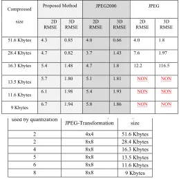
2 4x4 51.6 Kbytes
2 8x8 28.4 Kbytes
4 8x8 16.3 Kbytes
5 8x8 13.5 Kbytes
6 8x8 11.6 Kbytes
8 8x8 9 Kbytes
Table-2, 2D image"FACE2.bmp" compressed by the proposed image compression algorithm
Scale – parameter
used by quantization Block size used by JPEG-Transformation
Compressed size
2 4x4 33 Kbytes
2 8x8 16.8 Kbytes
4 8x8 9.4 Kbytes
5 8x8 7.7 Kbytes
(b) data matched through PSS-Algorithm Fig.-7, (a, b) strategy work for PSS-Algorithm
Table 3, Parallel Search algorithm time execution for image: FACE1.bmp
Parameters PSS-Algorithm, P=5 PSS-Algorithm, P=10
Scale –used by
quantization Block size time(sec.) Total Total time (sec.)
2 [4x4] 126.20 122.24 2 [8x8] 65.59 61.12
4 [8x8] 15.22 8.47
5 [8x8] 9.37 6.91
6 [8x8] 6.14 4.91
8 [8x8] 3.38 4.77
Table 5: Sequence of "FACE1.bmp" 2D and 3D decompressed image by three methods, according to compressed size
Compressed
size
Proposed Method JPEG2000 JPEG
2D
RMSE RMSE 3D RMSE 2D RMSE 3D RMSE 2D RMSE 3D
51.6 Kbytes 4.3 0.85 4.0 0.66 4.0 1.8
28.4 Kbytes 4.7 0.82 3.7 1.43 7.6 1.97
16.3 Kbytes 5.4 1.48 4.7 1.8 12.2 116.5
13.5 Kbytes 5.7 1.80 5.1 1.81 NON NON
11.6 Kbytes 6.1 1.98 5.4 1.93 NON NON
[image:5.612.321.580.81.340.2]VI. C OMPARISON WITH JPEG, JPEG2000
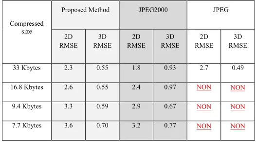
Our approach is compared with JPEG and JPEG2000; these two techniques are used widely in digital image compression, especially for image transmission and video compression. The JPEG technique is based on the 2D DCT applied on the partitioned image into 8x8 blocks, and then each block encoded by RLE and Huffman encoding [4]. The JPEG2000 is based on the multi-level DWT 9/7-daubaches filter, applied on the partitioned image and then each partition quantized and coded by Arithmetic encoding. Most image compression applications allow the user to specify a quality parameter for the compression. If the image quality is increased the compression ratio is decreased and vice versa [5]. The comparison is based on the 2D image and 3D image for test the quality by Root-Mean-Square-Error (RMSE). Tables: 5 and 6 shows the comparison between three methods for Face1, Face2 respectively.
In tables: 5 and 6 "NON" refers JPEG algorithm unable to compress/decompress an image at high compression ratio, while other two methods (our proposed and JPEG2000) are able to compress/decompress successfully. In some cases the 3D RMSE vary, if we compare it with 2D RMSE, this is because the dimensions of original 3D image and 3D decompressed image unmatched. In this case the unmatched regions are discarded. On the other hand, RMSE is not enough to show the real comparison between these three methods. The following figures: 12 and 13 shows the visual properties for the 3D decompressed images: FACE1, FACE2 and FACE3 respectively by using JPEG and JPEG2000 according to compression size for each image.
VII. CONCLUSION
This research has presented and demonstrated a new method for image compression used in 3D applications. The method is based on DWT transformation and JPEG transformation with the proposed Minimize-Matrix-Size algorithm. The results showed that our approach introduced better image quality at higher compression ratios than JPEG and JPEG2000 being capable of accurate 3D reconstructing at higher compression ratios. On the other hand, it is more complex than JPEG2000 and JPEG. The most important aspects of the method and their role in providing high quality image with high compression ratios are discussed as follows:
1- Using two transformations, this helped our compression algorithm to increase the number of high-frequency coefficients, and reduces the low-frequency domains leading to increases compression ratios.
2- The Minimized-Matrix-Size algorithm is used to collect each three coefficients from the AC-matrix, to be single floating-point values. This process converts a matrix into an array, leading to increases compression ratios and keeping the quality of the high-frequency coefficients.
3- The PSS-Algorithm represents the core of our parallel search algorithm to finding the exact original data (i.e. decompression algorithm), which is converts a one-dimensional array (i.e. Minimized-Array) to matrix, and depends on the key-values and Limited-Data.
4- The key-values and Limited-Data are used in coding and
decoding an image, without these information images cannot be reconstructed.
5- Our approach gives better visual image quality compared to JPEG and JPEG2000. This is because our approach removes most of the block artifacts caused by the 8x8 two-dimensional DCT of the JPEG technique and this is because: Minimize-Matrix-Size algorithm. Also our approach uses single level DWT rather than multi-level DWT in JPEG2000, for this reason blurring removed by our approach.
However, the number of steps of the proposed compression and decompression algorithm more than the JPEG and JPEG2000 steps, also the complexity of PSS-algorithm leads to increased execution time for decompression, because the PSS-Algorithm iterative method is particularly complex.
REFERENCES
[1] A. Al-Haj, (2007) Combined DWT-DCT Digital Image Watermarking,
Science Publications, Journal of Computer Science 3 (9): 740-746,.
[2] C.Christopoulos, J. Askelof, and M.Larsson (2000) Efficient methods forencoding regions of interest intheupcoming JPEG 2000 still image coding standard,IEEE Signal Processing Letters,vol.7,no.9. [3] G.SadashivappaandK.V.S.AnandaBabu, (2002) PERFORMANCE
ANALYSIS OF IMAGE CODING USING WAVELETS, IJCSNS
Table 4, Parallel Search algorithm time execution for image: FACE2.bmp
Parameters PSS-Algorithm, P=5 PSS-Algorithm, P=10
Scale –used by quantization
Block size
Total
time(sec.) Total time (sec.)
2 [4x4] 16.27 10.67
2 [8x8] 9.0 7.78
4 [8x8] 3.1 3.77
5 [8x8] 3.0 3.21
Table 6: Sequence of "FACE2.bmp" 2D and 3D decompressed image by three methods, according to compressed size
Compressed size
Proposed Method JPEG2000 JPEG
2D RMSE 3D RMSE 2D RMSE 3D RMSE 2D RMSE 3D RMSE
33 Kbytes 2.3 0.55 1.8 0.93 2.7 0.49
16.8 Kbytes 2.6 0.55 2.4 0.97 NON NON
9.4 Kbytes 3.3 0.59 2.9 0.67 NON NON
[image:6.612.39.295.91.215.2] [image:6.612.325.588.278.424.2]International Journal of Computer Science and Network Security, VOL.8 No.10.
[4] I.E. G.Richardson (2002)VideoCodecDesign, JohnWiley &Sons. [5] K. Sayood, (2000) Introduction to Data Compression, 2nd edition,
Academic Press, Morgan Kaufman Publishers.
[6] M. Rodrigues, A. Robinson and A. Osman, (2010) Efficient 3D data compression through parameterization of free-form surface patches, In: Signal Process and Multimedia Applications (SIGMAP), Proceedings of the 2010 International Conference on. IEEE, 130-135. [7] M. Rodrigues, A. Osman and A. Robinson, (2013) Partial differential
equations for 3D data compression and reconstruction, Journal Advances in Dynamical Systems and Applications, accepted for publication, 2013.
[8] M. M. Siddeq, G. Al-Khafaji, (2013) Applied Minimize-Matrix-Size Algorithm on the Transformed images by DCT and DWT used for image Compression, International Journal of Computer Applications, Vol.70, No. 15.
[9] M. M. Siddeq(2012)Using Sequential Search Algorithm with Single level Discrete Wavelet Transform for Image Compression (SSA-W),
Journal of Advances in Information Technology. Academic Publisher Vol. 3,No. 4.
[10] M. M. Siddeq, M. A. Rodrigues(2014) A Novel Image Compression Algorithm for high resolution 3D Reconstruction,
3D Research. Springer Vol. 5 No.2.DOI 10.1007/s13319-014-0007-6
[11] N. Ahmed, T. Natarajan and K. R. Rao, (1974) Discrete cosine transforms, IEEE Transactions Computer.,” vol. C-23, pp. 90-93.
[12] S. Esakkirajan, T. Veerakumar, V. SenthilMurugan, and P. Navaneethan, (2008) Image Compression Using Multiwavelet
and Multi-stage Vector Quantization, International Journal of Signal Processing Vol. 4, No.4, WASET.
[13] R. C.Gonzalez, R.E.Woods(2001) Digital
ImageProcessing,AddisonWesley publishing company. [14] T. Acharya and P. S. Tsai. (2005) JPEG2000 Standard for Image
Compression: Concepts, Algorithms and VLSI Architectures. New York: John Wiley & Sons.
[15] P. Chen, Jia-Y. Chang (2013) An Adaptive Quantization Scheme for 2-D 2-DWT Coefficients, International Journal of Applied Science and Engineering Vol.11, No. 1.
Fig-8, flowchart of the proposed Decompression Algorithm
(a) 2D BMP “Face1” (c) 2D BMP “Face3”
(a) Decompressed "Face1" 3D image Scale=2, block size =[4x4] 3D texture and shaded
(b) Decompressed "Face1" 3D image (c) Decompressed "Face1" 3D image (d) Decompressed "Face1" 3D image Scale=2, block size=[8x8] 3D shaded Scale=4, block size=[8x8] 3D shaded Scale=5, block size=[8x8] 3D shaded
(e) Decompressed "Face1" 3D image (f) Decompressed "Face1" 3D image, Scale=6, block size=[8x8] 3D shaded Scale=8, block size=[8x8] 3D shaded and texture
Fig-10, (a) Decompressed 3D Face1 image shaded by using high quality parameters applied on the grey-scale image. (b, c, d) Decompressed 3D Face1 image shaded by using normal quality parameters shows the details of 3D surface. (e) Decompressed 3D Face1 image shaded by using low quality parameters and the details of 3D surface still approximately same. (f) Decompressed 3D Face1 image shaded by using very low quality parameters and small amount of the degradation starts appears on the 3D surface.
(a) Decompressed "Face3" 3D image Scale=2, block size =[4x4] 3D texture and shaded (b) Decompressed "Face3" (c) Decompressed "Face3" (d) Decompressed "Face3" 3D image Scale=2, block size=[8x8] Scale=4, block size=[8x8] Scale=5, block size=[8x8] 3D shaded and texture
(a) JPEG2000 (b) JPEG2000 (c) JPEG2000 (d) JPEG2000 51.6 Kbytes 28.4 Kbytes 16.3 Kbytes 13.5 Kbytes
(e) JPEG2000 (f) JPEG2000 (g) JPEG (h) JPEG 11.6 Kbytes 9.0 Kbytes 51.6 Kbytes 28.4 Kbytes
Fig.-12, (a – f) Decompressed FACE1 image by JPEG2000, (g) and (h) Decompressed FACE1 image by JPEG.
(a) JPEG2000 (b) JPEG2000 (c) JPEG2000 (d) JPEG2000 (e) JPEG 33 Kbytes 16.8 Kbytes 9.4 Kbytes 7.7 Kbytes 33 Kbytes
Fig.-13, (a – d) Decompressed FACE3 image by JPEG2000, (e) Decompressed FACE3 image by JPEG.