Abstract—High speed packet access (HSPA) technology is a great achievement in mobile broadband but there is still a need to improve service delivery in order to meet the ever increasing demand for mobile broadband services. Long Term Evolution (LTE) is a 4G Network launched by the 3GPP (Third Generation Partnership project) that provides higher data rate for subscribers at the same time reducing the cost per bit for service providers and much higher overall capacity to deliver more throughputs and reduced latency. This paper provides a technological overview of the benchmarks, prospects and deployment limitation of LTE Network.
Index Terms—3GPP, Long Term Evolution (LTE), Evolved Packet System (EPS), eNodeB, Spectrum
I. INTRODUCTION
ONG Term Evolution (LTE) is a mobile network technology that was developed and deployed by the 3GPP group. Its development was driven by the need to meet the ever growing demand for wireless services. It was designed to support only packet switched services to ensure minimal interference, reduce number of network elements by a simplified architecture, support real time application due to reduced latency, provide simple use and access with greater security and privacy as well as improve spectral efficiency [1].
LTE is deployable in the spectrum bandwidths range from 1.25MHz–20MHz.It evolved from the Universal Mobile Telecommunication System (UMTS) to an all internet protocol based network technology. In the standards, LTE network is based on the Evolved Packet System (EPS) which is made up of the Evolved- UMTS Terrestrial Radio Access Network (E-UTRAN) and the Evolved Packet Core (EPC).The EPS offer IP connectivity between the User Equipment (UE) and the external packet data network [2].
Manuscript received March 23, 2014; revised April 09, 2014.
O. O. Oni is with Department of Electrical and Information Engineering Covenant University, P.M.B. 1023 Ota, Ogun State. Nigeria (phone: 706-672-0365; (e-mail: [email protected]).
A. A. A. Atayero is with Department of Electrical and Information Engineering Covenant University, P.M.B. 1023 Ota, Ogun State. Nigeria (e-mail: [email protected]).
F. E. Idachaba is with Department of Electrical and Information Engineering Covenant University, P.M.B. 1023 Ota, Ogun State. Nigeria (e-mail: [email protected]).
A. S. Alatishe is with Department of Electrical and Information Engineering Covenant University, P.M.B. 1023 Ota, Ogun State. Nigeria (e-mail: [email protected]).
LTE uses Orthogonal Frequency Division Multiple Access (OFDMA) as its radio access for the downlink transmission to enable streaming of data by the use of several narrowband subscribers simultaneously depending on the available bandwidth. Thus, for as many bits transmitted in parallel the transmission speed on each carrier can be lower than the overall resulting data rate. This is to minimize the effect of multipath fading due to different arrival times of the signal while Single carrier Frequency Division Multiple Access was used for data transmission in the uplink transmission.
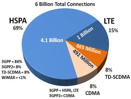
[image:1.595.312.541.463.636.2]The global market share of LTE network is defined by the level of socio economic development in regions world over. As illustrated by the chart in Fig. 1. In 2012, of 6 billion network connections of all kinds, LTE respectably commands 15% of the market share in the world [9].With Asia pacific and Europe undergoing the biggest regional developments of the network [10] as shown in Fig. 2
Fig. 1 Global market share of wireless networks
LTE Networks: Benchmarks, Prospects and
Deployment Limitation
O.O. Oni, A.A.A. Atayero, F.E. Idachaba, A.S. Alatishe, Members, IAENG
Fig. 2.Global LTE market development, 2010-2016
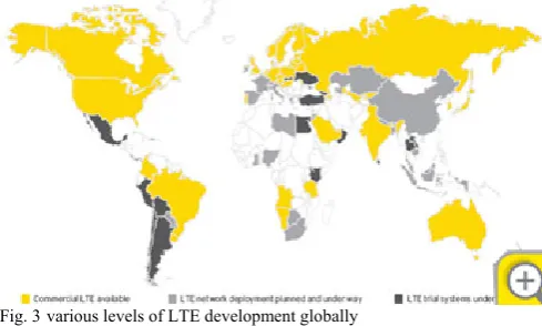
Fig. 3various levels of LTE development globally
[image:2.595.47.292.275.422.2]It is also fair to note that no region of the world is left behind in form of actual development of the network and planned developments in the nearest future [11], [12]. This is shown in Fig. 3&4
Fig. 4.A chart of estimated global LTE regional subscribers
II. BENCHMARKSFORTHELTENETWORK The following specifications are the benchmarks established to define the unique characteristics of an efficient mobile broadband technology [3].
1) Control Plane Latency: 100ms transition time from a
camped state to an active state and below 50ms from an inactive state to an active state.
2) Control Plane Capacity: To sustain at least 200 users in
each cell with at least 5MHz bandwidth in an active state.
3) Peak Data Rate: To support 100Mb/s for its downlink
transmission and 50Mb/s for uplink transmission.
4) User Plane Throughput: Average user throughput is
3-4times HSDPA release 6 in the downlink and 2-3times Enhanced Uplink release 6 in the uplink
5) User Plane Latency: To allow below 5ms transmission
time for small IP packets in unload state.
6) Spectrum Flexibility: To allow radio network operation
in various ranges of spectrum allocations between 1.25MHz to 20MHz in both downlink and uplink direction.
7) Mobility: To sustain network communication at speeds
of up to 500km/h and improve performance for mobile speed between 15 and 120km/h
8) Inter-working and co-existence with 3GPP Radio Access
Technology: Ability of LTE radio network to operate
simultaneously with GSM &UMTS radio networks in a particular location with interruption time less than 300ms in cases of inter system handover.
9) Multicast Broadcast and Multicast Service (MBMS): To
minimize complexity in coding, modulation and UE bandwidth along with MBMS service.
Due to the ever increasing demand for mobile broadband services with the above features, LTE 3GPP has been designed to support packet switched services, IP based flat network architecture.
LTE network is based on the Evolved Packet System (EPS) which comprises the User Equipment, Evolved UMTS Terrestrial Radio Access Network (E-UTRAN) and Evolved Packet Core (EPC) as shown in Fig. 5.
Fig. 5. LTE network architecture
E-UTRAN is situated in the control plane while the Evolved Packet Core (EPC) is located in the user plane towards the User Equipment (UE).
Western Europe
North America
[image:2.595.56.276.521.644.2]A. The E-UTRAN (THE ACCESS NETWORK)
E-UTRAN NodeB (eNB) is a radio base station situated in the control plane that handles all radio related issues within the system and is made up of several eNBs; it provides the E-UTRAN with the required user and control plane execution protocols.
The protocols at the user plane are the Packet Data Convergence Protocol (PDCP), Radio Link Control (RLC), Medium Access Control (MAC) and the Physical Layer (PHY) while protocols at the control plane include all the protocols at the user plane and an additional layer called Radio Resource Control (RRC). The user plane handles user data transmission between the UE and the E-UTRAN while the control plane caters for the signaling and management functions.
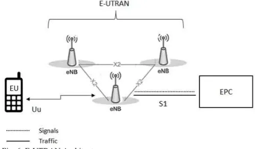
As illustrated in Fig. 6. E-UTRAN architecture is a flat architecture with less complex structure due to reduced number of nodes when compared with previous networks. This allows the base station to perform air interface traffic management single-handedly, perform hard handovers and ensure better Quality of Service [1].
[image:3.595.307.552.49.193.2]The eNBs are interconnected together and can communicate directly with each other by means of the X2 interface while S1 interface allow the eNBs to connect to the EPC shown in Fig. 6. The interface is used to forward IP packet data from the present base station to new base stations. The E-UTRAN is responsible for encryption of all data sent over the interface, Radio Resource Management such as allocation of resources between the eNBs and the UEs, header compression of data streams to ensure efficient use of radio interface and connectivity to the EPC consisting of bearer path towards S-GW and signaling towards the MME.
Fig. 6. E-UTRAN Architecture
[image:3.595.45.295.500.646.2]B. THE EVOLVED PACKET CORE (THE CORE NETWORK)
Fig. 7. EPC Architecture.
The EPC network shown in Fig. 7 is made up of several entities responsible for the overall control of the UE and establishment of the bearers but the main entities and their functionalities are:
Mobility Management Entity (MME) - This is the main control plane entity responsible for tracking the location of mobile devices in idle states. It selects the path between the gateway to internet when a request is made by the mobile device and manages the authorization of security functions. Thus the eNB is connected to the S-GW by the U interface and the MME by the S1-MME interface
The Serving Gateway (S-GW) is responsible for routing and forwarding of IP data packets between the UE and the packet data network gateway, which serves as mobility anchor when the UE moves between the eNBs. It also replicates traffic when there are lawful interceptions and saves the bearer information when UE is in idle state.
Packet Data Network Gateway (PDN-GW) connects the UE to the Packet Data Network and assigns IP address for the UE, performs packet filtering and screening when required and serves as mobility anchor between some 3GPP and non 3GPP technologies such as Wimax and CDMA2000.
III. TECHNOLOGICAL ADVANCEMENT
Since the deployment of LTE release 8 there has been continuous work carried out to meet all the requirement of International Telecommunication Union (ITU) for IMT advanced 4G wireless systems in terms improvement as against other cellular technologies. Release 9 was used mostly to identify areas of corrections and minor improvements where needed.
Other new features and components have been introduced starting from Release 10 and beyond, also known as LTE Advance. The focus of LTE Advance is to meet the different requirement of advance applications such as carrier aggregationschemes[1].
LTE Release 10 provides cost efficient higher data rate and absolutely fulfill ITU requirement for 4G Networks.
Among the novel functionalities introduced are:
and that of which a mobile can receive. It allows a combination of up to five CA of different bandwidth to form a larger bandwidth maximum of 100 MHz as against release 9, whose maximum bandwidth was 20MHz.
Enhanced Multi-antenna Techniques: LTE A has the ability to use 8x8 MIMO for the downlink and 4x4 MIMO for the Uplink. Higher order MIMO improves throughput, spectral efficiency and reduce high Signal to Noise Ratio.
Relay Nodes and Heterogeneous Network were introduced in order to be able to combine both large and small cells of different capacities together to improve cell coverage extension, boost capacity in hotspot areas and connect to remote areas with no fiber connection in order to increase the overall capacity of LTE network.
As LTE Advance continues to evolve, new features were introduced in Release 11 such as Carrier Aggregate Configuration; Coordinated Multi-Point Operation (CoMP).The major reason why CoMP was added is to improve the performance of the network at the cell edges.
Release 12 (final stage release date is schedule for June 2014) [4] focuses on coordination between the cells, capacity, coverage and cost. It addresses the use of matched small and macro cells to improve data rates and efficient usage of spectrum. It also includes New Carrier Type to reduce inter-cell interference and lessen energy consumption.
Furthermore, it is also made up of Enhanced Self-Organizing Networks (SON) for energy saving in small cell capacity area and efficient operation of deployed dense small cell. Finally, the release12 contains Machine Type Communication that permits usage of several devices per cell and allow low energy consumption of devices to ensure lasting battery life.
IV. PROSPECTS OF LTE TECHNOLOGY Let us examine the abundant opportunities and advantages the LTE networks offers for the industry and subscribers alike:
LTE offers a great performance improvement in terms of its ability to operate with smart antennas in other to achieve its target in areas of data rate, capacity and coverage. Multiple Input Multiple Output (MIMO) is one of the most popular Advanced Antenna Technologies that supports LTE and offers higher throughput for a given bandwidth and higher link range for a given power value. MIMOs transceiver and receiver have multiple antennas which are to an advantage to the system considering the number of antennas available at each side.
The main advantage is that the transmitter sends multiple streams on multiple transmit antennas and each of the transmitted streams goes through different path to arrive at each of the receiver antennas. Different paths taken by the stream to reach the multiple receivers improves cancellation
interference error and identifies different symbols on the same frequency by spatial multiplexing [13].
MIMO has the ability to improve overall spectral efficiency e.g. 2*2 LTE MIMO is approximately faster by a ratio 2.5 to that of HSPA [5]. It also offers better Quality of Service, reduced latency and higher link reliability.
LTE offers better spectrum usage and flexibility when compared to other technologies. Radio spectrum for mobile communication is available in different frequency bands in different bandwidths [5].
LTE spectrums are obtainable in bandwidths ranging from 1.25MHz to 20MHz as compared with UMTS that has fixed bandwidth of 5MHz thus making it rigid. It can function in both paired and unpaired spectrum by providing a single radio access that support both Time Division Duplex and Frequency Division Duplex modes such that each mode has its own frame structure and are aligned with each other. Thus it permits same hardware to be used at the terminals and base stations to allow for scale of economy. It also allows Mobile Network Operators to use current spectrum allocation within the bandwidth of 1.25MHz and 20MHz and it can add up blocks of spectrum from different parts of the radio spectrum to create one large bandwidth.
LTE is enjoying strong support from service providers since majority of subscribers are on their GSM/UMTS network who will be interested in the performance advantages LTE offers. Therefore vendors and base stations manufacturers are taking advantage of this huge market to offer compatible devices with the technology to form a multi–vendor market with interoperable products.
This approach has so far brought about cost effective improvement from the existing equipment by reducing the cost of production and increasing choices for subscribers through competition.
LTE base stations have been designed by vendors such that it can use the existing base station sites to proffer the same coverage as GSM and UMTS services. As a result of this many operators have moved to LTE since its value chain of base stations, manufacturers and vendors will create economies of scale and support variety of devices and services.
LTE offers significant Capital and Operational expenditure savings. It improves spectral efficiency and requires less number of nodes to deliver similar network capacity or a greater capacity can be accomplished with similar number of nodes. It also uses a flat Radio Access Network architecture to reduce the number of nodes thus helps operators to maintain their profit margin and reduces carriage cost.
V. DEPLOYMENTLIMITATION
Spectrum Harmonization: One of the major benefits of GSM network is its ability to roam seamlessly across nations and continents due to its harmonized spectrum. However, communication in LTE is designed to operate in different spectrum band ranging from 1.25MHz to 20MHz.This makes LTE to be limited in its state of roaming with operators using different bands. As a result of this it’s unlikely that LTE devices will work on other network than its home network.
The frequency used in different regions varies from one to another. In North America the dominant band ranges between 700/800MHz and 1700/1900MHz while in Europe 800/900/1800/2600MHz is the available bands. Also 1800/2600MHz is the common spectrum in Asia while Australian networks power the technology on 1800MHz.In contrast to all these different bands China and Japan are on completely distinct ones[6].
With LTE standard having several dissimilar frequency bands phones from one country may not work in other countries except the users have phone with multi-band capabilities which can roam freely across the globe.
This is widely considered to be a major limitation to the growth and user acceptance of the technology in the marketplace.
Battery life: This is another challenge that LTE faces. Nokia Siemens network study shows that LTE devices consume 5% to 20% more power than phones from past generation.[7]
A number of factors have been identified to contribute to high power demand in these devices. For example data consumption, immature chipset designs that are not fully integrated may cause high power demand. Moreover, LTE devices use multimedia applications and have larger screen displays which consume more power than other components in the devices.
VI. SIMULATION RESULT OF LTEMODULATION TECHNIQUES
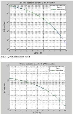
As mentioned earlier LTE uses orthogonal frequency division multiplex (OFDM) for downlink data transmission and allows many users to share a common channel. The modulation can be 2 bits per modulated symbol (QPSK), 4 bits per modulated symbol (16QAM) and 6 bits per modulated symbol (64QAM). This modulation scheme influences the amount of user information transmitted per modulation symbol.
The techniques used are chosen based on their level of signal to interference plus noise ratio (SINR). Lower range modulation is more robust and can tolerate higher levels of interference but provides a lower transmission bit rate and low SINR; while the higher range modulation 64QAM offers a higher bit rate but is more prone to errors due to its
higher sensitivity to interference, noise and channel estimation errors. But it has high SINR.
Subscribers positioned farther from the eNB with lower SINR values use a more robust modulation scheme i.e. lower throughput, while subscribers nearer to the eNB with higher SINR value use less robust modulation schemes i.e. higher throughput
Fig. 8. QPSK simulation result
[image:5.595.303.553.147.537.2]Fig. 9. 16QAM simulation result
VII. CONCLUSION
Efficient transmission of information through limited bandwidth is a challenge in telecommunication industry but with the advancement of LTE technology there has been significant improvement in spectral efficiency and improved services.
The combination of several technologies has enabled the achievement of the goal performance requirements. Thus, its operation on an all-IP flat plus scalable architecture system and reduced protocol complexity has significantly lowered the cost of operation. It has also given improved data rate due to the support of MIMO system.
improve its user acceptance and adaptability globally and also position it to deliver high quality broadcast network of real time multimedia applications to subscribers. The other challenge the network will encounter with mobile subscribers is high energy consumption leading to low battery life due to large number of applications and the screen size resolution.
In addition to these obvious challenges, operators must consider migration strategies from legacy 2G/3G networks, reconsider how services are developed, and deploy IP networks which can deliver low latency end-to-end in order to support real-time QoS. This may include interim device strategies, leasing access on 3rd-party IP networks, implementing IMS architectures, and supporting real-time services like VoIP and streaming video over IP. Operators wanting to implement real-time services like VoIP will have to carefully monitor network latency.
As these challenges are met and LTE is deployed, operators will recognize significant overall cost savings across the network and future revenue opportunities.
ACKNOWLEDGMENT
O.O Oni expresses sincere appreciation to the almighty God for his faithful to me.
REFERENCES
[1] Martin Sauter 3G,4G and beyond: bringing networks, devices and web together -2nd edition p.cm
[2] Aderemi A. Atayero, 3GPP Long Term Evolution: Architecture, Protocols and Interfaces. International Journal of Information and Communication Technology Research volume 1 No. 7, November 2011
[3] "UTRA-UTRAN Long Term Evolution (LTE) and 3GPP System Architecture Evolution (SAE)," Technical Paper
[4] Eiko Seidel, 3GPP LTE-Standardization in Release 12 and Beyond, January 2013page 2
[5] Helen Karapandžić and Terry Norman, Operator strategies for network evolution: the road to LTE March 2009page 6
[6] M. Suneetha Rani et al. / IJAIR , Comparison of Standard Propagation Model (SPM) and Stanford University Interim (SUI) Radio Propagation Models for Long Term Evolution (LTE)
[7] Nokia Siemens Networks, LTE-Advanced The advanced LTE toolbox for more efficient delivery of better user experience
[8] LTE Networks: Evolution and Technology Overview
[9] Informa Telecoms & Media, subscription forecast, November 2012.Available http://www.4gAmericas.org
[10] Benson Wu, Trends in the commercial development of TD-LTE Digitimes Research, Taipei , 14 November 2012
[11] Global mobile Suppliers Association, “Update on Status of LTE deployment,” GSA website, July 2012