Volume 2010, Article ID 737450,11pages doi:10.1155/2010/737450
Research Article
A Novel MPEG Audio Degrouping Algorithm
and Its Architecture Design
Tsung-Han Tsai
Department of Electrical Engineering, National Central University, Taoyuan county 32001, Taiwan Correspondence should be addressed to Tsung-Han Tsai,[email protected]
Received 6 May 2010; Revised 13 August 2010; Accepted 6 November 2010
Academic Editor: Nitendra Rajput
Copyright © 2010 Tsung-Han Tsai. This is an open access article distributed under the Creative Commons Attribution License, which permits unrestricted use, distribution, and reproduction in any medium, provided the original work is properly cited.
Degrouping is the key component in MPEG Layer II audio decoding. It mainly contains the arithmetic operations of division and modulo. So far no dedicated degrouping algorithm and architecture is well realized. In the paper we propose a novel degrouping algorithm and its architecture design with low complexity design consideration. Our approach relies on only using the addition and subtraction instead of the division and modulo arithmetic operations. By use of this technique, it achieves the equivalent result without any loss of accuracy. The proposed design is without any multiplier, divider and ROM table and thus it can reduce the design complexity and chip area. In addition, it does not need any programming effort on numerical analysis. The result shows that it takes the advantages of simple and low cost design. Furthermore, it achieves high efficiency on fixed throughput with only one clock cycle per sample. The VLSI implementation result indicates the gate counts are only 527.
1. Introduction
MPEG audio coding standard is the international standard for the compression of digital audio signals [1]. It can be applied both for audiovisual and audio-only applications to significantly reduce the requirements of transmission bandwidth and data storage with low distortion. The second phase of MPEG, labeled as MPEG-II, aims to support all the normative features listed in MPEG-I audio and provides extension capabilities of multichannel and multilingual audio and on an extension of standard to lower sampling frequencies and lower bit rates [2, 3]. Besides, one of the audio coding, Advanced Audio Coding (AAC), is an international standard which is first created in MPEG-II AAC and the base of MPEG-IV general audio coding [4].
MPEG audio compression standard also defines three layers of compression, named Layer I, II, and III. Each successive layer offers better compression performance, but at a higher complexity and computation cost. Basically Layer I and II are similar and based on subband coding. The difference between them mainly relies on the formation of side information and a finer quantization is provided in Layer II. Layer III is a well-known audio application
and popularly named as MP3. It adopts more complex schemes such as hybrid filterbank, Huffman coding, and nonlinear quantization. From the viewpoint of hardware complexity and achieved quality, Layer II might be a reasonable compromise for general usage. In the official ISO/MPEG subject tests, Layer II codec shows an excellent performance of CD quality at a 128 Kbps per monophonic channel [5]. It has also been adopted in Digital Audio Broadcasting (DAB) standard.
Rescaling Requantization
Degrouping Begin
Input encoded bit stream
Decoding of bit allocation
Decoding of scalefactor
Requantization of samples
Synthesis subband filter
End Output PCM samples
Figure1: MPEG decoding flow chart.
For the recent trend, a universal MPEG audio decoding which can support multiple standards is widely developed and applied in many multimedia and communication devices [8,9]. They solved the common and regular module, synthesis subband with relative improvements. However, they still left some unsolved issue on the other nonregular modules. In fact, degrouping is a must module no matter the target design is on Layer II only, or on a multistandard decoder.
As in the conventional methods, the general purpose CPU, DSP, or ASP (audio signal processor) usually pro-vides some division or modulo instructions to execute the arithmetic operations of degrouping [10–12]. Basically these designs implied either a divider directly, or a multiplier by finding the inverse of the divisor and multiplying the inverse by the dividend. In fact, the numerical analysis methods suffer some low-end general purpose processors that especially the low-end general purpose processors that are initially chosen to play a simple role as a parser or controller. Even for some high-end processors, to support the additional instruction set of division or modulo is also an overhead. Consequently, these approaches will increase the hardware complexity and the chip area. Several techniques used a ROM-based table lookup to replace the multiplier [13, 14]. However, ROM circuit grows exponentially with the dimension of the finite field. Although many fast algo-rithms for computing the division and modulo arithmetic operations have been presented throughout the years [15– 17], these techniques cannot be completely adopted in the MPEG degrouping algorithm. One of the concern is that
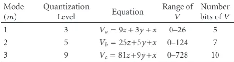
Table1: The relations between the coded sample and the three consecutive subband samples.
Mode (m)
Quantization
Level Equation
Range of
V
Number bits ofV
1 3 Va=9z+ 3y+x 0–26 5
2 5 Vb=25z+5y+x 0–124 7
3 9 Vc=81z+9y+x 0–728 10
these previous methods mainly focused on generating the modulo calculation only. Quotient results are useless for their need. Nevertheless, in degrouping the quotient cannot be skipped because it represents the codeword for the next iteration. So far no dedicated degrouping algorithm and its architecture is investigated.
In the paper, we propose a novel MPEG degrouping algorithm and its architecture design. It is built by using quite different design concept than all the reference works. Our approach relies on just only using the addition and subtraction instead of the traditional division and modulo arithmetic operations, and without any loss of accuracy. It eliminates the need of iterative division computation in original algorithm. Based on the proposed algorithm, no multiplier, divider and ROM table is needed. The design takes the advantages of simple and low cost, and high efficiency result with fixed throughput. It only occupies 527 gate counts with 8.35 ns propagation delay. With this easy-for-use and compact-size design, it is suitably integrated as an Intellectual Property (IP) in System-on-Chip (SOC) design trend.
2. MPEG Degrouping Process
The overall MPEG decoding flow chart is described in Figure1. It includes some major functional blocks: decoding of side information, requantization, and synthesis subband filter bank. Figure 1 also shows a further decomposition of requantization of samples in Layer II application, where degrouping represents an essential component. We describe the grouping and degrouping process in more detail below.
2.1. Grouping. In MPEG audio encoder, given the number
of steps from bit allocation, the samples will be quantized. The further compression feature in Layer II allows two new quantizations, namely, 5-level and 9-level. For these new quantizations plus the former 3-level quantization, sample grouped coding is used. If grouping is required, three consecutive samples are coded as one codeword. Only one value Vj is transmitted for this triplet. For 3-, 5-, and
9-level quantization, a triplet is coded using a 5-, 7-, or 10-bit codeword, respectively. The relationships between the coded value Vj (j = 3, 5, 9) and the three consecutive subband
samplesx,y,zare listed in Table1.
Algorithm DEGROUPING for (i=0;i <3;i+ +) {
s[i]=c%nlevels;
c=(int)c/nlevels; }
where s[i] the reconstructed sample
c the codeword
nlevels the number of quantization steps
Algorithm1: Standard degrouping algorithm.
one bit is saved without any data and precision loss. The same situation on mode 2 results in a saving with two bits, cause a 7-bit codeword can represent three 3-bit samples. In mode 3, two bits are also saved.
2.2. Degrouping. While grouping is used in encoder, it
is necessary to separate the combined sample codeword to several individual samples by degrouping in decoder. According to the grouping equation in Table1, degrouping has to perform the division and modulo operations to separate the three individual samples. This process is defined by MPEG standard algorithm and depicted in Algorithm1. Within the degrouping algorithm, thenlevels can be 3, 5, and 9.
2.3. Design Considerations. Table 3 summarizes the total
arithmetic operations used in MPEG Layer II audio decod-ing. In the whole decoding, a characteristic analysis on the arithmetic operations shows that multiplication and addi-tion are the most common operaaddi-tions where they are mainly applied in synthesis subband filter [18, 19]. Specifically, degrouping only occupies about 1% computation power in the whole MPEG-II decoding process [20]. In SOC design trend, the computation amount is not the only concern. Instead, an easy-for-use issue without additional design effort on overall system should be applicable. Particular, the degrouping arithmetic operations are fully different from any other decoding functions and thus it cannot be shared with other resources. When facing the design of either Layer-II decoding only or a universal MPEG audio decoder, such a little but unavoidable computation engine leads to special design consideration and effort. Consequently, to reduce the circuit overhead and complexity, a low cost and high performance degrouping algorithm and its architecture are necessary.
3. Proposed Algorithm
A degrouping function in MPEG standard includes the division and modulo arithmetic operation. Unlike a straight-forward implementation for these required arithmetic oper-ations, our approach accomplishes it with only a simple addi-tion and shifter operaaddi-tion. We make a mathematical deduc-tion which implies it as a generic formula. In Secdeduc-tion 3.1,
27=128 (values)
25=32 (values)
Grouping Grouping
Grouping
210=1024 (values)
nlevels=9 (4 bits/sample)
nlevels=3 (2 bits/sample)
nlevels=5 (3 bits/sample)
3∗3∗3=27 (values)
5∗5∗5=125 (values)
9∗9∗9=729 (values)
Figure2: Benefits for grouping processing.
a general form is derived. Concerning the specification of degrouping, Section3.2conducts the proposed degrouping algorithm.
To start it, letAand pbe any two positive integers and A, p >0. We can express the general form asA=p·q+r, whereqis the quotient andris the remainder. Besides,Acan be represented as ann-digit tuple:
A=
n−1
i=0
ai·2i
=a0+a1·2 +a2·22+· · ·+an−1·2n−1
= {an−1,an−2,. . .,a1,a0},
(1)
wherean−1,an−2,. . .,a1,a0 ∈[0, 1],n= log2(A+ 1). The operation{} is the simplified expression for a digit-based tuple. From (1), it follows that if p = 2m, then A can be
represented as given below
A=2m·q+r
=
m−1
i=0
ai·2i+ 2m
·am+am+1·2 +am+2·22+ · · ·+an−1·2n−m−1
. (2)
In comparison with (1) and (2),qandrcan be expressed as follows:
q=am+am+1·2 +am+2·22+· · ·+an−1·2n−m−1
=(an−1,an−2,. . .,am+1,am),
r=
m−1
i=0
ai·2i=(am−1,am−2,. . .,a1,a0).
Table2: Calculation and deviation range ofqandr.
Modes Calculation method Deviation range
mode 1 (k=4) q=q1−q2+q3−q4= {a4,a3,a2,a1}−{a4,a3,a2}, +{a4,a3}−{a4} q−1≤q≤q+ 1
r=r
1−r2+r3−r4+r5= {a0} − {a1}+{a2} − {a3}+{a4} −2≤r≤3
mode 2 (k=3) q=q1−q2+q3= {a6,a5,a4,a3,a2} − {a6,a5,a4}+{a6} q−1≤q≤q+ 1
r=r1−r2+r3−r4= {a1,a0} − {a3,a2}+{a5,a4} − {a6} −4≤r≤6
mode 3 (k=3) q=q1−q2+q3= {a9,a8,a7,a6,a5,a4,a3} − {a9,a8,a7,a6}+{a9} q−1≤q≤q+ 1
r=r1−r2+r3−r4= {a2,a1,a0} − {a5,a4,a3}+{a8,a7,a6} − {a9} −8≤r≤14
3.1. General Form as p =2m+ 1. As in (1), letp =2m+ 1,
then m = 1, 2, and 3 are mapping to the three modes of degrouping algorithm, respectively. From the previous discussions, it is expressed as follows:
A=(2m+ 1)·q+r
=2m·q1+r1
=(2m+ 1)·q
1−q1+r1
,
q1=
2m·q2+r2
=(2m+ 1)·q2−q2+r2
,
q2=
2m·q3+r3
=(2m+ 1)·q3−q3+r3
.. .
qk−1=
2m·qk+rk
=(2m+ 1)·qk−qk+rk
,
qk=
2m·qk+1+rk+1
,
=(2m+ 1)·qk+1−qk+1+rk+1
(4)
qk is the k-stage quotient, where it can be recursively
expressed with the next-stage quotient and remainderqk+1 andrk+1. Becauseqk < 2m,qk+1 =0, thusqk = rk+1. From the iterative decomposition of (4), we proceed is as follows:
A=(2m+ 1)·q
1−q1+r1
=(2m+ 1)·q
1−
(2m+ 1)·q
2−q2+r2
+r1
=(2m+ 1)·q
1−q2
+q2+r1−r2
=(2m+ 1)·q1−q2
+(2m+ 1)·q
3−q3+r3
+r1−r2
=(2m+ 1)·q
1−q2+q3
+r1−r2+r3−q3
.. .
=(2m+ 1)·q
1−q2+q3− · · ·+ (−1)k+1·qk
+r1−r2+r3− · · ·+ (−1)k+2·rk+1
.
(5)
Comparing between (2) and (5), let
q=q1−q2+q3− · · ·+ (−1)k+1·qk,
r=r1−r2+r3− · · ·+ (−1)k+2·rk+1.
(6)
q and r are easily calculated. They can be viewed as the approximated results, which are not exactly equivalent to the correct quotient and remainder, q and r. From (6), because 0 ≤ rj ≤ 2m−1, for j =1, 2· · ·k+ 1, the range
ofqandrcan be clarified as follows.
case 1. k=2N, then
− k+ 1
2
·(2m−1)
≤r≤
k+ 1 2
−1
·(2m−1) +2n−k·m−1.
(7)
Substituting(7)into(5), we obtain the range ofqas follows:
q−
(k+ 1)/2 ·(2m−1)
2m
≤q≤q+((k+ 1)/2 −1)·(2
m−1) +2n−k·m−1
2m .
(8)
case 2. k=2N+ 1, then the range ofris
− k+ 1
2
−1
+2n−k·m−1
≤r≤
k+ 1 2
·(2m−1).
(9)
In this case, the range ofqis
q− ⎡ ⎢ ⎢ ⎢
((k+ 1)/2 −1) +2n−k·m−1 2m
⎤ ⎥ ⎥ ⎥
≤q≤q+ (k+ 1)/2 ·(2m−1) 2m
.
(10)
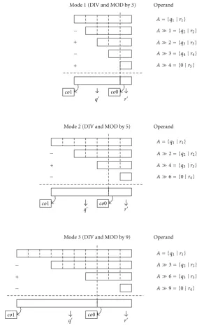
Mode 1 (DIV and MOD by 3) Operand
q r
q r
q r
co0
co0
co0
co1
co1
co1
Mode 2 (DIV and MOD by 5) Operand
−
+
+ −
−
+
−
−
+
−
Mode 3 (DIV and MOD by 9) Operand
A= {q1|r1}
A= {q1|r1}
A= {q1|r1}
A1= {q2|r2}
A2= {q3|r3}
A3= {q4|r4}
A4= {0|r5}
A2= {q2|r2}
A4= {q3|r3}
A6= {0|r4}
A3= {q2|r2}
A6= {q3|r3}
A9= {0|r4}
Figure3: Graphical representation of proposed algorithm for the fast calculation ofqandr.
3.2. Arithmetic Operations for Mode 1, 2, 3. The proposed
algorithm for the calculation ofqandrwith their deviation ranges are illustrated in Table2. It accomplishes the division and modulo by only processing the codeword A, which can be viewed as a 2-tuple representation of qk, rk. Each
intermediate operand, denoted asA mfor convenience, is obtained by shifting rightmbits and dropping rightmost bits ofAafter each shift.
Figure 3 describes a graphical representation of the proposed algorithm for the calculating ofqandrin three modes. It shows that four operands are generated by shifting in mode 2 and 3. Then these operands take the interlacing computations by two subtractions and one addition. In mode 1, five operands are generated and the computation
is achieved by two subtractions and two additions. The addition for the last operand ofA 4, a one digit number, can be viewed as an additional carry for the adder. This approach takes the benefit on reducing one addition in mode 1. More specifically, the processes for all three modes are then equivalent.
Start
Input
A,m
m=1 m=2 m=3
n=5
k=4
n=7
k=3
n=9
k=3
N
A= {an−1· · ·a0} i=1
Y
i=i+ 1
Y N
N
r=r+ (2m+ 1)
q=q−1 r=r
q=q
A=q S=r
Outputs
m?
r≥0 ?
r≥m?
i≤3 ?
q= {an−1· · ·am} − {an−1· · ·a2m}+{an−1· · ·a3m} − {an−1· · ·a4m}
r= {am−1· · ·a0} − {a2m−1· · ·am}+{a3m−1· · ·a2m} − {a4m−1· · ·a3m}
r=r−(2m+ 1) q=q+ 1
Figure4: The overall flow chart for proposed algorithm.
andr, respectively. The detailed flow chart for the proposed algorithm is depicted in Figure4.
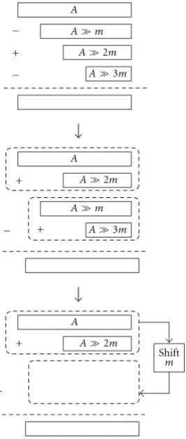
3.3. Data Reordering Scheme. Based on the previous
dis-cussions, the proposed algorithm can be implemented by two subtractions and one addition with four operands: A,A m, A 2m, and A 3m in all three modes. In order to reduce the hardware cost, we use the concept of data reordering to change the data computation flow.
A
A
A
+ +
+ +
− −
−
−
Shift
m
A2m
A2m
A2m
Am
Am
A3m
A3m
Figure5: Data reordering scheme.
4. Architecture Design
In architecture design, the proposed algorithm with data reordering scheme is adopted. Figure 6 shows that the key components of this design include one special adder (SpADD), two subtractors (SUB); and two adders (ADD). Based on the maximum number range of codeword A in mode 3, 10 bit-width bus is assigned forA. The shifter takes the right shift of 2m bits to obtain another operand from A. The SpADD generates a 10-bit sum ofs, and two one-bit carries ofco0,co1.co0 is the carry of addition for 4-bit LSB andco1 is the carry for all-bit addition.
As indicated in Figure 6, the signals of s,co0, andco1 can be demultiplexed into the partial quotients ofq + and q −, and the partial remainders of r + and r −. q +, q −,r + andr −represent the operand with the 2-tuple representation ofqkandrkin Figure3. These partial results
are fed into the two subtractors to generate the q and r. The following two adders take the roles of correcting theq and rinto the real results of qand r. Finally, the operand ofqis fed back and latched in the input register for the use of next degrouping cycle. This approach achieves the fixed throughput with one clock cycle per sample.
The internal architecture of SpADD is illustrated in Figure7. It basically consists of four full adders and six half adders with a ripple-carry architecture. The signal ofc0 is the carry represented as the additional operand in mode 1.
Table3: Arithmetic operations in MPEG Layer II audio decoding.
Classification Function Operations
IQ
Degrouping y=c%a,c=c/d
Requantization y=(x+a)b
Rescaling y=ax
Synthesis IMDCT y=ax+b,y=icixi
Subband IPQMF y=ax,y=iwi
Table4: Comparisons between the original and proposed algo-rithm.
Computation functions
Standard algorithm
Proposed algorithm Original Reordering
Division one — —
Modulo one — —
Addition — one one
Subtraction — two one
The implemented circuit is nonpipelined. However, it can be easily pipelined with the addition of register at every stages. Moreover, this architecture takes the advantages of simple and low cost design, but high efficiency requirement.
5. Comparisons and Experimental Results
In this section, we describe the comparisons and experimen-tal results with our proposed algorithm. The experiments attempt to cover the whole range ofAfor all three modes, as illustrated in Figures8,9, and10. They show the deviations ofq with respect toq, andr with respect tor. From the approximated result ofqandr, and the real result ofqand r, the derivation between them are varied periodically. Some valueqand rare equal toq andr, but some of them are not the same. For example, in mode 1 it shows that when the value ofr is greater than 2, the value ofqis less thanq. When the valueris less than 0, the value ofqis greater than q. Every difference betweenqandqis exactly equal to one.
The comparisons between the standard and proposed algorithm with two schemes are illustrated in Table4. All the computation functions must have the minimum wordlength of 10 bits to satisfy the whole range ofA. In addition, the architectural comparisons between the proposed design and some conventional techniques are shown in Table5.
The proposed degrouping architecture is implemented as an IP with VLSI technical details and summarized in Table6. As the characteristics of regularity and modularity, our novel design only needs 527 gates based on the applied technology. It can run at about 120 MHz which is many times speedup compared with the low operating frequency of 44.1 KHz audio sample rate. It also has the advantages of fix throughput with one clock cycle per sample.
Reg
SpADD
s co0
co1
−1 0 +1
+/−3 +/−5 +/−9 Ctrl
Mode
q +
q −
r +
r −
A 8
5
4 4
10
4
q
r
7
4
7
5 r
q
Codeword A
c0
+
+ −
− 2m
Figure6: The block diagram of degrouping architecture.
FA FA FA FA HA HA HA HA HA HA
C2
S0 S1 S2 S3 S4
0 0
0
A0A0 A1A1 A2A2 A3A3
C3 C4
A4
C5
Mode
S5
A5
C6
S6
A6 A7
S7 S8
C7 C8
A8
C9
S9
A9
co1
co0
C1
C0
Figure7: The internal architecture of SpADD.
0 1 2 3 4 5 6 7 8 9 10
0 2 4 6 8 10 12 14 16 18 20 22 24 26
Value ofA
Deviation value ofq
q q
Va
lu
e
o
f
q
and
q
(a)
−4 −3 −2 −1 0 1 2 3 4
0 2 4 6 8 10 12 14 16 18 20 22 24 26
Value ofA
Deviation value ofr
r r
Va
lu
e
o
f
r
and
r
(b)
Table5: Architectural implementation comparisons between the conventional techniques and the proposed design.
Architecture Computation Throughput Wordlength
Dividor/Modulo DIV/MOD fixed fixed
Serial Dividor/Modulo ADD/SUB not fixed fixed
Multiplier MPY fixed depend on precision of divisor
Lookup ROM Table — fixed 1184 codewords (maximum wordlength: 12 bits)
Proposed Design ADD/SUB fixed (1 sample/cycle) fixed
0 2 4 6 8 10 12 14 16 18 20 22 24 26 28
0 10 20 30 40 50 60 70 80 90 100 110 120
Value ofA
Deviation value ofq
q q
Va
lu
e
o
f
q
and
q
(a)
−5 −4 −3 −2 −1 0 1 2 3 4 5 6 7
0 10 20 30 40 50 60 70 80 90 100 110 120
Value ofA
Deviation value ofr
r r
Va
lu
e
o
f
r
and
r
(b)
Figure9: Experiment results of mode 2 for the deviation value of (a)qwith respect toqand (b)rwith respect tor.
0 4 8 12 16 20 24 28 32 36 40 44 48 52 56 60 64 68 72 76 80 84
0 50 100 150 200 250 300 350 400 450 500 550 600 650 700
Value ofA
Deviation value ofq
q q
Va
lu
e
o
f
q
and
q
(a)
−9 −7 −5 −3 −1 1 3 5 7 9 11 13 15
0 50 100 150 200 250 300 350 400 450 500 550 600 650 700
Value ofA
Deviation value ofr
r r
Va
lu
e
o
f
r
and
r
(b)
Table6: Statistical result of implemented degrouping processor.
Technology 0.35µTSMC 1P4M
Gate count 527
Area 279×265µ2m
Measured propagation delay 8.35 ns
Maximum operation frequency 119.76 MHz
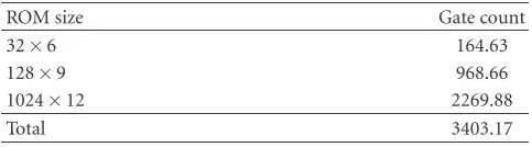
Table7: Implementation result with lookup table.
ROM size Gate count
32×6 164.63
128×9 968.66
1024×12 2269.88
Total 3403.17
Table8: Implementation result with programmable processor.
Processor type Instruction count Cycle count Code size
ARM7TDMI 192 223 1.98 KB
ARM920T 192 142 1.94 KB
with the same VLSI technology. Referring to the codeword size listed in Table 1, three tables are generated optimally and the table word size is 32, 128, and 1024 for three degrouping modes respectively. From the implementation result in Table 7, totally the gate count is more than 3400 including the storage element and decoding circuit. From Table 6, it almost takes seven times of gate count than ours. Another implementation result is listed in Table 8. It is implemented on one of the popular general purpose processor with its two version, ARM7 and ARM9 [21]. The results show that, each processor performs the degrouping iteration with 223 and 142 clock cycles, respectively. For our hardwired degrouping design, only 3 cycles are consumed to acquire the 3 output samples in each iteration. Note that the programmable processor certainly needs the space to store the programming code. In their results almost 2 KB memory are needed. Based on the comparison results, our design can achieve the low complexity and high efficiency considerations, while still keeps the least usage on area.
6. Conclusions
Although only occupying little computation power in the whole decoding process, degrouping process is an essen-tial component in MPEG Layer II audio decoding, espe-cially when meeting the universal MPEG audio decoding requirement. A straightforward design without thorough consideration on algorithm makes an inefficient result. So far no dedicated degrouping algorithm and architecture is developed. We have proposed a novel degrouping algorithm which relies on only using the addition and subtraction instead of the division and modulo arithmetic operations supplied by standard algorithm. It maintains high efficiency without loss of any accuracy. The proposed design is without any multiplier, divider, and ROM table. In addition,
to reduce the arithmetic operations in saving of one sub-tractor, a modified scheme of data reordering is constructed. Based on our algorithm, we propose a degrouping architec-ture with the advantages of simple and low-cost design, and high efficient requirement on fixed throughput. Compared with the general approaches such as direct table lookup or direct programminglevel solution, our method outperforms them either in physical gate count or throughput. It is easily applicable without any programming cost. The VLSI implementation result shows that only 527 gate counts are realized. It is proper to be integrated as a hard IP in the SOC design trend.
References
[1] MPEG, “ISO CD 11172-3: coding of moving pictures and associated audio for digital storage media at up to about 1.5 Mb/s,” November 1991.
[2] MPEG, “ISO CD 13818-3: coding of moving pictures and associated audio for digital storage media at up to about 1.5 Mb/s,” November 1994.
[3] K. Brandenburg and M. Bosi, “Overview of MPEG audio: current and future standards for low-bit-rate audio coding,” Journal of the Audio Engineering Society, vol. 45, no. 1-2, pp. 4– 21, 1997.
[4] MPEG, “ISO CD 13818-7: MPEG-2 Advanced Audio Coding , AAC,” April 1997.
[5] K. R. Rao and J. J. Hwang,Techniques and Standards for Digital Image/Video/Audio Coding, Prentice Hall, Upper Saddle River, NJ, USA, 1996.
[6] S. W. Lee, “Improved algorithm for efficient computation of the forward and backward MDCT in MPEG audio coder,” IEEE Transactions on Circuits and Systems II, vol. 48, no. 10, pp. 990–994, 2001.
[7] T. H. Tsai and Y. C. Yang, “Low power and cost effective VLSI design for an MP3 audio decoder using an optimised synthesis-subband approach,”IEE Proceedings: Computers and Digital Techniques, vol. 151, no. 3, pp. 245–251, 2004. [8] K. H. Bang, N. H. Jeong, J. S. Kim, Y. C. Park, and D. H. Youn,
“Design and VLSI implementation of a digital audio-specific DSP core for MP3/AAC,” IEEE Transactions on Consumer Electronics, vol. 48, no. 3, pp. 790–795, 2002.
[9] T. H. Tsai and C. N. Liu, “A configurable common filterbank processor for multi-standard audio decoder,” IEICE Trans-actions on Fundamentals of Electronics, Communications and Computer Sciences, vol. E90-A, no. 9, pp. 1913–1923, 2007. [10] G. Maturi, “Single chip MPEG audio decoder,”IEEE
Trans-actions on Consumer Electronics, vol. 38, no. 3, pp. 348–356, 1992.
[11] S. C. Han, S. K. Yoo, S. W. Park et al., “An ASIC implemen-tation of the MPEG-2 audio decoder,”IEEE Transactions on Consumer Electronics, vol. 42, no. 3, pp. 540–545, 1996. [12] L. Bergher, X. Figari, F. Frederiksen, M. Froidevaux, J. M.
Gentit, and O. Queinnec, “MPEG audio decoder for consumer applications,” in Proceedings of the 17th Annual Custom Integrated Circuits Conference, pp. 413–416, May 1995. [13] M. A. Soderstrand, “A new hardware implementation of
[14] K. Y. Liu, “Architecture for VLSI design of Reed-Solomon decoders,” IEEE Transactions on Computers, vol. 33, no. 2, pp. 178–189, 1984.
[15] S. Wei and K. Shimizu, “Modulo (2p±1) multipliers using
a three-operand modular addition and booth recoding based on signed-digit number arithmetic,” inProceedings of the IEEE International Symposium on Circuits and Systems, pp. 221–224, May 2003.
[16] T. A. York, B. Srisuchinwong, P. Tsalides, P. J. Hicks, and A. Thanailakis, “Design and VLSI implementation of mod-127 multiplier using cellular automaton-based data compression techniques,”IEE Proceedings E, vol. 138, no. 5, pp. 351–356, 1991.
[17] S. J. Piestrak, “Design of residue generators and multioperand adders modulo 3 built of multioutput threshold circuits,”IEE Proceedings: Computers and Digital Techniques, vol. 141, no. 2, pp. 129–134, 1994.
[18] Y. Jhung and S. Park, “Architecture of dual mode audio filter for AC-3 and MPEG,” in Proceedings of the International Conference on Consumer Electronics (ICCE ’97), pp. 206–207, June 1997.
[19] T. Krishnan and S. Oraintara, “Fast and lossless implemen-tation of the forward and inverse MDCT compuimplemen-tation in MPEG audio coding,” inProceedings of the IEEE International Symposium on Circuits and Systems, vol. 2, pp. 181–184, May 2002.
[20] T. H. Tsai, L. G. Chen, and Y. C. Liu, “A novel MPEG-2 audio decoder with efficient data arrangement and memory configuration,” IEEE Transactions on Consumer Electronics, vol. 43, no. 3, pp. 598–604, 1997.