Available Online At www.ijpret.com
INTERNATIONAL JOURNAL OF PURE AND
APPLIED RESEARCH IN ENGINEERING AND
CFD ANALYSIS OF RECTANGULAR HEAT SINK OF THE VARIABLE FIN PITCH
AMBEPRASAD S
Department of Thermal Engineering, P.C.S.T, R.G.P.V
Accepted Date: 30/10/2012 Publish Date: 01/12/2012 Keywords Fin pitch
Heat transfer coefficient,
Max. Temperature,
Pressure Drop
Corresponding Author
Mr. Ambeprasad S Kushwaha
Department of Thermal Engineering, P.C.S.T, R.G.P.V University, Bhopal.
In electronic equipments at the data centers where large server are involved, thermal management is one of the important topics of current research.
with modern life, for instance appliances, instruments and computer specifications. The dissipation of heat is necessary for its proper function. The heat is generated by the resistance encountered by electric current. Unless proper cooling arrangement is designed, the operating temperature exceeds permissible limit. As a consequence, chances of failure get increased. For more than a decade, investigations have been conducted to better understand the flui flow and heat transfer characteristics in heat sinks designed for applications in electronic cooling. Heat sink is an environment or objects that absorbs heat and dissipates heat from another using thermal contact (either direct or radiant). And it is on
commonly used devices for enhancing heat transfer in electronics components. This project is about the of study rectangular heat sink having variable fin pitch using ANSYS WORKBENCH version 14.1. The main objective of our analysis is to study the
pitch on the heat transfer, pressure drop, surface heat transfer coefficient. In this project the optimal fin dimension is taken from and geometry is made, the optimal geometric parameter is as followed fin height, fin thickness, ba
mm, 8 mm and 4mm,here all the fin parameter is kept constant and only fin pitch is varied as 2mm, 4mm, 6mm, to study the effect. The air velocity is taken as 15 CFM and the heat input of 100w is provided. IJPRET-QR CODE
Available Online At www.ijpret.com
INTERNATIONAL JOURNAL OF PURE AND
APPLIED RESEARCH IN ENGINEERING AND
TECHNOLOGY
A PATH FOR HORIZING YOUR INNOVATIVE WORKCFD ANALYSIS OF RECTANGULAR HEAT SINK OF THE VARIABLE FIN PITCH
AMBEPRASAD S KUSHWAHA, Prof. RAVINDRA KIRAR
Department of Thermal Engineering, P.C.S.T, R.G.P.V University, Bhopal.
Abstract
In electronic equipments at the data centers where large server are involved, thermal management is one of the important topics of current research. These electronic equipments are virtually synonyms with modern life, for instance appliances, instruments and computer specifications. The dissipation of heat is necessary for its proper function. The heat is generated by the resistance encountered by ctric current. Unless proper cooling arrangement is designed, the operating temperature exceeds permissible limit. As a consequence, chances of failure get increased. For more than a decade, investigations have been conducted to better understand the flui flow and heat transfer characteristics in heat sinks designed for applications in electronic cooling. Heat sink is an environment or objects that absorbs heat and dissipates heat from another using thermal contact (either direct or radiant). And it is on
commonly used devices for enhancing heat transfer in electronics components. This project is about the of study rectangular heat sink having variable fin pitch using ANSYS WORKBENCH version 14.1. The main objective of our analysis is to study the
pitch on the heat transfer, pressure drop, surface heat transfer coefficient. In this project the optimal fin dimension is taken from and geometry is made, the optimal geometric parameter is as followed fin height, fin thickness, base height and fin pitch 48 mm, 1.6 mm, 8 mm and 4mm,here all the fin parameter is kept constant and only fin pitch is varied as 2mm, 4mm, 6mm, to study the effect. The air velocity is taken as 15 CFM and the heat input of 100w is provided.
INTERNATIONAL JOURNAL OF PURE AND
APPLIED RESEARCH IN ENGINEERING AND
A PATH FOR HORIZING YOUR INNOVATIVE WORK
CFD ANALYSIS OF RECTANGULAR HEAT SINK OF THE VARIABLE FIN PITCH
KIRAR
Department of Thermal Engineering, P.C.S.T, R.G.P.V
In electronic equipments at the data centers where large server are involved, thermal management is one of the important topics of These electronic equipments are virtually synonyms with modern life, for instance appliances, instruments and computer specifications. The dissipation of heat is necessary for its proper function. The heat is generated by the resistance encountered by ctric current. Unless proper cooling arrangement is designed, the operating temperature exceeds permissible limit. As a consequence, chances of failure get increased. For more than a decade, investigations have been conducted to better understand the fluid flow and heat transfer characteristics in heat sinks designed for applications in electronic cooling. Heat sink is an environment or objects that absorbs heat and dissipates heat from another using thermal contact (either direct or radiant). And it is one of the commonly used devices for enhancing heat transfer in electronics components. This project is about the of study rectangular heat sink having variable fin pitch using ANSYS WORKBENCH version 14.1. The main objective of our analysis is to study the effect of variable fin pitch on the heat transfer, pressure drop, surface heat transfer coefficient. In this project the optimal fin dimension is taken from1 and geometry is made, the optimal geometric parameter is as
se height and fin pitch 48 mm, 1.6 mm, 8 mm and 4mm,here all the fin parameter is kept constant and only fin pitch is varied as 2mm, 4mm, 6mm, to study the effect. The air velocity is taken as 15 CFM and the heat input of 100w is provided.
Available Online At www.ijpret.com
INTRODUCTION
Extended surfaces or fins are commonly
found on electronic components ranging
from power supplies to transformers. The
fins serve to increase the surface area
thorough which heat is transferred to the
surrounding environment by natural
convection. Due to the rapid growth of
electronic technology, electronic appliances
and devices now are always in our daily life.
Users prefer computers of higher
performance and are therefore more willing
to spend reasonably on them. This
tendency has motivated the manufacturers
to employ overdrive technology to improve
their products. With this technology, these
devices are capable of processing more
data within a given period of time and the
system performance is therefore regarded
as higher. However, this capability is
directly related to its heat generation .The
larger the amount of data the system
processes at a time, the greater the amount
of heat it generates. The performance of
these devices is directly related to the
temperature; therefore it is a crucial issue
to maintain the electronics at acceptable
temperature levels. The dissipation and
subsequent rejection of potentially
destructive self produced heat is an
important aspect of electronic equipment
design. The most common method for
cooling electronic devices is by finned heat
sinks made of aluminum. These heat sinks
provide a large surface area for the
dissipation of heat and effectively reduce
the thermal resistance. In order to design
an effective heat sink, some criterions such
as a large heat transfer rate, a low pressure
drop, an easier manufacturing, a simpler
structure, a reasonable cost and so on
should be considered. As heat sinks are
used in most electronics applications, the
race for selecting a particular design of heat
sink or more specifically a particular fin
cross sectional profile remains somewhat
undefined. Unfortunately, heat sinks often
take up much space and contribute to the
weight and cost of the product.
Consequently, the need for new design and
more effective ways to dissipate this energy
is becoming increasing urgent.
THEORETICAL FORMULATION
The energy balance equation for an
element having rectangular fins made of
Available Online At www.ijpret.com The rate of heat conduction into the
element = rate of heat conduction out of
element + rate of heat convection from the
element surface
The rate of heat conduction in the element
is the function of distance x which can be
given as
(1)
By using element surface area dAs=pdx, we
get
(2)
(3)
The general solution of the equation is
(4)
Let us assume that the fin is of finite length
and loss of heat from its tip is convective.
The boundary conditions are
By using this boundary condition and
rearranging the equation, we get
MODELINGANDSIMULATION
CFD codes are structured around the
numerical algorithms that can be tackle
fluid problems. In order to provide easy
access to their solving power all commercial
CFD packages include sophisticated user
interfaces input problem parameters and to
examine the results. Hence all codes
contain three main elements: In CFD
calculations, there are three main steps
1. Pre-processing.
2. Solver
3. Post processing.
PRE-PROCESSING: Pre-Processing is the
step where the modeling goals are
determined and computational grid is
created. Preprocessor consists of input of a
Available Online At www.ijpret.com friendly interface and subsequent
transformation of this input into form of
suitable for the use by the solver.
The user activities at the Pre-processing
stage involve: Definition of the geometry of
the region:
The computational domain. Grid generation
is the subdivision of the domain into a
number of smaller, non-overlapping sub
domains (or control volumes or elements
Selection of physical or chemical
phenomena that need to be modeled).
Definition of fluid properties: Specification
of appropriate boundary conditions at cells,
which coincide with or touch the boundary.
The solution of a flow problem (velocity,
pressure, temperature etc.) is defined at
nodes inside each cell. The accuracy of CFD
solutions is governed by number of cells in
the grid. In general, the larger numbers of
cells better the solution accuracy. Both the
accuracy of the solution & its cost in terms
of necessary computer hardware &
calculation time are dependent on the
fineness of the grid. Efforts are underway to
develop CFD codes with a (self) adaptive
meshing capability. Ultimately such
programs will automatically refine the grid
in areas of rapid variation.
SOLVER EXECUTION: In the second step
numerical models and boundary conditions
are set to start up the solver. Solver runs
until the convergence is reached. There are
three distinct streams of numerical
solutions techniques: finite difference, finite
volume& finite element methods. In outline
the numerical methods that form the basis
of solver performs the following steps. The
approximation of unknown flow variables
are by means of simple functions.
Discretization by substitution of the
approximation into the governing flow
equations & subsequent mathematical
manipulations.
POST-PROCESSING: As in the
pre-processing huge amount of development
work has recently has taken place in the
post processing field.
Governing Equations of Fluid Flow
The most general form of fluid flow and
heat transfer equations of compressible
Newtonian fluid with time dependency
Available Online At www.ijpret.com Continuity Equation
Momentum Equation
Energy Equation
CFD SIMULATIONS
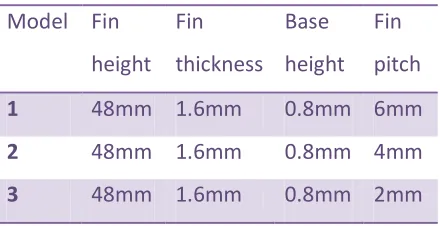
The geometric parameters of the heat sink
chosen for the present study are given in
Table 1. Considering the various geometric
variables present, models are created in
Uni-graphics NX-6 and simulation are
carried out using Fluent 14.1 to determine
the output parameters like maximum
temperature, pressure drop, surface heat
transfer coefficient .The number of fin is
kept constant as increase in the number of
fins has an adverse effect of increase in
pressure drop.
Table 1 Geometric parameters
Model Fin
height Fin
thickness Base
height Fin
pitch
1 48mm 1.6mm 0.8mm 6mm
2 48mm 1.6mm 0.8mm 4mm
Available Online At www.ijpret.com RESULTS AND DISCUSSIONS
Table.2 Result
Fin
pitch
(mm)
Overall
Heat
transfer
coefficient
(w/m2k)
pressure
drop
(Pascal)
Max.
Temperature
(k)
2 34.16299 92.48031 356.636
4 32.23675 18.88845 364.8125
6 26.85737 7.199409 369.0408
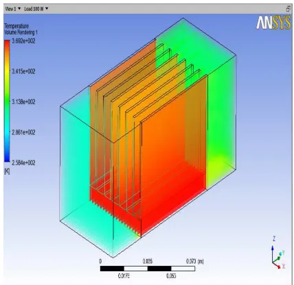
Figure 1 contour of static temperature of
heat sink of fin pitch 6mm for 100w heat
input
Figure 2 contour of static temperature of
heat sink of fin pitch 4mm for 100w heat
input
Figure 3 contour of static temperature of
heat sink of fin pitch 2mm for 100w heat
Available Online At www.ijpret.com Graph 1 Fin pitch v/s overall heat transfer
coef.
Graph 2 Fin pitch v/s pressure drop
Graph 3 Fin pitch v/s Max Temperature
From the above graphs
Graph 1 indicates as the fin pitch increases
overall heat transfer coefficient decreases.
As per further studies we know that to
acquire minimum temperature the heat
transfer coefficient should be more
herefrom the above result the heat sink
with fin pitch 2 mm has more heat transfer
coefficient
Graph 2 indicates as the fin pitch increases
Values of the maximum temperature
increases
Similarly here also the heat sink with fin
pitch 2 mm shows minimum temperature
attained.
Graph 3 indicates as the fin pitch increases
Pressure drop decreases.but for the
satisfactory result the pressure drop should
be minimum. Here in case of 2 mm fin pitch
the pressure drop is 92.4803 pa and with 4
mm pitch 18.88 pa and with 6 mm 7.19 pa
so the heat sink with pitch 6 mm satisfies.
but it shows the max temp which is un
avoidable.
So understanding all the conditions the heat
sink with pitch 4mm should be selectes as it
0 20 40 60 80 100
1 2 3
finpitch
pr.drop
0 100 200 300 400
1 2 3
finpitch
Available Online At www.ijpret.com has all the optimum values.as we can’t
select fin with pitch 2mm as it has high
pressure drop, though it has minimum
temperature attained.And that to we
cannot select heat sink with in pitch 6mm
as it has maximum temperature though it
has least pressure drop and the heat sink
with fin pitch 4mm shows the optimum
values of all the three parameter and the
result found to be in good agreement with
conclusion drawn by Arularasan R.and
Velraj R1.
REFERENCES
1. Arularasan R and Velraj R, CFD Analysis
in a Heat sink for cooling of Electronic
devices, International Journal of The
Computer, the Internet and Management
2008; 16(3): 1-11.
2. Vafai K, Zhu Lu, Analysis of two-layered
micro channel heat sink concept in
electronic cooling, International Journal of
Heat and Mass Transfer, 1999; 42:
2287-2297.
3. Shashank Deorah, CFD Analysis of a
vertical tube having internal fins for the
Natural Convection.
4. Kai shing yang and Yur tsai lin, Heat
transfer characteristic of heat sink influence
of fin spacing at low Reynolds number
region, International journal of Heat and
Mass Transfer, 2010; 53(25-26).
5. Behnia M, Copeland D, and Sood
phadakee D, A Comparison of Heat Sink
Geometries for Laminar Forced
Convection,” Proceedings of The Sixth
Intersociety Conference on Thermal and
Thermo mechanical Phenomenon
Electronic Systems, Seattle, Washington,
USA 1998: 27–30, 310–315.
6. Mohsin, Optimization of Cylindrical
Pin-fin heat sinks using Genetic Algorithm” IEEE
Transactions on components and packaging