Using Delta-Sigma Modulators in Adaptive
Modulated Visible Light OFDM Systems
Sanjana C Saju,
Agi Joseph GeorgeStudent, Dept. of ECE, AmalJyothi College of Engineering Kanjirappally, Kottayam, India
Assistant Professor, Dept. of ECE, AmalJyothi College of Engineering Kanjirappally, Kottayam, India
ABSTRACT: The use of OFDM in optical wireless data transmission is due to its high data rate compared to other transmission methods. Adaptive modulation is a technique used for maximizing the data throughput of subcarriers allocated to a user in OFDM system. A major limitation of existing visible light communication (VLC) systems is the limited modulation bandwidth of light-emitting diodes used in the system. The Optical OFDM (O-OFDM) is sensitive to the non-linear effects of LED. The proposed method is to use a delta-sigma modulator to convert a continuous magnitude OFDM digital signal into a two level analog signal. This signal will be given as the input of a LED. By this the output of LED is equivalent to the output of on-off keying (OOK) signal and thus it is immune to the non-linearity. Simulation results validate that the proposed system improves the VLC system performance.
KEYWORDS: VLC, VLC-OFDM, Adaptive Modulation, Delta Sigma Modulator
I. INTRODUCTION
Visible light communication (VLC) is a type of wireless communication by using light as the medium for transmission. Visible light is the data communication medium which covers 400 and 800THz (375 to 780nm) in the Electromagnetic Spectrum. In VLC the visible light is a constant beam of photons emitted from light source by applying constant current. When the current varies at very high speed, the output of light also varies and is detected by a photo-detector. This fast variation of light cannot be detected by human eyes and we feel constant lightning from light source. Li-Fi technology means the communication by the use of light, i.e by using visible light. It is similar to Wi-Fi technology by using RF communication. The term Li-Fi was first introduced by the German physicist Prof. Harald Haas.
Optical wireless communication (OWC) is general term which refers to all types of optical communications where cables (optical fibers) are not used. Both Wi-Fi (Wireless Fidelity) and Li-Fi (Light Fidelity) transmit data over the electromagnetic spectrum. The difference is that Wi-Fi utilizes radio waves whereas Li-Fi uses visible light. It is the fast and cheap wireless communication system which is optical version of the Wi-Fi. Li-Fi is a high speed, bi-directional and fully networked wireless communications like Wi-Fi using light. It is a subset of OWC and can be a complement or sometimes a replacement to RF communication (Wi-Fi or cellular network) in contexts of data broadcasting. The transmission is not only a single data streams, in this technology the transmission is thousands of data streams in parallel in higher speeds and the technology is called Orthogonal Frequency Division Multiplexing (OFDM).
OFDM is now increasingly being used as a modulation technique for optical system because when comparing, OFDM has better optical power efficiency than conventional modulation schemes such as On-Off keying (OOK) and Pulse Position Modulation (PPM) is in [1]. In conventional OFDM system the transmitted signals are bipolar and complex. The intensity of the light cannot be negative, so the bipolar signals used in OFDM cannot be used in O-OFDM. Here only the intensity of the signal is modulated and detected and thus, the signal is constrained to be real and positive. Therefore, the conventional OFDM system, which involves complex signaling, needs to be modified. For a system based on discrete Fourier transform (DFT), the technique to make the transmitted signal real is to convert the input signal into a Hermitian symmetric signal before it is fed to the inverse fast Fourier transform (IFFT) operation in an OFDM transmitter. Hermitian symmetric signal is a signal in which the complex conjugate of the first half is the same as the second half.
that they were not visible to humans and yet still functional. The US Federal Communication Commission has warned of a potential spectrum crisis because Wi-Fi is close to full capacity, Li-Fi has almost no limitations on capacity and the spectrum is unlicensed. The visible light spectrum is 10,000 times larger than the entire radio frequency spectrum. Using light is very easily because we have the infrastructure already. Only thing to do is to replace all other types of bulbs with LEDs. LEDs are semi-conductors and an electronic device, and it has a property that its intensity can be modulated at a very high speed. This is the basis of in this technology. VLC,which is an optical wireless technology using the visiblespectrum, is growing fast is in [2]. The benefits, techniques, potentialapplications and challenges of VLC can be found in [3].
Visible light Communication is commonly implemented using white LED light bulbs. These devices are normally used for illumination by applying a constant current through the LED. The optical output can be made to vary at extreme high speeds by the fast and subtle variations of the current. This variations cannot be visualized by human eye, but this variation can be used to carries data at high speed. The main goals of the system is to increase the data rate of wireless communication and to create the communication by using existing devices and to reduce the cost of communication.White LEDs have been used as light sources replacing incandescent light bulbs and fluorescent lamps is in [4] and [7].
This is because LEDs have many advantages both in communication and lightingpurposes. It has longer life time (on average, LEDs last three to five times longer thanfluorescent and 20 to 30 times longer than incandescent light) compared other. It also having high brightness (3 watt LED can produce as much illumination as a 45 watt incandescent light bulb).The energy consumption of LED is too low. Fast switching due to an LED's short response time, it can modulate easily for the purpose of communication. The LED lighting can be equipped with various shapes which were difficult with traditional lightings such as incandescent bulbs and fluorescent lamps. The low cost, low electric power consumption and long life expectancy are the considerable advantages. The possibility of high-speed data communication is the indispensable characteristic for using LED infrastructure for lighting as communication devices.
Optical OFDM (O-OFDM) is commonly used for short range indoor wireless system. The conventional OFDM using cannot be directly used to optical systems. Here the intensity modulation with direct detection (IM/DD) is used as the carrier modulation and demodulation method. IM/DD is the common, simple and low cost optical carrier modulation and demodulation method for optical wireless systems. There are many ways to modulate a transmitted optical signal in Optical communication system. The phase/frequency, intensity, or polarization of the optical signal can be modulated. The intensity modulating is commonly used one, this is because it is the type of modulation which is easy to implement. In this the optical output power of the source is simply varied in accordance with the modulating signal. It is easy to detect the optical signal produced. The modulating signal is easily retained from the output of a photo-diode placed in the receiver section. This method is called Direct detection.
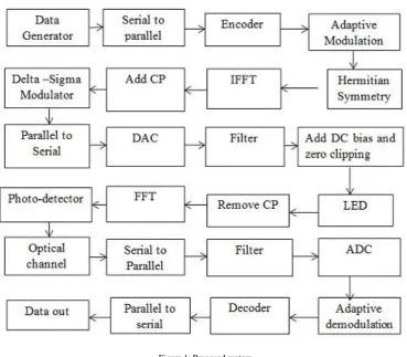
VLC-OFDM is the modification of conventional OFDM.The main goal of O-OFDM is to increase the data rate in accordance with established optical modulation techniques. The additional blocks in this compared to OFDM are Hermitian Symmetry, LED which is used to convert the electrical signal into optical signal and the photo-detector which is used to convert the optical signal into electric signal. In the transmitter section, initially a stream of data is received as an input signal. The serial to parallel converter separates the stream of data into parallel form. Then the mapping process which obtained different symbols depends upon the modulation used. Usually in OFDM the modulations used are PSK and QAM. Then the Hermitian Symmetry is used. By the use of this the output of IFFT obtains only real values. Once the modulation is done the serial to parallel process is executed and then the cyclic prefix is added. Output of this process is given to the Digital to Analog Converter (DAC). Then each of the signal is filtered by using a Low Pass Filter (LPF) to shape the pulses and avoiding the aliasing effect (Aliasing is an effect in signal processing that cause different signals to become indistinguishable among each other sampled, one signal becomes an alias of the other). Then the LED trasmits the data through the optical channel in the form of light and photo-detector at the receiver section receives the signal. Then the reverse process of receiver part is done and finally the transmitted output is retained.
IFFT present in the transmitter section and FFT present in the receiver section are the main functions in the system which distinguishes OFDM from single carrier systems. The input to the IFFT is the complex vector X, it is represented
as = 𝑋0, 𝑋1 , 𝑋2 , … … … … . 𝑋𝑁−1 , the vector has length N where N is the size of the IFFT. Each of the elements of X
In OFDM system the transmitted signals are bipolar and complex. These signals cannot be transmitted in an IM/DD system. This is because the intensity of light cannot be negative. OFDM signals designed for IM/DD system must therefore be real and non-negative. There are different forms of OFDM for IM/DD system. Here using the DC biased optical OFDM (DCO-OFDM) system. In DCO-OFDM all the subcarriers carries data symbols. The input X to the IFFT is complex. This data signal is constrained to have Hermitian Symmetry.
𝑋𝑚 = 𝑋∗𝑁−𝑚 𝑓𝑜𝑟 0 < 𝑚 <𝑁
2(1)
where * represent complex conjugate. The two components 𝑋0 and 𝑋𝑁 2are set to zero. Due to the Hermitian symmetry applied to the input signal to the IFFT, the output of the IFFT, i.e. 𝑥, which is real not complex. Then the input signal 𝑋becomes𝑋 = 0, 𝑋1 , 𝑋2 , … … … … . 𝑋𝑁 2 −1 ,0, 𝑋𝑁 2∗ −1 , … … … … . 𝑋2∗, 𝑋1∗ . The 𝑘𝑡ℎ time domain sample of 𝑥 is 𝑥𝑘 and is given by,
𝑥𝑘 =
1
𝑁 𝑋𝑚𝑒𝑥𝑝
𝑗 2𝜋𝑘𝑚 𝑁 𝑁−1
𝑚 =0 (2)
where𝑁is the number of points on the IFFT and 𝑋𝑚 is the 𝑚𝑡ℎsubcarrier of signal. Thenumber of unique data carrying
subcarriers present in DCO-OFDM is (N/2) - 1. In DCO-OFDM a dc bias is added after the filtering process to make the signal positive. OFDMsignal have a high peak to average power ratio. Due to this a very high value of DC biasis required to eliminate all negative peaks. If a large DC bias is used, the optical energyper- bit to single sided noise power spectral density becomes very large. This results the system to be inefficient in terms of optical power. So for DC biasing a moderate bias is used and the remaining negative peaks are clipped which obtains a clipping noise. In typical DCO-OFDM systems all the subcarriers carries data symbols and the clipping noise affects all the subcarriers. Any negative peak which remains after the addition of DC bias level is clipped at zero.
Here using the adaptive modulation method to increase the efficiency. It is to provide balance between Bit Error Rate (BER) and Signal to Noise ratio (SNR) through the improvement of the spectral efficiency. In an OFDM transmission system the subcarriers used to transmit data are attenuated individually under the frequency selective fading and flat fading channel. But the performance of the channel may be highly fluctuating across the subcarriers and changes from symbol to symbol. The error probability is dominated by the OFDM subcarriers with highest attenuation with a poor performance becomes the result when the same fixed transmission method is used. Therefore in the case of frequency selective fading when the SNR increased then the error probability decreases very slowly. This problem can be mitigated by using different modulation methods for individual OFDM subcarriers. This will increases the performance and data throughput of an OFDM system. The basic idea is to adapt different order modulations is that to allow sending more bits per symbol and thus achieving higher throughput or better spectral efficiencies is in [5] and [6]. According to the results obtained by Czylwik in [13] it can be see that while using adaptive modulation instead of fixed modulation, the BER target 10−3 can be reduced by 5dB to 15dB. Using of different order modulations allows sending more bits
per symbol and thus achieving better efficiencies.
In [11] and [12] the switching between the modulation schemes is done for maintain a BER less than 10−3. When the
SNR is less than 7dB then no data is being transmitted. If SNR is between 8 and 17, then BPSK modulation is used. If SNR is between 17 and 22.5, then 16-QAM is used. If SNR is 22.5 and above then 64-QAM is used. In a VLC system the modulation bandwidth of the LED is limited. The application of spectral efficient modulation schemes with high Peak to average Power ratio is prevented by non linearity in the LED. In [9] a one-bit delta sigma modulator is used in the transmitted signal. By this the nonlinear effects of the LED has been avoided and the system achieves better performance. In [10] the optimal DAC noise shape for minimizing information loss given a power constraint.
II. PROPOSED SYSTEM
Figure 1: Proposed system
Delta Sigma Modulator is used for a process called digital signal processing which is used for encoding analog signal into digital signals as found in an ADC or to convert digital signal into analog signals as found in an DAC. DAC is used to transfer higher resolution digital signals into lower resolution digital signals. The first step of this process is delta modulation. In this the change in the signal is encoded, rather than the absolute value. The result of this is a stream of pulses, as opposed to a stream of numbers as in the case of Pulse Code Modulation (PCM).
By passing the digital output through a 1-bit DAC and adding (sigma) the resulting analog signal to the input signal the accuracy of the modulation can be improved. By this the error introduced by the delta modulation is being reduced. This technique is now increasingly used in modern electronic components because of its efficiency and reduced circuit complexity. A delta sigma DAC encodes a high resolution digital input signal into a lower resolution output signal but higher sample frequency signal that is mapped to voltages. Then it is smoothed with an analog filter in both cases. Temporary use of lower resolution signal simplifies circuit design and improves efficiency. The coarsely quantized output of a Delta-Sigma Modulator is occasionally used directly in signal processing or as a representation for signal storage.
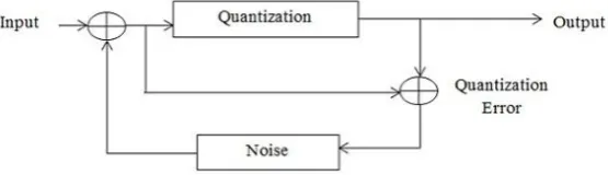
There are two types of quantization error in DM. They are slope overload distortion and granular noise. Slope over load distortion occurs when the input signal is changing much more rapidly than that can be tracked. When the DM tracks a relatively flat i.e. slowly changing input signal, then the granular noise occurs. For minimizing slope over load, the step size has to be increased but then increasing will cause more error due to quantization noise. The two types of distortions can be reduced by the use of an integrator in front of the DM. This has two effects. First it amplifies the low frequencies and increases the correlation of the signal into the DM input. Second is it simplifies the DM decoder because the differentiator required at the decoder is cancelled by the DM integrator. Furthermore the 2 integrators at the encoder can be replaced by a single integrator before the comparator. This system is known as sigma delta modulation (SDM). With the integrator (sigma) placed in front of the difference computation block (delta), the transmitter signal is not modified. Figure 2 shows the block diagram of Delta Sigma Modulator and the benefits of using this in VLC-OFDM is in [8] and [9].
Figure 4.1: Delta-Sigma Modulator
In Delta-Sigma Modulator the output can be expressed as Y = X + (1 + N)Q (3)
where Y is the output, X is the input, N is the noise and Q is the Quantization error of the Delta Sigma Modulator.Quantization noise gets filtered when it is passed through a system. The implication is that quantization error which is spread over the bandwidth is multiplied by the frequency response. As a result, the noise inside the signal bandwidth gets attenuated, and amplified the noise outside the signal bandwidth. Better signal to quantization noise ratio is the result of filtering of the noise outside the signal bandwidth. In this sigma delta modulator the quantization noise is shaped by a first order filter and the doubling of sampling frequency results in reduction of noise power.By this the circuit complexity can be reduced and the overall system performance can be improved. This will be described in the simulation results. From [9] and [10] we can see that the VLC OFDM with sigma delta modulation can significantly improve the overall system performance in terms of bit error rate. In [10] and [14] also explains the benefits of Delta Sigma Modulator.The main function of Delta Sigma DAC is to converts a many level lower rate signal into a few level higher rate signal by maintaining high in band SNR. In the transmission path the information bits are modulated to time domain signals by the modulation block and the modulated signal is converted to analog domain signal by a Digital to AnalogConverter(DAC). To ensure that the input of the LED signal works in the operational region, a Direct Current (DC) bias is required. In the receive path a photodiode(PD) is used to detect the light intensity. In the receiver section the analog signal is sampled by theanalog to digital converter(ADC) and is then processed by the demodulation block.LED is non-linear device and also the modulation bandwidth of the LED is limited. DCO-OFDM siganls are very much sensitive to the non-linearity of the LED, when the input signal is large.In order to get ridof the influence of the nonlinearity of LED, a one-bit SDM canbe applied to the system. The SDM is placedbefore the DAC. The multi-level input signal is quantized intotwo-level output signal with the SDM.With the SDM, the quantization noise of the one-bit quantizeris filtered by the loop response, which exhibits highpassfilter effects.
III. SIMULATION RESULTS
total number of transferred bits during a studied time interval. BER has been measured by comparing the transmitted signal with the received signal and computing the error count over the total number of bits. For any given modulation, the BER is normally expressed in terms of signal to noise ratio (SNR). SNR is defined as the ratio between signal power to noise power and it is normally expressed in decibel (dB).
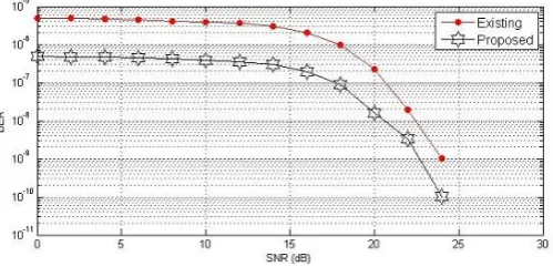
Simulation results shows the BER versus SNR graph of adaptive modulated visible light OFDM system and the proposed system which uses the Delta sigma modulator.
Figure 3: SNR between 8 and 17 using QPSK
Figure 3 shows the BER versus SNR graph when the SNR is between 8 and 17. In this case the type of modulation used is the QPSK.. From this it is clear that proposed method is better when compared to the existing one.
Figure 4: SNR between 17 and 22.5 using 16-QAM
In Figure 4, the graph plotted when the SNR is between 17 and 22.5, the type of modulation using in this range is the 16-QAM.
Figure 5 SNR above 22.5 using 64-QAM
the modulation schemes is done to maintain a BER less than 10−3. The graph of bit error rate (BER) versus SNR is
used for analyzing the performance of the proposed system with existing.
IV. CONCLUSION
The VLC-OFDM using adaptive modulation have higher performance compared to a fixed modulation scheme. But this system is sensitive to the nonlinearity of the LED when theinput signal is large. By the implementation of Delta-Sigma Modulator reduces this effect. SDM quantized the multilevel input signal into two level output signal. By this the systemperformance can be improved. From the plot of BER versus SNR graph of the proposed system it is clear that the overall system performance is improved.
REFERENCES
1. J Armstrong and A. J. Lowery, “OFDM for Optical Communications", J. Lightwave Technology, Vol.27, No.3, February 2009. 2. Wei Zhang and Z. Zheng, “Visible Light Communication using OFDM", IEEE, Dec. 2006.
3. Dominic C. O'Brien, LubinZeng, Hoa Le-Minh, Grahame Faulkner, Joachim W. Walewski and Sebastian Randel, “Visible Light Communications:challenges and possibilities", IEEE,2008.
4. H. Elgala, R. Mesleh, H. Haas and B. Pricope, “OFDM Visible Light Wireless Communication Based on White LEDs", Proc. IEEE VTC, 2007.
5. J.Faezah and K.Sabira, “Adaptive Modulation for OFDM Systems", International Journal of Communication Networks and Information Security (IJCNIS), Vol.1, No.2, August 2009.
6. SangeetaJajoria, Sajjan Singh, S. V. A. V. Prasad, “Analysis of BER Performance of OFDM System by Adaptive Modulation", International Journal of Recent Technology and Engineering (IJRTE), Vol.1, October 2012.
7. Toshihiko Komine,Masao Nakagawa, “Fundamental Analysis for Visible-Light Communication System using LED Lights", IEEE Trans. Consumer Electron., Vol.50, No.1, February 2004.
8. Zhenhua Yu, Arthur J. Redfern and G. Tong Zhou, “Using Delta-Sigma Modulators in Visible Light OFDM Systems", IEEE Wireless and Optical Communication Conference, May 2014.
9. HuaQian, Juan Chen, Saijie Yao, Zhenhua Yu, Hua Zhang andWeiXu, “One-Bit Sigma- Delta Modulator for Nonlinear Visible Light Communication Systems", IEEE Photonics Technology Letters, 2013.
10. Zhenhua Yu, Arthur J. Redfern and Lei Dingk, “Information Maximizing DAC Noise shaping", IEEE International Conference on Acoustic, Speech and Signal Processing (ICASSP), 2014.
11. \http:4g-communication-techniques.blogspot.in/2013/02/switching-between-modulation-schemes.html"
12. [B. Siva Kumar Reddy and Dr. B. Lakshmi, “Adaptive Modulation and Coding with Channel State Information in OFDM for WiMAX", I.J. Image, Graphics and Signal Processing, 2015.
13. Andreas Czylwik, Deutsche Telekom AG and Am Kavalleriesand, “Adaptive OFDM for wideband radio channels", IEEE, 1996. 14. EbrahimSaberinia and Ahmed H. Tew_k, “Generating UWB-OFDM signal using Sigma-Delta Modulator", IEEE, 2003.
BIOGRAPHY
Sanjana C Saju is aM-TECH student in Communication Engineering at AmalJyothi college of engineering Kottayam,
under M G University. She received B-TECH degree in Electronics and Communication from University of Kerala in the year 2013. Her research interest is wireless optical communication and currently works in visible light Communication.
Agi Joesph George is an Assistant Professor in Electronics and Communication Departmentat AmalJyothicollege of