Volume 2, Issue 8, August 2013
Page 21
Abstract
In this paper, by changing their internodes distances, we compare the performance of Mobile ad hoc network (MANET). In this paper, we compare protocols DSR by using changing their internodes distances. We know that in ad hoc network, we communicate node by node by using interconnect network without any infrastructure. In ad hoc network each node works as a router. Each node having Wi-Fi capability for transfer the packets between each node or node by node. In case of mobile ad hoc network nodes can change the position. In mobile ad hoc network, the communication between nodes also can be done according to changing the topology of network.
Keywords— DSR, MANET, Protocol
1.
I
NTRODUCTIONAd hoc Network is may be fixed or dynamic (Mobile) ad hoc network. If the nodes are fixed in network, this type of network is called fixed ad hoc network (FANET). In this network data will be transmitted node by node which are fixed. If the node having mobility than this type of network is known as a mobile ad hoc network (MANET). We discuss Mobile ad hoc network because of sharing wireless medium they have capability to transmission of packets or data at for distances. Some times when nodes are nit in range of satellites or places where infrastructure is totally damaged this type of Ad hoc network is very useful for communication [1].
This paper is organised as follows. In sec. 2, we describe the routing protocol in MANET. Sec 3, gives the detail of Dynamic source routing (DSR) protocol in MANET. In sec 4, various parameters in traffic load. Sec 5 describe the simulation environment in this paper. In sec 6, we represent the results and discussion by using OPNET 14.5 Simulator. Conclusion is given in Sec 7.
2. ROUTING PROTOCOLS IN MANET
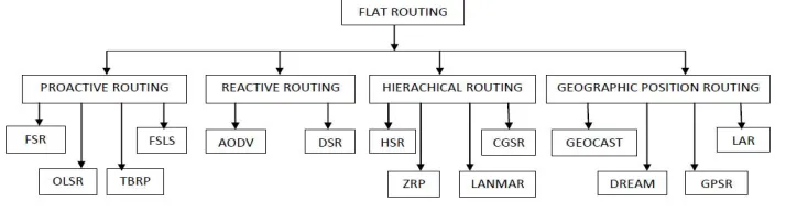
Routing protocols in MANET are divided into three categories: proactive, reactive and hybrid routing protocols.
Figure 1: Classification of Protocols
2.1PROACTIVEROUTING:
Proactive protocols provide fast response to topology changes by continuously monitoring topology changes and disseminating the related information as needed over the network like OLSR, FSR, TBRP, FSLS Protocols.
2.2 REACTIVE ROUTING:
Reactive routing protocols such as Ad hoc in demand distance vector (AODV), find the route only when there is data to be transmitted as a result, generate low control traffic and routing overhead. Dynamic Source routing protocol (DSR), each data packet contains complete routing information to reach its dissemination and each node uses caching technology to maintain route information.
COMPARISON OF DSR PROTOCOL IN
MOBILE AD-HOC NETWORK SIMULATED
WITH OPNET 14.5 BY VARYING
INTERNODE DISTANCE
Puneet Mittal1, Paramjeet Singh2 and Shaveta Rani3
1
Dept. of Computer Engg. Govt. Poly. College, Bathinda, Punjab, India
2,3
Volume 2, Issue 8, August 2013
Page 22
2.3 HIERACHICAL ROUTING:
Hybrid protocol could be derived from the two previous ones, containing the advantages of both the protocols like HSR, ZRP, LANMAR and CGSR.
2.4 GEOGRAPHIC POSITION ROUTING:
Geographic routing is a routing principle that relies on geographic position information. It is proposed for wireless networks and based on the idea that the source sends a message to the geographic location of the destination instead of using the network address. In this each node can determine its own location and that the source is aware of the location of the destination. With this information a message can be routed to the destination without knowledge of network topology or a prior route discovery like GEOCAST, DREAM, GPSR and LAR.
3. DYNAMIC SOURCE ROUTING (DSR)
DSR is also a reactive routing protocol. It uses the concept of source routing [2]. In source routing the sender knows all hop-by-hop routes to the destination. All the routes are stored in the route cache. When a node attempts to send a data packet to a destination it does not know the route. In DSR each node maintains a route cache with route entries which are continuously updated. The advantage of DRS is that no periodic routing packets are required. It is used to updates its route caches by finding new routes [3]. DSR has also the capability to handle unidirectional links. The sender of the packets selects and controls the route used for its own packets, which also supports features such as load balancing. All routes used are guaranteed to be free of loops as the sender can avoid duplicate hops in the selected routes [4]. The following sections introduce state machines that implement a simple DSR routing protocol without caching. There are basically 4 separate state machines to implement that each handles one of the following events [5] :
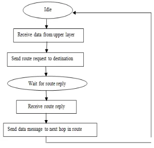
1.SENDING DATA: When a node wants to send data and data message is triggered as a send request then the next hop has be determined. A route request has to be broadcast to discover a route to the destination node. After receiving the route reply from the destination node the actual data message can be transmitted via the newly discovered.
Figure 2: Flow Chart of Sending activity diagram
2.INCOMING ROUTE REQUEST MESSAGE: When a route request message is received by a node, several tasks have to be done depending on the content of the received message. Firstly, it is checked whether the message was already processed earlier by this node. If yes, the request is simply discarded and no action is taken. If the route request is addressed to the receiving node, a route reply message has to be created and replied to the request’s sender. In all other cases the route request’s node list is extended by the own node ID and broadcasted to all neighboring nodes.
Volume 2, Issue 8, August 2013
Page 23
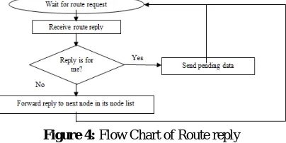
3.INCOMING ROUTE REPLY MESSAGE: In case a route reply message is received there are two cases: The receiving node is the destination of the message or it is an intermediate node on the route between sender and destination. If it is the destination node the data transmission that caused the route discovery can be accomplished. In case the route reply is received by an intermediate node, it is forwarded to the next node in the reply’s node list.
Figure 4: Flow Chart of Route reply
4.INCOMING DATA MESSAGE: If the data message is addressed to the receiving node (it is the last hop of the route) the payload can be handed to the upper layer to be processed by any application. The routing mechanism has finished. If not, the next hop is determined from the data message’s node list and the packet is forwarded to this node.
Figure 5: Flow Chart of Data message DSR contains 2 phases.
2.3.1 ROUTE DISCOVERY (FIND A PATH)
If sender node has in his route cache a route to the destination node, this route is immediately used. If not, the route discovery protocol is started:
Step 1 : sender node sends a route request packet by flooding the network. Each route request packet contains : route record, initiator address, request ID
Step 2 : if the route discovery is successful the initiating host receives a route reply packet.
Step 3 : when any host receives a route request packet, it processes the request accounting to the following steps. a)If <initiator address, request id> is found I this host then dicards the route request packet.
b)If this host’s address is already listed in the route record discard the route request packet.
c)If the target of the request matches this host’s address return a copy of this route in a route reply packet to the initiator.
d)Otherwise, append this host’s address to the route record and re-broadcast the request. After getting the route reply the sender send the data to the destination.
i. ROUTE MAINTENANCE
In DSR every node is responsible for confirming that the next hop in the source route receives the packet. Also each packet is only forwarded once by a node (hop-by-hop routing). If a packet can’t be received by a node, it is retransmitted up to some maximum number of times until a confirmation is received from the next hop. Only if retransmission results in a failure, a Route Error message is sent to the initiator that can remove that source route from its route cache. So the initiator can check his route cache for another route to the target. If there is no route in the cache, a route request packet is broadcasted.
Error Message
Volume 2, Issue 8, August 2013
Page 24
Step 1: if node C does not receive an acknowledgement form node D after some number of requests, it returns a Route Error to the initiator A.Step 2 : As soon as node receives the Route Error message, it deletes the broken-link-route from its cache. If A has another route to E, it sends the packet immediately using this new route.
Step 3 : Otherwise the initiator A is starting the Route Discovery process again.
ROUTE CACHE
DSR uses route cache, in this route cache source node contains all the paths which are discovered in the route discovery process. Route cache contains necessary information regarding in the network [6]. As the route cache store the discovered route, it can remove the unwanted route and overhead by eliminated the number of route request by considering the valid information and removing the invalid information. Route cache must be enough capable o store the all the paths which is in earlier route discovery process [7].
CACHE EXPIRY TIME
In the network when the nodes moves frequently, the connection between them are changes dynamically and cache hold this topology changes as the node interfaces with each other due to this it might be possible that a link in the cache which is not exist in the network. This information may create the many problems for sent packet. So we need a method which can delete the old entries from the cache after a certain interval of time called timeout, so chose this time out value is another critical issue. Here we have two method through which a timeout can be associated with each packet cache entry.
1. Static Timeout : When a link or path is added in the cache we add a predefined time T1 with this entry and when a reply comes through this link or path a different time T2 is associated in the remaining time.
2. Adaptive Timeout : This timeout associated with every link or path is dependent on the network condition.
4. VARIOUS PARAMETERS IN TRAFFIC LOADS
Table 1: Parameters Description
SR. NO.
PARAMETERS DESCRIPTION
1 Data dropped (Retry Threshold exceeded) (bits/Sec)
This statistic records the total amount of data that was received from the upper layer and then dropped by all WLAN nodes in the network due to repeatedly failed retransmission (i.e, exceeded the corresponding short retry or long retry threshold value).
2 Load (Bits/Sec) This statistic records the total amount of data submitted by the upper layer for transmission by the WLAN layer on all the nodes in the network.
3 Media Access Delay (Sec)
This statistic records the medium access delay experienced by the packets submitted for transmission on all WLAN interfaces in the network. This value is computed as the interval from the time the packets was inserted into the transmission queue until the time when the packet was sent to the physical layer for the first time.
4 Network load (Bits/sec)
This statistic is computed on a per-BSS basic. It represented the amount of data from the higher layer that was received, accepted and queued for transmission by the entire WLAN BSS.
All these parameters help us to evaluate the best Routing area between 825km, 1000km and 1300km. All the parameters that have taken play a very vital role to judge or evaluate the performance of the wireless network.
5.
SIMULATION
ENVIROMENT
Volume 2, Issue 8, August 2013
Page 25
Table 2: Simulation parameters
Figure 7: Environment Scenario of 20 Nodes in 825km
Figure 8: Environment Scenario of 20 Nodes in 1000km
Figure 9: Environment Scenario of 20 Nodes in 1300km
6.
RESULTS
AND
DISCUSSION
FTP LOAD
SIMULATION PARAMETER VALUE
Simulator OPNET MODELER 14.5
Area 825km, 1000km, 1300km
Network Size 20 nodes
Protocol DSR
Mobility Model Random Way Point
Traffic Type FTP
Simulation Time 900 (Sec)
Volume 2, Issue 8, August 2013
Page 26
6.1 Data dropped (retry threshold exceeded) (bits/sec)
Figure 10: Comparison of DSR Protocol for Data dropped (retry threshold exceeded) in FTP Load
In figure 15, X-axis denotes time in minutes and Y-axis is denotes data rate which is in bits/sec. It shows that the average peak value of Data dropped (retry threshold exceeded) is almost 6238.502924 bits/sec for 825km, 5110.081871 bits/sec for 1000km and 4973.660819 bits/sec for 1300km. After 15 minutes, it gradually drops to almost 3.259259259 bits/sec for 825km, 3.259259259 bits/sec for 1000km and 6.518518519 bits/sec for 1300km.
5.2 Load (bits/sec)
Figure 11: Comparison of DSR Protocol for Load in FTP Load
In figure 5, X-axis denotes time which is in minutes and Y-axis denotes data rate which is in bits/sec. It shows that the average peak value of load is almost 6238.502924 bits/sec for 825km, 5110.081871 bits/sec for 1000km and 4973.660819 bits/sec for 1300km. After 15 minutes, it gradually drops as time progress and reaches to almost 3.259259259 bits/sec for 825km, 6.518518519 bits/sec for 1000km and 6.5185189 bits/sec for 1300km.
5.3 Media Access Delay (Sec)
Figure 12: Comparison of DSR Protocol for Media Access Delay in FTP Load
Volume 2, Issue 8, August 2013
Page 27
5.4 Network Load (bits/sec)
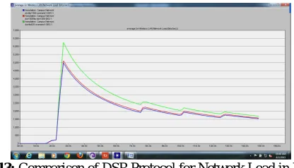
Figure 13: Comparison of DSR Protocol for Network Load in FTP Load
In figure 17, X-axis denotes time in minutes and Y-axis is denotes data rate which is in bits/sec. It shows that the average peak value of network load is almost 6238.502924 bits/sec for 825km, 5110.081871 bits/sec for 1000km and 4973.660819 bits/sec for 1300km. After 15 minutes, it gradually drops to almost 3.259259259 bits/sec for 825km, 6.518518519 bits/sec for 1000km and 6.518518519 bits/sec for 1300km.
Table 3 shows numeric values of various parameters taken into consideration for FTP load in DSR protocols. It gives the performance comparison of DSR protocols in terms of Data dropped (retry threshold exceeded), load, media access delay and network load for FTP load.
Table 3: Values of various parameters corresponding to distance area for FTP load in DSR protocol.
Parameters DSR PROTOCOL
825 km 1000km 1300km
Data dropped (retry
threshold exceeded) (bits/sec) 6238.502924 5110.081871 4973.660819
Load (bits/sec) 6238.502924 5110.081871 4973.660819
Media Access Delay (Sec) 0.146321001 0.092589429 0.077394898
Network Load (bits/sec) 6238.502924 5110.081871 4973.660819
7.
CONCLUSION
In this paper, we performed the comparison between 825km, 1000km and 1300km distance in DSR protocol with traffic load FTP in terms of Data dropped (retry threshold exceeded), Load, Media access delay and Network Load. The results are taken in tabular form as well as graphical form by using OPNET Simulator 14.5. The results show that which distance area is better for DSR protocol corresponding to FTP traffic load for some important parameters.
REFERENCES
[1.]Manoj Tolani and Rajan Mishra, “ Simulation based comparison of fixed ad hoc netwok and mobile ad hoc network by varying internode distance” , VSRD International journal of Electrial, Electronics & Communication engineering 2012.
[2.]Gurleen Kaur Walia and Charanjit Singh, “Node Density based performance Analysis of two Reactive Routing Protocols in Mobile Adhoc Networks”, UCOE Department, Punjabi University, Patiala.(2011).
[3.]Parulpreet Singh, Ekta Barkhodia and Gurleen Kaur Wali, “Evaluation of various Traffic loads in MANET with DSR routing protocol through use of OPNET Simulator”, Department of Electronics & Communication, LPU, Phagwara Punjab, India. (May 2012).
[4.]Gagangeet Singh Aujla, Sandeep Singh Kang, “Comprehensive Evaluation of AODV, DSR, GRP, OLSR and TORA Routing Protocols with Varying number of nodes and traffic applications over MANETs” Department of C.S.E, Chandigarh Engineering College, India. (April 2013).
[5.]Ad hoc and sensor networks, University of Paderborn, Computer Networks Group, 19 June 2007.
[6.]Kamal Kant Verma, “Analysis of caching strategy in dynamic source routing protocol for wireless mobile ad hoc network”, International journal of engineering & science research. July 2012.