694
Copyright © 2011-15. Vandana Publications. All Rights Reserved.
Volume-5, Issue-2, April-2015
International Journal of Engineering and Management Research
Page Number: 694-698
Adaptive Beamforming using CMA
Prachita P.Tribhuwan1 Dr. A.S.Bhalchandra2
1,2
Electronics &Telecommunication, Government College of Engineering, Aurangabad, INDIA
ABSTRACT
Smart antenna possess the capability of suppressing jamming signal, so they can improve signal to interference plus noise ratio (SINR). Smart antenna is most efficient leading innovation for maximum capacity and improved the quality and coverage. Smart antenna radiates not only narrow beam towards the desired users exploiting signal processing capability but also place nulls towards interferes thus optimizing signal quality and enhance capacity. In this paper Constant Modulus Algorithm(CMA)algorithm used for adaptive beamforming is presented. CMA in adaptive beam forming minimizes MSE. Therefore CMA is found more efficient algorithm to implement communication environment to enhance service quality and capacity.
Keywords---- Adaptive beamforming, Smart antenna,
antenna array, Constant Modulus Algorithm (CMA).
I.
INTRODUCTION
Basically antenna is a device used to transmit and receive the electromagnetic waves [1]. The term smart antenna refers to any antenna array terminated in sophisticated digital signal processor, which can adjust its own beam pattern in order to emphasize the signal of interest and to minimize signal of interest by changing the amplitude as well as phase.
In communication smart antenna steers the main beam in desired direction. It can produce low side lobe. Smart antenna helps in reducing co-channel interference. It also increases both capacity and range of communication system[2].
Smart antenna implementation strategy uses an adaptive antenna array whose outputs are combined through a set of complex weight which includes signal amplitude and phase adjustments to form a single output with beam steering. Beamforming is combination of radio signals from a set of small non-directional antenna. In
communication beamforming is used at point of signal source to reduce the interference and improve communication quality. Digital beamforming is combination between antenna technology and digital technology. Digital beamforming has three major components: antenna array, digital transceiver and digital signal processor. Beamforning is carried out by weighting of digital signal there by adjusting these amplitude and phase such that when added together they form desired beam. The combined relative amplitude ak and phase shift
θk for each antenna is called complex weight and is
represented by wkfor kthantenna [3][4].
In this paper adaptive beamforming scheme that is achieve by Constant Modulus Algorithm (CMA) to control weights adaptively to optimize signal to noise ratio (SINR) of the desired signal in look direction. CMA is kind of blind algorithm which doesn’t require training signals for its guidance therefore a lot of energy is conserved.
II.
ADAPTIVE BEAMFORMING
Adaptive beamforming is a technique in which an array of antenna exploited to achieve the maximum reception in specified direction (in presence of noise) while signal of the same frequency from the other directions are rejected. It is achieved by varying the weights of each elements (antenna) in the array. The signal received from an antenna is quadrature baseband signal with i and q components represent as complex vector (phaser) with real and imaginary part [3].
(1) jy(t) x(t) s(t) = + Where
s(t)=complex base band signal x(t)=i(t)=real part
695
Copyright © 2011-15. Vandana Publications. All Rights Reserved.
For beamforming complex baseband signal multiplied with complex weight to apply phase shift and amplitude scaling required for each antenna.
(2) ) sin( e k a k w k j θ = (3) ) k sin(θ k ja ) k cos(θ k a k
w = +
Where
wk= complex weight for kth antenna element
ak= relative amplitude of the weight
θk=phase shift of the weight
The complex weight wk
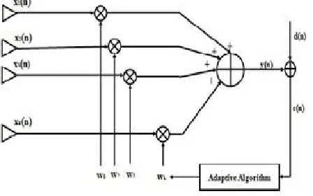
The x(n) signal received from an antenna with noise multiplied by weight vector w (amplitude and phase coefficient) which adjust the phase and amplitude of the incoming signal. This weighted signal is summed up and resulting in array output Y(n). Adaptive algorithm minimized error between desired signal d(n) and Y(n) which is generated by subtracting output of the beamformer from the reference signal. For the beamformation array output Y(n) at n time is given by linear combination of data at k and can be expressed as:
for the antenna elements are chosen carefully to give desired peaks and nulls in the radiation pattern weights are chosen to give radiation pattern that maximize the quality of the received signal. Figure 1 shows adaptive beamforming
(4) X(n) w Y(n) = × Where,
[
... wk]
1w w=
[
(n)]
k ....x (n)... 1 x x(n) =
The weight vector w is the complex vector. The process of weighting these complex weight adjusted their amplitudes and phases, so that when added together they form the desired beam. The adaptive beam former weights are computed to optimize the performance in terms of certain criterion.
The signal that arrives at antenna k, leads in phase with Kkdsinθ Where K = 2π/λ, an d λ is the waveleng th. This leads to the array propagation vector defined by:
( )
[
j k-1Kdsinθ]
...e jKdsinθ e 1 v =
The array factor is the response of the signal arriving from angle θ, Y(K,θ)and X(K,θ)are respectively the output and input of the beamforming array. Array factor is the function of passion of the antenna elements in array and weights.
If we consider Kand d being fixed parameters of the antenna,
Where k is the index of the antenna element
III. CONSTANT MODULUS ALGORITHM
The CMA method has been known as blind adaptive beamforming because it requires no knowledge about the signal except that transmitted signal waveform has constant envelope. Because of blind adaptive beamforming CMA does not require training set for its guidance therefore a lot of energy is conserved [5-7][10]. CMA is blind algorithm based on the idea to reduce the systems overhead and minimizing the total output energy.
As result number of bits for transmitting information is increased that leads to enhance capacity. This algorithm seeks for a signal with a constant magnitude that is modulus within the received data vector. Received data vector consist of desired signal,interference and noise[7]. It is gradient based algorithm that works on the theory that the existence of interference causes changes in amplitude of the transmitted signal, which otherwise has constant envelope (modulus) [8][9][11].
The weight is updated by equation
(6) X(n) error μ w
w = + × ×
µ=stepsize parameter The estimation error is Figure 1: Adaptive beamforming system
(5) jKkdsinθ e 1 k 0 k wk Factor(AF)
Array ∑
696
Copyright © 2011-15. Vandana Publications. All Rights Reserved.
) 7 (
Y(n) Y(n) Y(n)
e(n) = −
Y(n)= the array output after the nth
(
)
(
)
(
theta)
(8)jksin -e , ,...
theta -j2sin e theta -jsin e 1
k 1
w
× =iteration The algorithm of CMA is shown below
1. Define value of number of antennas i.e. k,and angle θ
2. Initialize weight vector [9]
3. X(n) is the total signal received from antenna with interference and system noise. (9) Noise n2
n1 x(n)
X(n) = + + +
4. Y(n) is array output which is obtained by total received signal multiplied with weight vector.
(10) X(n) w Y(n) = ×
5. w is the weight vector. Weight vector updating equation given by
(11) X(n) error μ w
w = + × ×
IV.
EXPERIMENTAL ANALYSIS
An adaptive digital beam forming using Constant Modulus Algorithm is implemented. Simulation is done using MATLAB R2013a 8.1.0.604. The input at each element of antenna array consists of sum of input signal (Figure. 2-complex MSK signal)and two interrupts in desired direction,including random noise signal as shown in Figure1.
697
Copyright © 2011-15. Vandana Publications. All Rights Reserved.
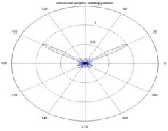
The simulation of radiation pattern using polar plots is performed with a linear array antenna. Best results are
available for µ=0.01 2
λ
d = ,
λ
2π
K= are fixed. K is the
wave vector that describe the phase variation.
698
Copyright © 2011-15. Vandana Publications. All Rights Reserved.
V.
CONCLUSION
In this paper adaptive beam forming, using CMA which is blind algorithm, is discussed. This algorithm for smart/ adaptive antenna array system, generates beam in desired (look) direction and nulls towards interferes.
Algorithm is tested for various values of wavelength, μ, and number of elements. Best possible results are with a combination of d=λ/2 and µ=0.01. Largerthe value of μ,faster the convergence but array system unstable/noisy.
Though, CMA is a blind algorithm, it is a better option to implement base station of mobile communication system to reduce system overhead, avoid interference, which enhancesthe communication performance,both in quality and capacity.
REFERENCES
[1] Balanis, Antenna Theory: analysis and design, (New Jersey: John Wiley & Sons, C.A (2005)).
[2] M.V.S.L. Srikanth, P.Santosh Kumar , S.Vijay Kumar , K.GowriprasadR.V.Ch.Sekhar Rao ,"Systematic
comparison of performance of different Adaptive beam forming Algorithms for Smart Antenna systems" , IOSR Journal of Electronics andCommunication Engineering Volume 9, Issue 1, Ver. V,Feb. 2014.
[3] Toby Haynes, "A Primer on Digital Beamforming" March 26, 1998.
[4] M. Ciaurriz, Y. Tawk, C. G. Christodoulou,J. Costantin, "Adaptive Beamforming for Random Planar Arrays", Antenas and Propagation society International Symposium IEEE July 2014.
[5] Thomas Ekeiner, Thomas Muller, Johann-Friedrich Luy, Frank Owens, "Implementation of a Smart Antenna System with an Improved NCMA Algorithm" Microwave Symposium Digest, IEEE,MTT-S Internation, vol. 3, June 2003
[6] Rumiko Yonezawa, Kazufumi Hirata, Tetsuo Kirimoto and Isamu Chiba, "Acombination of two adaptive algorithms SMI and CMA", Global Telecommunication conference, IEEE, vol.6,1998.
[7] M. Yasin, Pervez Akhtar, M. Junaid Khan, "CMA an Optimum Beamformer for a Smart Antenna System", International Journal of Computer Applications , Vol. 5– No.7, August 2010
[8] Balaji G. Hogade, Shrikant K. Bodhe, Nalam Priyanka Ratna, "Improved CMA: a beamforming algorithms for wireless System using smart antenna", International Journal of Computer Science and Mobile Applications,Vol.1 Issue. 5, November- 2013, pg. 84-96. [9] V.L.Bhavani.Maddirala, C.Subba Rao, "Analysis of Smart Antenna Beamformer characteristics using CMA and DMI", International Journal of Scientific & Engineering Research, Volume 3, Issue 7,July-2012.