Strojniški vestnik - Journal of Mechanical Engineering 53(2007)9, 524-540 U DK -UD C 621.914
Izvirni znanstveni prispevek - Original scientific paper (1.01)
Modelno podprt sistem za dinamično nastavljanje rezalnih
parametrov pri postopku frezanja
A Model-Based System for the Dynamic Adjustment o f Cutting Parameters during
a Milling Process
Franci Čuš - Uroš Župerl - Edvard Kiker (Fakulteta za strojništvo, Maribor)
V prispevku je predstavljen modelno podprt mehanizem vodenja, ki z obvladovanjem rezalnih sil zagotavlja stalno kakovost obdelane površine p ri postopku oblikovnega frezanja. Sistem z dinamično prilagajanje podajanja in vrtljajev obvladuje hrapavost površine ter rezalne sile na frezalu. Namen izdelave predlaganega mehanizma j e poiskati omejitve takšnega načina vodenja, ki s prilagajanjem rezalnih parametrov ohranja stalno rezalno silo. Modelno podprt sistem vodenja j e izdelan z razvojno metodo genetskega programiranja (GP). Za določitev empirične povezave med kakovostjo površine in rezalno silo j e izdelan načrt preizkusov. Pri vnaprej definirani globini rezanja je preizkusno raziskan vpliv obdelovalnega
materiala in rezalnih parametrov (podajanje, globina rezanja) na omenjeno povezavo.
Razvojna metoda GP je uporabljena za izpeljavo izkustvenih povezav med kakovostjo površine in rezalno silo pri obdelavi jekla. Te povezave se nato uporabijo pri izdelavi modelno podprtega sistema za dinamično nastavljanje rezalnih parametrov (SDNRP), v katerem se s krmiljenjem rezalnih sil dviga zahtevana kakovost površine. Rezultati zagotovijo načine za povečanje učinkovitosti postopka z izboljšanjem kakovosti površine, zmanjšanjem posledic spremenljivosti postopka in zmanjšanjem stroškov napak pri opravilih
končne obdelave.
© 2007 Strojniški vestnik. Vse pravice pridržane.
(Ključne besede: končno frezanje, rezilni parametri, genetsko programiranje, sistemi vodenja, modelno podprti sistemi)
This paper presents a model-based mechanism o f control ensuring the constant quality o f the surface finish by controlling the cutting forces during the end-milling process. Using the dynamic adaptation o f feeding and speed the system controls the surface roughness and the cutting forces on the milling cutter. The purpose o f developing such a mechanism is to fin d the limitations o f this type o f control, which maintains a constant cutting force by adapting the cutting parameters. This model-based system o f control was developed by the evolutionary method o f genetic programming (GP). A drawing o f experiments was made in order to determine the empirical correlations between the quality o f the surface finish and the cutting force. With the depth o f cutting defined in advance the influence o f the workpiece material and cutting parameters (feeding, cutting depth) on the abovementioned correlation has been experimentally researched.
The evolution genetic programming method (GP) was applied to derive an empirical relationship fo r the surface finish and the cutting force values fo r steel materials. These relationships were applied to develop the proposed evolution simulation model in which the cutting force is adjusted to improve the required surface quality fo r the end-milling process. The results provide a means fo r greater efficiency by improving the surface quality, minimizing the effect o f the process variability and reducing the error cost during finishing operations.
© 2007 Journal o f M echanical Engineering. All rights reserved.
(Keywords: end-milling, cutting parameters, genetic programming, model-based control)
0 UVOD 0 INTRODUCTION
Vodenje postopkov frezanja je trenutno v The control o f milling processes is currently
koristi, povezanih z avtomatizacijo odrezovanja [1], D eset odstotna dodatna investicija v izboljšanje zm ogljivosti sistema vodenja povzroči 10-odstotno povečanje storilnosti frezanja. To pomeni 1000- k ratn o povrnitev investicije m ed dobro trajanja stroja [1], Postopki frezanja so zanimivi z vidika v o d en ja zaradi težav, kakršne so nelinearnosti, časovno spremenljivi parametri in obraba orodja ([2 ] in [3]). N ed av n o so m nogi ra zisk o v alci preučevali ta problem [4], Tehnike vodenja, ki so iz d e la n e za p ostopke obdelave, tradicionalno zahtevajo neki način prilagajanja parametrov ([1] in [5]). Rešitev tega problema je prilagajajoče se vodenje. Prilagajajoče se sisteme vodenja vpeljeta v p o s to p e k o d re z o v a n ja S tute in G o etz [6]. N a jp o g o s te je u p o rab ljen a sistem a sta M RAC (m odelno referenčno prilagajajoče se vodenje) [7] in STR (samonastavljivo krmiljenje) [8], MRAC izh aja iz teorije prilagajajočega se vodenja in je p o g o s to u p o ra b lje n za ra d i sv o je g ro b o sti in zm ožnosti odpravljanja motenj. Izdelane so številne oblike sistema MRAC ([9] in [10]). Draga rešitev teg a problem a so inteligentne nadzorne strategije ([11] in [12]). Pomanjkljivost inteligentnih strategij j e v te m , da ra č u n a n je n e v ro n sk e m reže in genetskega algoritma terja nekaj časa, kar omejuje odzivnost inteligentnega sistema vodenja.
Kljub začetnim razvojnim težavam je opaziti usmeritev nadgrajevanja računalniško krmiljenih (RK) frezalnih strojev s sodobnimi prilagojenimi sistemi. Z a ra d i p o treb e po po v ečev an ju storilnosti, zmanjševanju stroškov dela, preprečevanju delovnih nezgod, izboljšanju kakovosti obdelave in zmanjšanju č lo v e šk e g a v p liv a na p o sto p ek se usm eritev avtomatizacije postopka frezanja še stopnjuje.
Z a uspešno avtom atizacijo, pri kateri se postopek odvija brez človekovega posredovanja, je treba neprekinjeno spremljati postopek obdelave. To se najpogosteje izvede z meijenjem rezalnih sil, k e r te vsebujejo največ informacij o postopku in stan ju orodja. Z analizo značilke rezalne sile je m ogoče oceniti spremembe v kakovosti obdelane površine [13].
N ašteta dejstva so izhodišča za izdelavo m o d e ln o p o d p rte g a siste m a za d in am ičn o n astav ljan je in optim iranje rezalnih param etrov (SD N R P). To je prilagajajoči se sistem vodenja, ki z neprekinjenim dinamičnim nastavljanjem rezalnih param etrov nadzoruje rezalno silo in ohranja stalno h ra p a v o st obdelane površine m ed obdelavo. V okviru raziskave je izdelan simulacijski model, ki
econom ic benefits associated w ith autom ated machining [1]. An additional investment of 10% to increase the capabilities o f the control system gives a 10% increase in p ro ductivity for the m illing operations. Over the lifetime o f a machine, this results in a return on investment o f 1000 times [1]. Milling processes are interesting from a control perspective due to difficulties such as system nonlinearities, time- varying parameters and tool wear ([2] and [3]). Various investigations have looked at this problem in the recent past [4], Control techniques that have been developed for machining traditionally require some form of parameter adaptation ([1] and [5]). One solution to this problem is adaptive control. An adaptive control system is introduced in the cutting process by Stute and Goetz [6]. The most frequently used systems are MRAC (Model Reference Adaptive Control) [7] and STR (Self Tuning Regulations) [8]. MRAC, developed from adaptive control theory, is widely used because o f its robustness and disturbance-rejection capability. Numerous forms o f the MRAC system have been developed ([9] and [10]). Another solution to this problem is a number o f intelligent control strategies ([11] and [12]). The drawback o f intelligent strategies is that neural-network- and genetic-algorithm-based calculations take time, which limits the response of the intelligent control system.
In spite o f the initial difficulties in the developm ent, a trend tow ards equipping CNC milling machines with modem adaptive systems is clear. Because o f the requirements for increased productivity, reduced working costs, the prevention o f accidents, improved quality o f the milling and a reduced human influence on the process the trend towards automation o f the milling process increases.
For effective automation, where the process takes place without human interference, continuous monitoring o f the milling process is necessary. Most frequently, this is realised by measuring the cutting forces, because they contain the most information about the process and the tool’s condition. By analyzing the cutting force’s characteristics it is possible to assess the changes o f the quality of the surface finish [13],
se uporablja za testiranje stabilnosti in usklajevanje param etrov prilagajajočega se sistem a SDNRP - Poglavje 5. SDNRP sprem inja svoje odzive kot o d g o v o r na m otnje in sprem em be v dinam iki postopka odrezovanja.
Po izvedenih simulacijah je sistem SDNRP popolnom a pripravljen in usklajen za uporabo v dejanskem postopku frezanja. Simulacijska shema predlaganega sistema je predstavljena na sliki 3.
1 MODELNO PODPRTO VODENJE POSTOPKA FREZANJA
Na modelu temelječ sistem vodenja vsebuje krm ilnik, ki lahko prilagaja svoje delovanje kot o d g o v o r na sprem em be dinam ike p o sto p k a in motnje. Če ostaja rezalna sila nespremenjena med postopkom obdelave, potem tudi kakovost površine ostane nespremenljiva. V prejšnjih raziskavah [14] se p rid o b i iz h a ja jo č a re z a ln a sila s p o m o čjo K istlerjevega m erilnika, ki določi tri pravokotne
kom ponente dinam ičnih sil: F , F, F . Te sile so
izm erjene sproti z uporabo program ske oprem e Lab View. Izmeijeni signali rezalnih sil se uporabijo v modelnem krmilniku pri uravnavanju rezalne sile. Glavni cilj te raziskave je izdelati na genetskem m odelu tem elječ sistem vodenja, ki lahko reši takšne zahtevne problem e vodenja odrezovanja. C ilj p re d la g a n e g a sistem a v o d en ja j e k rm iliti param etre postopka frezanja, to so podajanje in v rtiln a frekvenca vretena ter ohranjati rezalno h itr o s t n e s p re m e n je n o , da se s p ro ti d o se ž e zahtevana vrednost kakovosti površine. Uporabimo f re z a ln i stro j H e lle r B EA 01 v p o v e z a v i s krm ilnikom podaj alnega pogona.
2 RK PODAJALNI SERVO-SISTEM STROJA
Preizkusi so izvedeni na RK frezalnem stroju Heller. To je štiriosni obdelovalni stroj, ki dopušča tri premike vzdolž osi X, Y in Z ter vrtenje palete v vodoravni ravnini. Vgrajeno je računalniško krmilje FA G O R 8040-M . Pogon podajalnih osi je prek krogličnih vodil izveden z izmeničnimi električnimi s e rv o m o to rji, ki so sin h ro n iz ira n i s tra jn im i magneti. Oznaka servopogona je: Heller S 044/82
8 -A 2 0 -2 2 2 0 -0 0 1 /0 2 C . B lo k o v n o sh em o
(sim u lacijsk i m odel) podajalnega servosistem a p rik a z u je slik a 2. Š tev ilčn e v re d n o sti staln ic blokovne sheme so prikazane v preglednici 1. N a v h o d n e m k a n a lu siste m a p rid e do č a so v n e
research a simulation model for testing stability and harm onizing param eters o f the adaptive system (SDNRP), Section 5, has been developed. The SDNRP changes its reactions in response to disturbances and changes in the dynamics of the cutting process.
A fter the execution o f the simulations the system (SDNRP) is fully ready and harmonized for use in a real milling process. The simulation diagram o f the proposed system is presented in Figure 3.
1 MODEL-BASED MILLING-PROCESS CONTROL
A model-based control system is a controller that can modify its behaviour in response to a change in the dynamics o f the process and the disturbances. If the cutting force is maintained constant during the process o f machining, then the surface finish also remains stable. In previous research work [14] the resultant cutting force is obtained using a Kistler force tran sd u cer, w h ich p ro v id es th ree orthogonal
components o f the dynamics forces, Fx, F , Fz, and
these forces were measured online using Lab View software. These measured cutting force signals are used in a model controller to regulate the cutting force. The main objective o f this research is to develop a genetic model-based control system that can solve such difficult m achining control problem s. The objective o f the proposed control system is to regulate the milling process’ operation parameters, such as the feed rate and the spindle speed, and maintain the constant cutting force to achieve online the required value o f the surface finish. A Heller BEA01 milling machine was used in connection with a feed drive controller.
2 CNC MACHINE FEED DRIVE SYSTEM
The tests were carried out on the Heller CNC milling machine. This is a four-axes machine tool
allowing three translations along the X, Y and Z axes
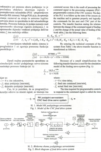
z a k a sn itv e pri prenosu ukaza podajanja: to je p o s le d ic a o b d e la v e u k a z n e g a sig n a la v postopkovnem računalniku (PLK - programljivem krm ilju RK sistema). Naloga PLK-ja je, da spremlja s ta n je z a z n av al na stroju in u strezno logično ustvaija ukaze za uporabnika in del računalniškega krm ilja. Prenosna funkcija, ki podaja razmerje med sp re m e m b o u k azn eg a sig n ala p o d a ja n ja f c in sprem em bo dejanske vrednosti podajanja delovne m ize / ' im a naslednjo obliko:
fai*) Ki
command occurs: this is the result o f processing the command signal in the processing computer (PLC- programmable controls o f the CNC system). The duty of the PLC is to follow up the state o f the sensors on the machine and to generate properly and logically the commands for the user and CNC part o f the controls. The transfer function stating the relation between the change o f the command signal of feeding
f c and the change of the actual value o f feeding of the
work table /j has the following form:
■Ki p . K t . e ~ s t '
(
1
). f c(s ) J e -La -si + J e(Rra + Kh ■Kip)-s2 + Kt {Kp ■ Kjp + K b)-s + K j -Kl -KjpZ vstavljanjem tehničnih stalnic sistema iz By entering the technical constants o f the
p r e g le d n ic e 1 se z g o rn ja p re n o sn a fu n k c ija system from Table 1 the above transfer function is
preoblikuje v: transformed as follows:
f j s ) 497000 e~0 08s_______
f c(s) ~ (s + 14,0) + (s2 +1555 +35500)
Zaradi majhne poenostavite uporabimo za B ecause o f a sm all sim p lificatio n the
s im u la c ijsk i m odel podajalnega servo-sistem a following transfer function is used for the simulation
naslednjo prenosno funkcijo (sl. 1): model of the feeding servo-system (Fig. 1):
f a 14,0-e-0’081
f c (5 + 14,0) (3),
kjer so:
- 1 = 8 s: čas zakasnitve,
- f : ukaz podajanja [mm/min], - / : dejansko podajanje [mm/min].
Č as, ki je potreben, da se program ljivo krm ilje odzove na ukazni signal, se im enuje čas
where:
- t = 8 s: time delay,
- f \ feed rate command [mm/min],
- f \ actual feed rate [mm/min].
The time required for programmable controls to respond to the command signal is called the time
RK podajalni servosistem CNC feed drive servo system
Sl. 1. Model RK podajalnega servosistema
Fig. 1. Model o f the CNC feed drive system
Ojačanje merilnega člena el.
Ojačanje toka
Sl. 2. Blokovna shema podajalnega servosistema
Preglednica 1. Heller Ltd. Tehnični podatki podajalnega servosistema
Table 1. Heller Ltd. Technical data fo r the feed drive system
Param eter Opis /Description Vrednost/Value
fc
želeno podajanje (ukaz podajanja) [mm/min]
desired feed rate (Feed rate comm and) [mm/minl -fa
dejansko podajanje [mm/min]
actual feed rate [mm/min]
-C0c ukaz kotne hitrosti [rad/min]
angular velocity com m and [rad/min]
-Ki ojačanje I-krm ilnika vrtilne hitrosti [V/(rad s)]
velocity integral gain [V/(rad s)l 8 ,2
Kp velocity proportional gain [V/(rad s)]faktor ojačanja m erilnega člena vrtilne frekvence [V/(rad s)] 0,4944 Vic ukaz toka [f]
current com m and [f|
-Kh faktor ojačanja - m erilnik električnega toka [f/A]
current feedback gain [f/A] 0,007
R r a upor rotorskega na vitja [Q]
armature coil resistance [Q] 0,15
K, stalnica vrtilnega m om enta [N f m/A]
torque constant [N f m /A] 0,165
Tm stalnica vrtilnega m om enta elektrom otorja [N f m]
electro m otor torque gain [N f m]
-Je ustrezna vztrajnost podajalnega pogona [N f m s] equivalent feed drive inertia [N f m s] 0,0146
GJa dejanska vrtilna frekvenca gredi m otorja [rad/min]
actual velocity [rad/min]
-k f količnik ojačanja - vrtilna frekvenca [(rad/s)/(mm /min)]
angular velocity gain [(rad/s)/(mm /min)] 0,105
KFz ojačanje - podajanje [(mm/min )/(rad/s)]
feed rate gain [(m m /m in )/(rad/s)] 1,04
V if dejanski tok - povratna zveza [f]
feedback current [f]
-Kip proporcionalno ojačanje krm ilnika toka
current proportional gain 7,5429
La induktivnost rotorskega navitja [mH]
armature coil inductance [mH] 1 , 2 0
Id dejanski električni tok [A]
actual current [A]
-Kb stalnica EM F - m erilni člen hitrosti [V/(rad/s)]
back EMF constant - velocity m easuring block [V/(rad/s)] 0,38
Td vrtilni m om ent m otnje [N f m]
disturbance torque [ N f m ]
-zak asn itv e. G lavni nam en SD N RP je ustvariti
v rsto ukazov p o d ajan ja f c in v rtiln e frekvence
n te r s tem k rm iliti vrednost rezaln e sile, tako
d a b o ta o h r a n ja la ž e le n o s ta ln o k a k o v o s t p o v ršin e.
3 GP-MODELI REZALNIH VELIČIN
Učenje modelov rezalnih veličin je izvedeno z izkustvenimi rezultati, ki so podani v prejšnjih
o f the delay. The principal aim o f the SDNRP is to generate a series o f commands for feeding^ and the
speed o f rotating nc and, thus, to regulate the values
o f the cutting force so that the latter will maintain the desired constant quality o f the surface.
3 GP-BASED MODELS OF THE CUTTING QUANTITIES
raziskavah ([15] in [16]). Namen modelov je podati
fu n k c io n a ln e o d v isn o sti m ed v p liv n im i
o d re z o v a ln im i p a ra m e tri: v rtiln o frek v en co , hrapavostjo površine in rezalno silo. Za določitev m edsebojnih razmerij m ed vrtilno frekvenco in p o d ajan jem ter rezalno silo in hrapavostjo je u p o ra b lje n a m etoda genetskega program iranja (G P). Pri GP je rezultat m atem atična form ula, sestavljena iz nabora predpisanih opravil. Omenjena m etoda bo predstavljena v nadaljevanju.
3.1 Modeliranje GP
V sim ulacijah se uporabijo GP modeli, ker j i h j e v sim u lacijsk em p a k e tu S im u lin k laže p r e o b lik o v a ti v b lo k o v n i z ap is. Z a izd elav o v s a k e g a g e n e tsk e g a m o d e la se u p o ra b i 185 p reizk u sn ih podatkov. Merilni podatek vsebuje v re d n o st napovedane (m odelirane) veličine in p r ip a d a j o č e v p liv n e p a r a m e tr e (re z a ln e p a ra m e tre ). N a p o d la g i v h o d n ih in m erilnih p o d a tk o v te r ob iz b ran em n a b o ru raču n sk ih opravil se u stv arijo m odeli: K I, K2, K3, K4, K 5= K 6. B lokovne shem e najbolj prilagojenih m o d elo v so p o dane v p o g lav ju 3.2. Izbran je n a b o r n a s le d n jih osnovnih raču n sk ih opravil
d F = {+, -, *, uv, ln} in razlogov {2, 2, 3, 2}.
M n o ž ic a om ejil ( d F ) j e p o d an a ob blo k o v n i sh em i p o sa m e z n e g a m odela. M nožico omejil o b i č a j n o s e s ta v lja jo v h o d n i p o d a tk i in sp rem en ljiv k e sistem a.
Z a določitev modela odrezovanja (K4) je
izbrana velikost populacije organizmov M = 1500
in število generacij G = 100. V drugih modelih je
M = 850 in G = 100. Uporabljene so standardna
g e n e ts k a o p ra v ila re p ro d u k c ije , k riž a n ja in
m utacije. V erjetnost reprodukcije je p r = 0,15,
k rižan ja p c = 0,5 in m utacije p m = 0,1. Razvoj
m odela se ustavi, k o je doseženo predpisano število generacij ali ko je prilagojenost organizma večja od 97 odstotkov.
3.2 Izpeljani GP modeli rezalnih veličin
Pred vsako obdelavo je znana zahtevana
kakovost obdelane površine Ra. Spodnja enačba
podaja rezalno silo Fd, s katero se doseže in ohranja
z a h te v a n a h ra p a v o st p o v ršin e . Z a m o d eln i
param eter Fd je po metodi GP izoblikovan naslednji
obrazec:
stated in previous researches ([15] and [16]). The purpose o f models is to define functional dependences between the influencing cutting parameters: spindle speed, surface roughness and cutting force. The genetic pro g ram m in g (G P) m ethod is used for the determination of mutual relations between the rotating speed and feeding and between cutting force and roughness. In case of GP the result is the mathematical formula consisting o f a series o f prescribed operations. That method will be presented hereinafter.
3.1 GP Modelling
GP models are used in simulations because, in the simulation package Simulink, they can be more easily transformed into the block recording. A total o f 185 pieces o f experim ental data are used to develop each genetic model. The experimental datum contains the value o f the predicted (modelled) quantity and the appurtenant influencing parameters (cutting parameters). On the basis o f the input and the experimental data and with a selected series of calculation operations the models, K l, K2, K3, K4, K5 = K6, are generated. The block diagrams of the most adapted models are given in Section 4.2. The series o f the following basic calculation operations
dF= {+, -, *, uv, In} and arguments { 2 ,2 ,3 ,2}is
selected. The set o f terminals ( d^) is given in addition to the block diagram o f the individual model. Usually, the set o f terminals consists of input data and the variables o f the system.
The size o f the population o f organisms,
M = 1500, and the number o f generations, G = 100,
were selected for the determination o f the model of
cutting (K4). On other models M= 850 and G = 100.
The standard genetic operations o f reproductions, crossover and mutation were used. The reproduction
probability, pr, was 0.15, the crossover probability,/?.,
was 0.5 and the mutation probability,/^, was 0.1. The developm ent o f the model is stopped when the prescribed number o f generations is reached or when the fitness o f the organism is greater than 97 %.
3.2 Derived GP Models of Cutting Quantities
Prior to any machining the required quality
o f the surface finish Ra is set. The equation below
gives the cutting force Fd with which the required
surface roughness is reached and maintained. For
the model parameter Fd the following formula was
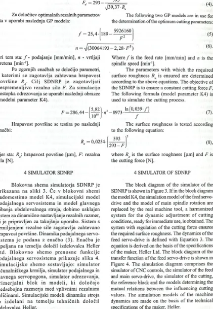
Fd = 293 — 593
Za določitev optimalnih rezalnih parametrov sta v uporabi naslednja GP modela:
>/39,37 Ra
The following two GP models are in use for the determination o f the optimum cutting parameters:
/ = 25,4- 189 —5926160
n = ^/(3°064193 - 2 , 2 8F 3)
(5)
(6) .
Pri tem sta: / - podajanje [mm/min], n - vrtljaji
vretena [m in 1].
Po zgornjih enačbah se določijo parametri, s k a te rim i se z a g o ta v lja zah tev an a h ra p a v o st p o v rš in e R a. C ilj SD N R P j e z a g o ta v lja ti n e sp re m e n ljiv o re z a ln o silo F. Z a sim u lacijo postopka odrezovanja se uporabi naslednji obrazec (modelni param eter K4).
W here / is the feed rate [mm/min] and n is the
spindle speed [m in 1].
The param eters w ith w hich the required
surface roughness Ra is ensured are determined
according to the above equations. The objective of
the SDNRP is to ensure a constant cutting force F.
The following form ula (model param eter K4) is used to simulate the cutting process.
F = 286,44-
[
5,
82]
10"
n —8973 In (0 ,0 3 9 -/)
7
(7).
H rapavost površine se testira po naslednji enačbi:
Ra = 0,0254 •
The surface roughness is tested according to the following equation:
>2 593
293 - F (8),
kjer sta: Rg: hrapavost površine [pm], F: rezalna where Ra is the surface roughness [pm] and F is
sila [N]. the cutting force [N].
4 SIMULATOR SDNRP
B lo k o v n a shem a sim ulatorja SD N R P je p r ik a z a n a n a s lik i 3. Če v b lo k o v n i sh em i n a d o m e stim o m o d e l K 4, sim u la c ijs k i m o d el p o d a ja ln e g a se rv o siste m a in m o d e l g la v n eg a gibanja o b d elo v aln eg a stroja, dobim o usklajen sistem za dinam ično nastavljanje rezalnih razmer, ki je pripravljen za takojšnjo uporabo. Sistem s k rm iljen jem rezaln e sile zag otavlja zahtevano hrapavost površine. D inam ika podajalnega servo- s is te m a j e p o d a n a z en ačb o (3 ). E n a č b a je izpeljana n a tem elju določil izdelovalca H eller L td . B lo k o v n o sh e m o p r e n o s n e f u n k c ije p o d a ja ln e g a se rv o s is te m a p rik a z u je s lik a 4. S im u la c ijs k o sh e m o s e s ta v lja jo : s im u la to r računalniškega krm ilja, sim ulator podajalnega in g lav n eg a serv o p o g o n a, sim ulator o drezovanja, p r i m e r j a l n i b lo k in m o d e li, k i d o lo č a jo m ed seb o jn a razm erja m ed vplivnim i rezalnim i veličinam i. Sim ulacijski m odeli dinam ike stroja so iz d e la n i n a te m e lju te h n ič n ih d o lo č il izdelovalca Heller.
4 SIMULATOR OF SDNRP
Sl. 3. Blokovna shema sistema za dinamično nastavljanje rezalnih parametrov
Fig. 3. Block diagram o f the system fo r dynamic adjusting o f the cutting parameters
Prenosna Časovni premik funkcija prenosa Transfer Transfertime
function delay
\
* 14
%
) *
s+14
- C O
fa
K
—W
-0,5
593 ►
293 --- ^ +
SI. 4. Prenosna funkcija podajalnega
servosistema
Fig. 4. Feed-drive servo-system transfer
function
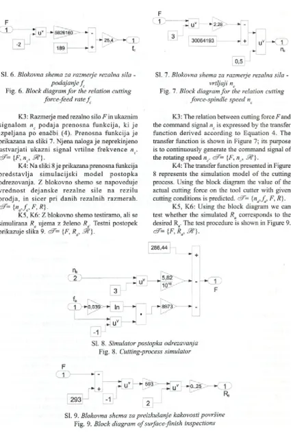
Sl. 5. Blokovna shema za razmerje hrapavost
površine - rezalna sila
Fig. 5. Block diagram fo r the relation surface
roughness-cutting force
V n a d a ljev an ju so podrobno p red stav ljen e prenosne funkcije posameznih elementov SDNRP in pretok signalov med njimi.
K I: Slika 5 prikazuje prenosno funkcijo, ki podaja odvisnost med želeno hrapavostjo površine
in pripadajočo rezalno silo Fd. Prenosna funkcija
je podana v obliki blokovne sheme. Modeliranje je iz v e d e n o s sta n d a rd n o z b irk o b lo k o v v program skem paketu M atlab 6.5. Uporabljena je
m nožica omejil: d?= F p J?} . 9 t- realna števila
na obm očju od -10 do 10.
K2: Prenosna funkcija za napovedovanje optimalnega podajanja^ je izpeljana po enačbi (5). Slika
6 prikazuje njeno blokovno shemo. {f jc, m
-In the following the transfer functions o f the individual elements o f the SDNRP and the flow o f signals between them are presented in detail.
K1 : Figure 5 shows the transfer function defining the d ep en d en ce b etw een the d e sire d surface
roughness and the appurtenant cutting force Fd. The
transfer function is given in the form o f block diagrams. Modelling is effected with the standard set o f blocks in the programme package Matlab 6.5.
The set o f terminals <FF= {Ra, F^ J ? }is used, where
J f i s a real number in the interval from -10 to 10. K2: Transfer function for the prediction of the optimum feeding^ is derived according to Equation
F
Sl. 6. Blokovna shema za razmerje rezalna sila
-podajanje f
Fig. 6. Block diagram fo r the relation cutting
force-feed rate f
SI. 7. Blokovna shema za razmerje rezalna sila
-vrtljaji nc
Fig. 7. Block diagram fo r the relation cutting
force-spindle speed nc
K3 : Razmeij e med rezalno silo F in ukaznim
sig n a lo m nc p o d a ja p re n o sn a fu n k c ija , ki je iz p e lja n a po enačbi (4). P ren o sn a fu n k c ija je prikazana na sliki 7. N jena naloga je neprekinjeno u s tv a rja ti u k a z n i sig n a l v rtiln e fre k v e n c e n .
ć7-={F,nc,9 ? } .
K4: N a sliki 8 je prikazana prenosna funkcija p r e d s ta v lja s im u la c ijs k i m o d e l p o s to p k a odrezovanja. Z blokovno shemo se napoveduje v re d n o s t d e ja n s k e re z a ln e s ile n a re z ilu o ro d ja , in sic e r p ri d an ih re z a ln ih razm erah .
cJ7={na, f , F , R } .
K5, K6: Z blokovno shemo testiramo, ali se
simulirana Ra ujema z želeno Ra. Testni postopek
prikazuje slika 9. dZ= {F, Ra, 9 t ) .
K3 : The relation between cutting force F and
the command signal nc is expressed by the transfer
function derived according to E quation 4. The transfer function is shown in Figure 7; its purpose is to continuously generate the command signal o f
the rotating speed nc. dZ= {F, nc, &}■
K4: The transfer function presented in Figure 8 represents the simulation model o f the cutting process. Using the block diagram the value o f the actual cutting force on the tool cutter with given
cutting conditions is predicted. dF= {na, f a, F, R).
K5, K6: Using the block diagram we can
test w hether the simulated Ra corresponds to the
desired Ra. The test procedure is shown in Figure 9. dZ= {F, Ra, & } .
SI. 8. Simulator postopka odrezavanja
Fig. 8. Cutting-process simulator
SI. 9. Blokovna shema za preizkušanje kakovosti površine
Nemodelirana dinamika postopka Unmodeled process
dynamics
Osciloskop Osciloscop
w
— * 0 ...'*■
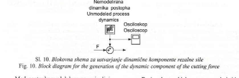
Sl. 10. Blokovna shema za ustvarjanje dinamične komponente rezalne sile
Fig. 10. Block diagram fo r the generation o f the dynamic component o f the cutting force
M ed postopkom obdelave se pojavljajo n e z a ž e le n e v ib ra c ije in m o tn je . V z ro k i so: nehomogenost osnovnega materiala, obraba orodja, poškodbe orodja, napake v vodilih in ležajih stroja itn. Z vključevanjem naključnih motenj v simulacijo se te stirata stabilnost in grobost predlaganega siste m a vodenja. V sim ulacijskem m odelu se u s tv a rja n e m o d e lira n o d in am ik o p o sto p k a z n a k lju č n im i v re d n o stm i, ki se u je m a jo z oscilacijami izmerjenih rezalnih sil. Shema na sliki 10 sim u lira n em o d eliran o d inam iko stro ja in postopka.
M ed simulacijo se na diagramih nadzorne konzole izrisujejo naslednje veličine:
• dejanska hrapavost površine,
• hrapavost površine pri upoštevani dinam iki
stroja,
• naj večja rezalna sila,
• n a jv e č ja re z a ln a s ila z d in a m ič n o
kom ponento,
• dejansko podajanje,
• dejanski vrtljaji vretena.
5 POTEK IZVEDBE SIMULACIJE SDNRP
Z m o g ljiv o s t S D N R P j e te s tir a n a s
s im u la c ija m i. U p o ra b lje n j e M a tla b o v
s im u la c ijs k i p a k e t S im u lin k . S im u la c ijo
sprožim o z nastavitvijo referenčne vrednosti Ra,
nato se po m odelu K I napove želena rezalna sila
Fd Ko je znana sila Fd, se po m odelu K2 in K3 v
trenutku izračunajo vrednosti/^ in ny D inam ični
o d ziv serv o sistem a na signal f c je sim uliran z
blokovno shem o, k ije podana na sliki 2. Prenosni f u n k c iji s e rv o s is te m o v u s tv a rja ta d e ja n s k o p o dajanje f in vrtljaje na, tako d a j e po m odelu K 4 n a p o v e d a n a re z a ln a s ila nesprem enljiva. S im u lira n a R a se d o lo či s p ren o sn o fu n k cijo m odela K5.
During the machining process undesirable vibrations and disturbances occur. They are caused by inhomogeneity o f the base material, tool wear, tool damage, defects in guides and bearings o f the machine, etc. By introducing the random disturbances into the simulation the stability and robustness o f the proposed control system can be tested. In the simulation model the unmodeled dynamics of the process is generated by random values corresponding to the oscillations o f the measured cutting forces. The diagram in Figure 10 simulates the unmodeled dynamics o f the machine and the process.
During the simulation the following values are drawn in the diagrams o f the control console:
• Actual surface roughness,
• Surface roughness considering the machine-tool
dynamics,
• Maximum cutting force,
• M axim um cutting force w ith the dynam ic
component,
• Actual feeding,
• Actual spindle speed.
5 THE REALIZATION COURSE OF THE SDNRP SIMULATION
The SDNRP capacity was tested by simulations. For this we used the M atlab simulation package Simulink. The simulation is initiated by the adjustment
o f the reference value R j afterwards the desired cutting
force Fd is predicted according to the model K1. When
the force Fd is known, the values F and nc are calculated
within a moment according to the model K2 and K3. The dynamic response o f the servo-system to the signal
f is simulated by the block diagram given in Figure 2.
The two transfer functions of the servo-systems generate
the actual feeding^ and speed na, so that the cutting
6 PRIMER IZVEDENE SIMULACIJE SDNRP
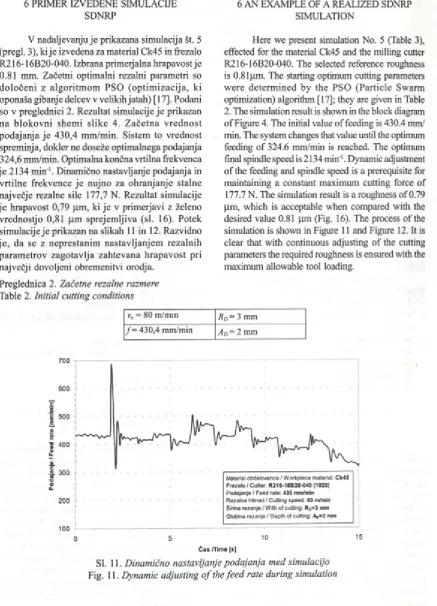
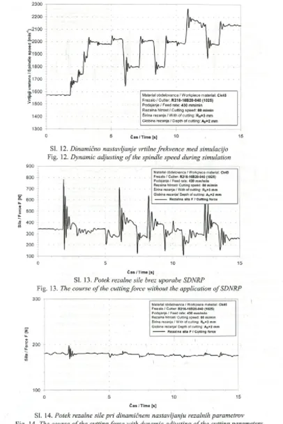
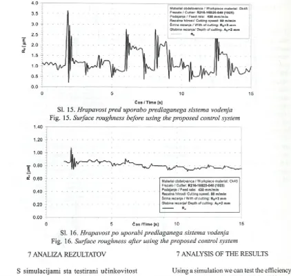
V nadaljevanju je prikazana simulacija št. 5 (pregi. 3), k ije izvedena za material Ck45 in frezalo R216-16B20-040. Izbrana primerjalna hrapavost je 0.81 mm. Začetni optimalni rezalni param etri so d o lo čen i z alg o ritm o m PSO (o p tim iz a c ija , ki oponaša gibanje delcev v velikih jatah) [17]. Podani so v preglednici 2. Rezultat simulacije je prikazan n a b lo k o v n i shem i slik e 4. Z a č e tn a v re d n o st podajanja je 430,4 m m /m in. Sistem to vrednost spreminja, dokler ne doseže optimalnega podajanja 324,6 mm/min. Optimalna končna vrtilna frekvenca je 2134 m in'1. Dinamično nastavljanje podajanja in vrtilne frekvence je nujno za ohranjanje stalne največje rezalne sile 177,7 N. Rezultat simulacije je hrapavost 0,79 pm , ki je v prim eijavi z želeno vrednostjo 0,81 pm sprejem ljiva (sl. 16). Potek simulacije je prikazan na slikah 11 in 12. Razvidno je , da se z neprestanim nastavljanjem rezalnih param etrov zagotavlja zahtevana h rap av o st pri največji dovoljeni obremenitvi orodja.
Preglednica 2. Začetne rezalne razmere
Table 2. Initial cutting conditions
6 AN EXAMPLE OF A REALIZED SDNRP SIMULATION
Here we present simulation No. 5 (Table 3), effected for the material Ck45 and the milling cutter R216-16B20-040. The selected reference roughness is 0.81pm. The starting optimum cutting parameters w ere d eterm ined by the PSO (P article Swarm optimization) algorithm [17]; they are given in Table 2. The simulation result is shown in the block diagram o f Figure 4. The initial value o f feeding is 430.4 mm/ min. The system changes that value until the optimum feeding o f 324.6 mm/min is reached. The optimum final spindle speed is 2134 min'1. Dynamic adjustment o f the feeding and spindle speed is a prerequisite for maintaining a constant maximum cutting force of 177.7 N. The simulation result is a roughness o f 0.79 pm, which is acceptable when compared with the desired value 0.81 pm (Fig. 16). The process o f the simulation is shown in Figure 11 and Figure 12. It is clear that with continuous adjusting o f the cutting parameters the required roughness is ensured with the maximum allowable tool loading.
vc = 80 m/min Rd = 3 mm
/ = 430,4 mm/min Ad = 2 mm
700
SI. 11. Dinamično nastavljanje podajanja med simulacijo
2300
0 5 Č as/Tim e [s] ”10 15
Sl. 12. Dinamično nastavljanje vrtilne frekvence med simulacijo
Fig. 12. Dynamic adjusting o f the spindle speed during simulation
900
Čas / Time [s]
SI. 13. Potek rezalne sile brez uporabe SDNRP
Fig. 13. The course o f the cutting force without the application o f SDNRP
ro
w
300
200
100
Material obdelovanca / Workpiece material: Ck45
Frezalo / C utter R216-16B20-040 (1025)
Podajanje / Feed rate: 430 m m /m in
Rezalna hitrost/ Cutting speed: 80 m/min
širina rezanja / With of cutting: RD=3 mm
Globina rezanja/ Depth of cutting: AD=2 mm
—— Rezal na sila F / Cutting force
I
o 5 10 15
1
Čas / Time [s]
SI. 14. Potek rezalne sile pri dinamičnem nastavljanju rezalnih parametrov
4 . 0
Material obdelovanca / W orkpiece material: Ck45
Čas / Time [s]
SI. 15. Hrapavost pred uporabo predlaganega sistema vodenja
Fig. 15. Surface roughness before using the proposed control system
SI. 16. Hrapavost po uporabi predlaganega sistema vodenja
Fig. 16. Surface roughness after using the proposed control system
7 ANALIZA REZULTATOV 7 ANALYSIS OF THE RESULTS
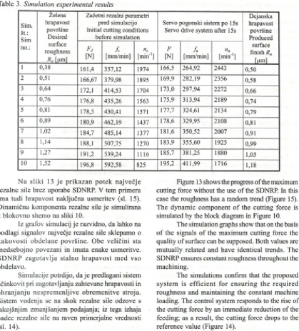
S sim ulacijam i sta testirani u čin k o v ito st in s ta b iln o s t SD N R P p ri ra z lič n ih z a h te v a h k a k o v o s ti p o v rš in e . M e rilo z a u č in k o v ito s t
sistem a je razlika m ed želeno in sim ulirano Ra.
V hodni podatki so začetni rezalni param etri in
želena Ra. V preglednici 3 so podane zahteve in
rezu ltati sim ulacij.
I z v e d e n ih j e 10 s im u la c ij. R e z u lta ti s im u la c ij (p re g i. 3) p o trju je jo , d a j e siste m d in am ičn eg a n a stav ljan ja re z a ln ih p aram etro v u č in k o v it pri n a d z o ru o b re m e n ite v o ro d ja in h ra p av o sti površine. U čin k o v it j e p ri natančni o b d elav i; to je še posebej raz v e se ljiv o , saj je n a m e n je n za o pravila o b lik o v n e g a fre z a n ja s p aličn im i frezali, k jer so zahteve po kakovosti o b d e la v e o stre. P ri o b d e la v i, k je r h ra p a v o st preseže 1,1 pm , se odzivnost sistem a upočasni. Z m an jša se n jeg o v a o b ču tljiv o st za doseganje želen e hrapavosti.
Using a simulation we can test the efficiency an d s ta b ility o f th e S D N R P w ith d iffe re n t requirements for the surface quality. The criterion fo r e fficien cy o f the system is the difference
between the desired and simulated Ra. The starting
cutting parameters and the desired Ra are the input
data. In Table 3 the requirements and the results of the simulations are indicated.
Sim. št.: Sim no.: Želena hrapavost površine Desired surface roughness
Ra [pm]
Začetni rezalni parametri pred simulacijo Initial cutting conditions
before simulation
Servo pogonski sistem po 15s Servo drive system after 15s
Dejanska hrapavost površine Produced surface finish Ra
[pm] Pd [N] fc [mm/min] nc
[m in ']
F
[N]
fa
[mm/min]
na
[m in 1]
i 0,38 161,4 357,12 1974 166,5 264,92 2443 0,50
2 0,51 166,67 379,98 1895 169,9 282,19 2356 0,58
3 0,64 172,1 414,53 1704 173,0 297,94 2272 0 ,6 6
4 0,76 176,8 435,26 1563 175,9 313,94 2189 0,74
5 0,81 178,5 430,41 1571 177,7 324,61 2134 0,79
6 0,89 180,9 462,19 1437 178,6 329,95 2108 0,81
7 1 , 0 2 184,7 485,14 1377 181,6 350,52 2007 0,91
8 1,14 188,1 507,75 1270 183,9 355,60 1925 0,99
9 1,27 191,2 539,24 1116 185,7 381,25 1880 1,05
1 0 1,52 196,8 592,58 825 195,2 411,99 1716 1,18
Preglednica 3. Preizkusni rezultati simulacij
Table 3. Simulation experimental results
N a slik i 13 j e p rik azan p o tek naj večje rezalne sile brez uporabe SDNRP. V tem primeru im a tudi hrapavost naključna usm eritev (sl. 15). D inam ična komponenta rezalne sile je simulirana z blokovno shemo na sliki 10.
Iz grafov simulacij je razvidno, da lahko na podlagi signalov največje rezalne sile sklepamo o k ak o v o sti obdelane površine. O be veličini sta m edsebojno povezani in imata enake usmeritve. SD N R P z a g o ta v lja stalno h rap av o st m ed vso obdelavo.
Simulacije potrdijo, d a je predlagani sistem učinkovit pri zagotavljanju zahtevane hrapavosti in o h ran jan ju nesprem enljive obrem enitve stroja. Sistem vodenja se na skok rezalne sile odzove s takojšnjim zmanjšanjem podajanja; iz tega izhaja padec rezalne sile na raven primerjalne vrednosti (sl. 14).
Stalne rezalne obrem enitve privedejo do boljše kakovosti površine in preprečijo nezaželene vibracije in povese rezalnega orodja. Izboljšanje kakovosti površine je najbolj opazno pri obdelavi kotov, žepov, utorov in ukrivljenih površin, pri katerih sistem z zmanjšanjem podajanja prepreči nezaželene povese ffezala.
S is te m n e k o lik o s la b š e s le d i h itrim sp rem em b am rezaln ih razm er; to je p osledica n je g o v e z a p le te n e z g ra d b e in n a p a k p ri m o d e lira n ju . V zro k za p o časn o o d z iv n o st in
Figure 13 shows the progress o f the maximum cutting force without the use o f the SDNRP. In this case the roughness has a random trend (Figure 15). The dynam ic component o f the cutting force is simulated by the block diagram in Figure 10.
The simulation graphs show that on the basis o f the signals o f the maximum cutting force the quality o f surface can be supposed. Both values are m utually related and have identical trends. The SDNRP ensures constant roughness throughout the machining.
The simulations confirm that the proposed sy stem is effic ie n t fo r en su rin g the req u ired roughness and maintaining the constant machine loading. The control system responds to the rise of the cutting force by an immediate reduction o f the feeding; as a result, the cutting force drops to the reference value (Figure 14).
Constant cutting loadings lead to a better quality o f surface and prevent undesirable vibrations and deflections o f the cutting tool. The improvement o f the surface quality is most obvious when machining comers, pockets, slots and curved surfaces, where the system prevents undesirable milling cutter deflections by a reduction o f the feeding.
nenatančnost je treba iskati tudi v načinu izgradnje sim ulacijskega m odela podajalnega servosistema. V s im u la to r S D N R P je v k lju č e n m o d e l p o d a ja ln e g a s e r v o - s is te m a , ki d e lu je po poenostavljeni prenosni funkciji (en. (3)). Ta je m a te m a tič n o iz p e lja n a na p o d la g i d o lo č il proizvajalca. S preizkusnim posnetjem dinam ike podajalnega servosistem a, je m ogoče odzivnost sistem a močno izboljšati.
R ezultati sim ulacij nakazujejo naslednje ugotovitve:
• M o d e ln o p o d p rt siste m za d in a m ič n o
nastavljanje rezalnih param etrov je zm ožen nadzorovati rezalno silo v širokem obm očju rezalnih parametrov.
• Zahtevana hrapavost se doseže s sim ultanim
nastavljanjem podajanja in rezalne hitrosti.
• Sistem je stabilen.
• Signali največjih rezalnih sil so v odvisnosti od
hrapavosti površine.
• N ajvečje odstopanje dejanske hrapavosti od
izmerjene je 4,1 %.
• Največje odstopanje vodene rezalne sile proti
primerjalni je 5,2 %.
• S istem j e n a jb o lj u č in k o v it p ri o p ra v ilih natančne obdelave, pri kateri hrapavost površine ne preseže 1,1 pm.
8 POVZETEK
V prispevku je predstavljen modelno podprt s is te m d in a m ič n e g a n a s ta v lja n ja re z a ln ih parametrov. Sistem z dinam ičnim prilagajanjem podajanja in vrtljajev obvladuje hrapavost površine ter rezalne sile na frezalu. M ed obdelavo spremlja vrednosti največjih rezalnih sil. Soodvisnost med hrapavostjo površine in rezalnimi silami določimo z metodo GP. Za primerjavo so izpeljane z metodo genetskega programiranja še m atematična razmerja m ed vplivnimi rezalnimi veličinami, ki so osnova za izd elav o ra č u n a ln išk ih sim u lacij v p a k e tu Simulink.
S sim ulacijam i je p otrjena u strezn o st in stabilnost sistem a vodenja. D okazano je, da lahko z o b v la d o v a n je m r e z a ln ih s il u s p e š n o n adzorujem o h rapavost površine, ki j e bistven k a z a ln ik k a k o v o sti p o sto p k a. Z o h ra n ja n je m nesprem enljive rezalne sile zagotavljam o stalno kakovost obdelane površine.
N a podlagi rezultatov številnih simulacij se odločim o, da preizkusno izvedemo opisan sistem
traced to the m anner o f the developm ent o f the simulation model o f the feeding servo-system. The SDNRP simulator incorporates the model of the feeding servo-system , w hich functions according to the simplified transfer function (Equation 3). The latter is mathematically derived on the basis o f the maker’s specifications. B y experim entally capturing the dynamics o f the feeding servo-system it is possible to considerably improve the responsiveness o f the system.
The simulation results indicate the following findings:
- A m o d e l-b a se d sy ste m fo r d y n a m ic a lly adjusting the cutting parameters is capable of controlling the cutting force over a wide range o f cutting parameters.
- The required roughness is reached by simultaneous
adjustment o f the feeding and cutting speeds.
- The system is stable.
- The signals o f the m axim um cutting forces
correlate with the surface roughness.
- The maximum deviation o f the actual from the
measured roughness is 4.1%.
- The maximum deviation o f the controlled from
the reference cutting force is 5.2%.
- T he sy stem is m o st e ffic ie n t d u rin g fine- m a c h in in g o p e ra tio n s, w h e re th e su rface roughness does not exceed 1.1 pm.
8 CONCLUSION
This paper presents a model-based system for dynam ically adjusting cutting param eters. By a dynamic adaptation o f the feeding and spindle speed the system controls the surface roughness and the cutting forces on the milling cutter. During machining it follows the values o f the maximum cutting forces. The correlation between the surface roughness and the cutting forces is determined by the GP method. Furthermore, mathematical relations between the influencing cutting values, on which the development o f the computer simulations in the package Simulink is based, are derived for comparison.
Using simulations the adequacy and stability o f the control system are confirmed. It was proved that the surface roughness, w hich is an important indicator o f the process quality, can be successfully controlled by controlling the cutting forces, and by m aintaining a constant cutting force a constant quality o f surface finish is ensured.
v o d e n ja . S istem j e z a sn o v a n za o p ra v ilo o b lik o v n e g a fre z a n ja , če p ra v ga j e m o g o če p r ila g o d iti za vse p o sto p k e o b d e la v e z o d re z o v a n je m . P rim e re n j e za v k lju č ite v v o b d e lo v a ln e siste m e , k i se u p o ra b lja jo v avtom obilski in orodjarski industriji. Odpravlja p ro b le m e , ki so p o v e z a n i z z a g o ta v lja n je m k akovosti obdelave, učinkovitosti obdelave in preprečevanjem poškodb orodja.
the described system o f control. The system was conceived for the end milling operation, although it can be modified for all processes o f machining by cutting. It is suitable for the incorporation into manufacturing systems used in the automobile and too l-m ak in g industries. It also elim inates the problems related to the ensurance o f the quality o f machining, the efficiency o f machining and the prevention o f tool damage.
7 LITERATURA 7 REFERENCES
[1] Ulsoy, A.G., Y. Koren (1993) Control o f machining processes, J. o f Dynamic Systems Measurement
and Control 115(1993), pp. 291-300.
[2] Balič, J. (2000) A new NC machine tool controller for step-by-step milling, Int. j. adv. manuf. technol.
8(2000) pp. 399-403.
[3] Cus, F., U. Zuperl, E. Kiker, M. M ilfelner (2006), Adaptive controller design for feedrate maximization
o f m achining process, Journal o f Achievements in Materials and Manufacturing Engineering
17(2006),pp. 237-240.
[4] Tlusty, J., M.A. Elbestawi (1977) Analysis o f transients in an adaptive control servomechanism for
milling with constant force, Transactions o f the ASME, Journal o f Engineering fo r Industry 99(1977),
pp. 766-772.
[5] Koren, Y. (1983) Computer control o f manufacturing systems, New York, McGraw±Hill, 1983
[6] Stute, G., F.R. Goetz (1975) Adaptive control system for variable gain in ACC systems, Proceedings
o f the Sixteenth International Machine Tool Design and Research Conference, Manchester England, pp. 117-121.
[7] Tomizuka, M., J.H. Oh, D.A. Domfeld (1983) Model reference adaptive control o f the milling process,
Proceedings o f the Symposium on Manufacturing on Manufacturing Process and Robotic Systems,
New York, (1983), pp.55-63.
[8] Huang, S.J., C.C. Lin (2002), A self-organising fuzzy logic controller for a coordinate machine, Int. J.
Adv. Manuf. Technol. 19(2002), pp.736-742.
[9] Ahmed, M.S. (1995) BPD computation and model reference adaptive control o f Hammerstein plants,
IEE Proceedings Part-D (Control Theory and Application), 142 (1995), pp. 475-485.
[10] Daeshmend, L.K., H.A. Pak (1986) M odel reference adaptive control o f feed force in turning, ASME
J. o f Dynamic Systems, Measurement and Control 108(1986), pp. 215-222.
[11] Liu, Y , L. Zuo, C. Wang (1999) Intelligent adaptive control in milling process, International Journal
o f Computer Integrated Manufacturing, 12(1999), pp. 453-460.
[12] Liu, Y , C. Wang, (1999) Neural networks based adaptive control and optimisation in milling process,
International Journal o f Advanced Manufacturing Technology 15(1999), pp. 791-795.
[13] Kopač, J. (2002) Rezalne sile in njihov vpliv na gospodarnost obdelave = Cutting forces and their
influence on the economics o f machining. Stroj, vestn. 3(2002), pp. 121-132.
[14] Milfelner, M., U. Župerl, F. Čuš (2005) Ustvarjanje modela rezalnih sil z uporabo umetne inteligence =
Generation o f a model for cutting forces using artificial intelligence. Stroj, vestn., 1 (2005), pp. 41-54.
[15] Ficko, M ., M. Brezočnik, J. Balič (2005) Oblikovanje prilagodljivega obdelovalnega sistem a z genetskimi algoritmi = A model for forming a flexible manufacturing system using genetic algorithms.
Stroj, vestn., 1 (2005), pp. 28-40.
[16] Ž uperl, U., F. Čuš, E. Kiker, M. M ilfelner (2005) K om biniran sistem ločenega optim iranja in prilagodnega nastavljanja rezalnih parametrov med procesom oblikovnega frezanja = A combined system for off-line optimization and adaptive adjustment o f the cutting parameters during a ball-end
[17] Župerl, U., F. Čuš (2004) D oločevanje značilnih tehnoloških in gospodarskih param etrov med postopkom odrezovanja = A determination o f the characteristic technological and economic parameters
during metal cutting. Stroj, vestn., 5(2004), pp. 252-266.
N aslov avtoijev: dr. Uroš Župerl prof. dr. Franci Čuš prof. dr. Edvard Kiker Univerza v Mariboru Fakulteta za strojništvo Smetanova 17
2000 M aribor
uros.zuperl@ uni-m b.si
A uthors’ address: Dr. Uroš Župerl Prof. Dr. Franci Čuš Prof. Dr. Edvard Kiker University o f M aribor Faculty o f Mechanical Eng. Smetanova 17
2000 Maribor, Slovenia uros.zuperl@ uni-m b.si
Prejeto: , nn7 Sprejeto: Odprto za diskusijo: 1 leto