An Experimental Investigation on Effect of Cutting Fluids in
Turning with Coated Carbides Tool
Yahya Isik
University of Uludağ, Department of Technical Science, Vocational School of Higher Education, Turkey
The major needs in machining are high material removal rate, good work surface finish and low tool wear. These objectives can be achieved by reducing tool wear using proper cooling system of the tool during machining. The work aims to seek conditions in which dry cutting is satisfactory compared with the flood of fluid usually used. The cutting tool used in this research is CVD coated carbide
TiC+AI2O3+TiN insert (ISO P25). The type of inserts is DNMG 150608. During the experiments flank
wear, cutting force and surface roughness value were measured throughout the tool life. The results have been compared with dry and wet-cooled turning. The results of the present work indicate substantial reduction in tool wear, which enhanced the tool life; this may be mainly attributed to reduction in cutting zone temperature and favorable change in the chip-tool interaction.
©2010 Journal of Mechanical Engineering. All rights reserved.
Keywords: flank wear, tool life, cooling, cutting forces, tool wear
0 INTRODUCTION
In metal cutting process, the condition of the cutting tools plays a significant role in achieving consistent quality and also for controlling the overall cost of manufacturing. The main problem caused during machining is due to the heat generation and the high temperature resulted from heat. The heat generation becomes more intensified in machining of hard materials because the machining process requires more energy than that in cutting a low strength material. As a result, the cutting temperatures in the tool and the work-piece rise significantly during machining of all materials [1]. At such elevated temperature the cutting tool if not enough hot hard may lose their form stability quickly or wear out rapidly resulting in increased cutting forces, dimensional inaccuracy of the product and shorter tool life. The magnitude of this cutting temperature increases, though in different degree, with the increase of cutting velocity, feed and depth of cut, as a result, high production machining is constrained by rise in temperature. This problem increases further with the increase in strength and hardness of the work material [2] and [3].
In dry cutting operations, the friction and adhesion between chip tool tend to be higher, which causes higher temperatures, higher wear rates and, consequently, shorter tool lives. Up to
this moment, completely dry cutting is not suitable for many machining processes. Since cutting fluid is necessary to prevent the chips from sticking to the tool and causing its breakage [4].
Isik, Y. 2
The major needs in machining are high material removal rate, good work surface finish and low tool wear. These objectives can be achieved by reducing tool wear using proper cooling system of the tool during machining. The main objective of using cutting fluids in machining operations is the reduction of temperature in the cutting region to increase tool life. The cutting fluids are used in machining operations in order to
(i) Reduce friction at the chip and tool-work-piece interfaces,
(ii) Cool both chip and tool, and (iii) Remove chip.
Furthermore, they have a strong effect on the shearing mechanisms and, consequently, on the work-part surface finish and tool wear [13] and [14].
The positive effect of the use of fluids in metal cutting was first reported in 1894 by F. Taylor [15], who noticed that by applying large amounts of water in the cutting area, the cutting speed could be increased up to 33% without reducing tool life. Since then, cutting fluids have been developed resulting in an extensive range of products covering most work-piece materials and operations. According to Kress [16], the costs associated with the use of cutting fluids represent approximately 17% of the finished work-piece cost against 4% spent with tooling. Kwon [17], studied flank wear by incorporating cutter temperature and physical properties of coating and work materials. The objective of this paper is to investigate the effects of internal cooling on the tool flank wear in orthogonal metal cutting. Diniz and Micaroni [4], carried out other experiments in turning operations of AISI 1040 steel, also using coated carbide tools and cutting conditions typical of finishing operations. Their goal was to compare dry cutting with cutting with abundant fluid at different feeds, cutting speed and tool nose radius.
The present work deals with experimental investigation in the role of cutting fluids on cutting temperature, cutting forces, tool wears, and surface roughness value in machining AISI-1050 steel at industrial speed-feed condition by CVD coated carbide TiC+AI2O3+TiN insert as compared to completely dry machining. This study indicated that cutting fluid did not show a significant improvement on surface roughness particularly when cutting tests with 0.8 mm nose
radius were considered. In fact, the roughness similarly deteriorated under wet machining in some of tests.
1 EXPERIMENTAL DETAILS
1.1 Cutting Tool Materials
Carbides are the most common tool material for machining of castings and alloy steels. These tools have high toughness, but poor wear characteristics. To improve the hardness and surface conditions carbide tools are coated carbide with hard materials such as TiN, TiC, TiAlN, and TiCN by chemical vapor deposition (CVD).
Currently, the most popular CVD coatings are titanium carbide (TiC), titanium nitride (TiN), titanium carbon nitride (TiCN), and alumina (Al2O3). The first successful CVD coating, TiC offers high hardness and excellent wear resistance. A later development, Al2O3 coatings, offers superior thermal stability, oxidation wear resistance, and high-temperature hardness. High-temperature characteristics of Al2O3, when it's deposited as a single layer or alternating multi-layer, provide increased productivity in high-speed machining of steels and cast irons.
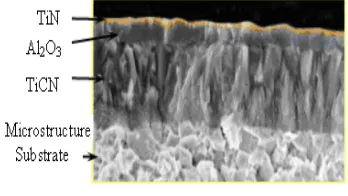
DNMG 150608 (with an ISO designation) carbide inserts, clamped on tool holders CSBNR 2525 M12. As cutting tools, CVD coated carbide TiC+AI2O3+TiN insert (ISO P25) were used in the experiments. Inserts possesses, a coating consisting of a TiCN under layer, an intermediate layer of Al2O3 and a TiN out layer, all deposited by CVD (Fig. 1).
Fig. 1. CVD coating layers of insert
1.2 Work-piece Material
0.050%S. Cylindrical work-pieces (Ø80×340 mm) were fixed between the chuck and the tailstock and were pre-machined by using a separate insert.
1.3 Machinability Test
Machining tests were carried out according with Standard ISO 3685 [18] which involves turning of a bar at a constant cutting speed (Vc) and the identification of the cutting time (Tc) necessary to obtain a specific value of tool flank wear. Since conventional 5.5 KW TOSS lathe was used in the tests, in order to have a constant cutting speed, in the turning operation 190 to 260 m/min of various cutting speed, 0.14 mm/rev of feedrate, 0.5 mm and 1 mm of depth cut values were used in all cases. As the tool life criteria, a value of 0.3 mm of average flank wear land (IB) that was established by ISO 3685, was used (Fig. 2). Coated carbide inserts, ISO DNMG 150608 (K10), clamped on tool holders CSBNR 2525 M12 were used in the tests, Cutting forces, flank wear and surface roughness values were measured until the tool expires.
The cutting forces were measured by a three-dimensional force dynamometer, Kyowa TD-500. The flank wear of the tool was measured by means of Nikon104 microscope with a magnification of X10 and the cutting process was paused in every 60 mm and the average flank
wear was measured. The work-piece surface roughness was measured by a profilometer (Taylor Hobson Talysurf Series 10). Oil based coolant was pumped at rate of 3 liter/min on the tool-work interface, so as to flood the cutting zone along with surrounding area in wet turning tests. The process parameters as indicated in Table 1 were selected on recommendation of tool manufacturers for machining AISI 1050 steel.
In the experiments, CVD coated carbide TiC+AI2O3+TiN cutting tool was taken into consideration throughout the tool life at certain cutting conditions. Parameter on tool life, was determined with respect to the recommendations advised by the tool manufacturers for the coated tools. For all tools, only the flank wear was taken into consideration in the comparisons. The result of experimental data is given in Table 2.
Fig. 2. Geometry of wear of turning tools [19]
Table 1. Experimental condition
Machine tool : TOSS, 5.5 KW, Lathe
Work specimens materials : AISI-1050 steel (0.52%C, 0.86%Mn, 0.040%P, 0.050%S.)
Size : (Cylindrical workpieces Ø80×340 mm)
Cutting tool : CVD Coated carbide, DNMG 150608(K10)
Coating : TiC+AI2O3+TiN
Tool holder : CSBNR 2525 M12 (ISO specification),
Working tool geometry : Inclination angle: 6, rake angle: 6, clearance angle: 6, cutting edge angle: 75
Principal nose radius: 0.8mm
Force dynamometer : Kyowa TD-500,
Microscope : Nikon104 with a magnification of X10
A profilometer : Taylor Hobson Talysurf 10
Process parameters
Cutting velocity, V : 190, 220, 240 and 260 m/min
Feed rate, f : 0.14 mm/rev
Depth of cut, a : 0.5, 1.0 mm
Isik, Y. 4
Table 2. Results of experimental data
Cutting parameters Flank
wear [mm]
The rate of flank wear [mm/min.]
The volume of material
removed [cm3/tool life]
Tool life
[min.] Cutting speed [m/min]
Feed rate [mm/rev]
Depth of cut [mm]
Cutting condition
0.35 0.0173 783.65 20.13 Dry
0.33 0.0146 814.35 22.55
1.0
Wet
0.35 0.0080 627.20 43.60 Dry
0.37 0.0063 705.63 58.27
260 0.14
0.5
Wet
2 RESULTS AND DISCUSSION
2.1 Tool Wear and Flank Wear
Cutting tools may fail by brittle fracture, plastic deformation or gradual wear. Turning carbide inserts having enough strength; toughness and hot hardness generally fail by gradual wear. With the progress of machining, the tools attain crater wear at the rake surface and flank wear at the clearance surfaces [19], the principal flank wear is the most important because it raises the cutting forces and the related problems.
Flank wear is a major form of tool wear in metal cutting. When machining using tools under typical cutting conditions, the gradual wear of the flank face is the main process by which a cutting tool fails [20] to [22].
According to ISO standard 3685 to tool life testing, the life of carbide tools, which mostly fail by wearing, is assessed by the actual machining time after which the average value (VB) of its principal flank wear reaches a limiting value of 0.3 mm [24]. In tool life evaluation turning processes were paused in every 60 mm and the average flank wear was measured. If the tool was not expired (which means it does not reach to a value of 0.3 mm of average flank wear land) at the end of the first bar, second bar of the same structure was used for the rest of the process. This was necessary for the constant cutting speed as explained previously.
Tool life estimation involves a number of tests to be carried out at various cutting conditions till the failure of the cutting tool. In general, as the tool life criterion, amount of flank wear is used. Flank wear (VB) is an important factor in determining the tool life. The cutting test was started with a new cutting tool, and the machining process was stopped at certain intervals of cutting length in order to measure the width of flank wear. Flank wear rate is calculated
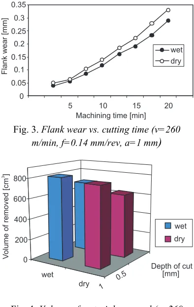
as the average wear (mm) divided by the effective tool life [min] [23]. The major advantage of wet-cooled turning seems to be reduction of tool wear at high speed. Fig. 3 shows the progression of flank wear in dry and wet-cooled turning and volume of material removed is shown Fig. 4.
Fig. 3. Flank wear vs. cutting time (v=260
m/min, f=0.14 mm/rev, a=1 mm
)
Fig. 4. Volume of material removed (v=260 m/min, f=0.14 mm/rev, a=1 mm, a=0.5 mm)
2.2Surface Finish
tool flank wear were used to evaluate the tool performance. In particular, the wear criterion adopted in the finish turning tests was based on a maximum allowed value imposed to the average surface roughness (Ra), according to the ISO 3685 [15].
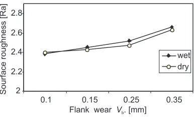
Two important performance parameters in turning process are tool life and surface roughness of the machined surface. For most tests, cutting speed and cutting fluid did not show a significant effect on surface roughness for both dry and wet machining conditions. The effect of the cutting speed is negligible. Figs. 5 and 6 shows the variation of surface roughness at different cutting speeds, and flank wear with time for dry and wet-cooled turning.
Fig. 5. Flank wear vs. surface roughness (v=260 m/min, f=0.14 mm/rev, a=1 mm)
Fig. 6. Cutting speeds vs. surface roughness
The major advantage of using cutting fluids in machining operations is reduced of tool wear at high speed. The other advantage is the lowering of cutting forces. Fig. 7 illustrates the tool life at different cutting speeds and constant depths of cut at a feed rate of 0.14 mm/min with dry and wet-cooled turning. When cutting speed increases, Tool life decreases as is expected. But, tool life more decreases for wet cutting than dry cutting. This is because application of flood fluid
reduces the coefficient of friction at the interface of the tool and chip over the rake face. This is achieved through lubrication, and by lowering the strength of welded junctions between the tool and chip.
Fig. 7. Tool life at different cutting speeds (f=0.14 mm/rev, a=1 mm, a=0.5 mm)
Fig. 8. Tangential cutting force versus cutting time with dry and wet cooled condition
2.3 Cutting Forces
Isik, Y. 6
the dry cutting can also be seen from Fig. 8. It is very clear from the curves that cutting force in wet-cooled cutting is less than that of dry cutting.
3 CONCLUSIONS
Based on the results of the experimental investigation the following conclusions can be drawn:
1. The coolant helps breaking up chips and removing them from the cutting area more efficiently, which means the cutting tool spent less time for breaking metal chips. 2. The cutting fluid has significantly reduced
the amount of heat and friction at the point where a tool cuts into a metal work piece. 3. For most tests, cutting speed did not show a
significant effect on surface roughness for both dry and wet machining conditions. The effect of the cutting speed is negligible. 4. The results of the present work indicated that
cutting fluid did not show a significant improvement on surface roughness particularly when cutting tests with 0.8 mm nose radius were considered. In fact, the roughness similarly deteriorated under wet machining in some of tests.
5. CVD coated carbide TiC+AI2O3+TiN cutting tool performed better during wet machining mode.
6. The results of the present work indicate substantial reduction in tool wear, which enhanced the tool life; this may be mainly attributed to reduction in cutting zone temperature and favorable change in the chip-tool interaction.
7. The cutting fluid enabled in reducing the main cutting force due to improved and intimate chip-tool interaction.
8. It provided more efficient chip removal and heat reduction.
4 REFERENCES
[1] Ahsan, A.K., Mirghani, I.A. (2008) Improving tool life using cryogenic cooling, Journal of Materials Processing
Technology, vol. 196, p. 149-154.
[2] Dhar, N.R., Ahmed, M.T., Islam, S. (2007) An experimental investigation on effect of minimum quantity lubrication in machining AISI 1040 steel, International
Journal of Machine Tools & Manufacture,
vol. 47, p. 748-753.
[3] Dhar, N.R., Kamruzzamanb, M. (2007) Cutting temperature, tool wear, surface roughness and dimensional deviation in turning AISI-4037 steel under cryogenic
condition, International Journal of
Machine Tools & Manufacture, vol. 47, p.
754-759.
[4] Diniz, A.E., Micaroni, R. (2002) Cutting conditions for finish turning process aiming: the use of dry cutting, International Journal of Machine Tools &
Manufacture, vol. 42, p. 899-904.
[5] Çakır, O., Kıyak, M., Altan, E. (2004) Comparison of gases applications to wet and dry cuttings in turning, Journal of
Materials Processing Technology, vol.
153-154, p. 35-41.
[6] El Baradie, M.A. (2007) Cutting fluids Part I. characterization, Journal of Materials
Processing Technology, vol. 56, p.
787-797.
[7] Yildiz, Y., Gunay, M., Seker, U. (2007) The effect of the cutting fluid on surface roughness in boring of low carbon steel– technical communication, Machining
Science and Technology, vol. 11, p.
553-560.
[8] Stanford, M., Lister, P.M., Kibble, K.A. (2007) Investigation into the effect of cutting environment on tool life during the milling of a BS970-080A15 (En32b) low carbon steel, Wear, vol. 262, p. 1496-1503.
[9] Klocke, F., Eisenblaetter, G. (1997) Dry
cutting, CIRP Annals-Manufacturing
Technology, vol. 46, no. 2, p. 519-526.
[10] Silliman, J.D., Perich, R. (1992) Cutting and grinding Fluids: selection and
application-Second Editio. Society of
Manufacturing Engineers,p. 216.
[11] Bienkowski, K. (1993) Coolants & lubricants-staying pure, Manufacturing
Engineering, p. 55-61.
[12] Diniz, A.E., Oliveira, A.J. (2004) Optimizing the use of dry cutting in rough turning steel operations, International Journal of Machine Tools and
Manufacture, vol. 44, p. 1061-1067.
lubrication condition on SAE 52100 hardened steel turning at several cutting speed, International Journal of Machine
Tools and Manufacture, vol. 43, p.
317-326.
[14] Vikram Kumara Ch R., Ramamoorthy, B. (2007) Performance of coated tools during hard turning under minimum fluid
application, Journal of Materials
Processing Technology, vol. 185, p.
210-216.
[15] Taylor, F.W. (1906) On the art of cutting
metals, Trans. ASME, p. 28-31.
[16] Kress, D. (1997) Dry cutting with finish machining tools, Ind. Diam. Rev., vol. 74, p. 81-85.
[17] Kwon, P. (2000) Predictive models for flank wear on coated Inserts, International
Journal of Tribology, vol. 122, no. 1, p.
340-347.
[18] Anon (1993) Tool-life testing with single-point tools, ISO 3685:1993 (E).
[19] Dhar, N.R. (2001) Effects of cryogenic cooling by liquid nitrogen jets on
machinability of steels, Journal of
Materials Processing Technology, vol.
116, p. 44-48.
[20] Luo, X., Cheng, K., Holt, R., Liu, X. (2005) Modeling flank wear of carbide tool insert in metal cutting, Wear, vol. 259, p. 1235-1240.
[21] Haron, C.H.C., Ginting, A., Goh, J.H. (2001) Wear of coated and uncoated carbides in turning tool steel, Journal of
Materials Processing Technology, vol.
116, p. 49-54.
[22] Jawaid, A., Che-Haron, C.H., Abdullah, A. (1999) Tool wear characteristics in turning of titanium alloy Ti-6246, Journal of
Materials Process Technology,vol. 92-93,
p. 329-334.
[23] Ezugwu, E.O., Okeke, C.I. (2001) Tool life and wear mechanisms of TiN coated tools in an intermittent cutting operation, Journal of Materials Processing
Technology, vol. 116, p. 10-15.
[24] Ezugwu, E.O., Da Silva, R.B., Bonney, J., Machado A.R. (2005) Evaluation of performance of CBN tools when turning Ti-6Al-4V alloy with high pressure coolant supplies, International Journal of Machine
Tools and Manufacture, vol. 45, p.
![Fig. 2. Geometry of wear of turning tools [19]](https://thumb-us.123doks.com/thumbv2/123dok_us/8952902.1862270/3.539.282.481.287.396/fig-geometry-of-wear-of-turning-tools.webp)