Iranian Journal of Electrical and Electronic Engineering, Vol. 15, No. 1, March 2019 76
Modeling and Efficient Control of Microturbine Generation
System With Battery Energy Storage for Sensitive Loads
P. Asgharian* and R. Noroozian*
(C.A.)Abstract: Microturbine generation system is one of the most promising and a fast growing distributed generation sources. It is used in various applications thanks to high efficiency, quick start and high reliability. Combination of the microturbine and storage system (e.g. battery bank) is desirable selection to satisfy the load requirements under all conditions and hence the battery bank can play an important role in restoring balance between source and demand. In this paper, modeling of the microturbine with battery energy storage system is presented to supply sensitive loads. Appropriate power exchange between battery and the microturbine is an essential issue so, a new control method is proposed for battery energy storage based on instantaneous value of DC-link voltage. In this new strategy, DC-link voltage as well as battery parameters (current and voltage) are used in order to produce desirable DC-DC switching. A control scheme based on voltage, current and frequency measurement is presented for the corresponding inverter. Simulations are carried out in MATLAB/Simulink software and the results show that storage along with proper control improves system reliability to supply sensitive load. The proposed configuration can be used as a remote power, emergency power and also in micro-grid.
Keywords: Microturbine Generation System, Battery Energy Storage, New Control Strategy, Isolated Mode, Sensitive Load.
1 Introduction1
HE Microturbine (MT) generation (MTG) system is a relatively new Distributed Generation (DG) and fast growing technology which is appropriate for small scale generation [1] because of compact size, quick start, long life time, reliability and durability, low initial and maintenance costs, low emission level, and ability of operation with alternative fuels including natural gas, biogas and diesel [2]. The MTG is indeed a small gas-turbine which operates based on Brayton thermodynamic cycle [3]. Smaller size and higher power density are desirable factors to use MT in any low power demand areas instead of conventional gas-turbine. The MT generates power within the range of 25-1000 kW and its efficiency is around 20-30% [4],
Iranian Journal of Electrical and Electronic Engineering, 2019. Paper first received 05 August 2018 and accepted 18 October 2018. * The authors are with the Department of Electrical Engineering, Faculty of Engineering, University of Zanjan, Zanjan, Iran.
E-mails: [email protected] and [email protected]. Corresponding Author: R. Noroozian.
where up to 80% can also be achieved by Combined Heat and Power (CHP) system [2]. These generation systems are used for a wide range of applications such as peak shaving, CHP, remote power, premium power, transportation system, resource recovery, base load power and stand by services [4].
The literature review shows there is extensive thrust on application of the MTG for reliable DGs. Research areas include simulation and development of inverter-interfaces MTs. Detailed dynamic modeling and simulation of a MTG is presented in [5] and [6] that are the first papers in this area. Modeling, simulation and control of AC-DC-AC based MTG for isolated and grid-connected modes is well pursued in many research work such as [7-10]. In [11] simultaneous isolated and grid-connected mode operation of the MTG along with boost converter and also a novel passive filter, namely Remover Ripple Circuit (RRC), is presented to supply a non-linear load. Mentioned references use classical control at steady state operation.
Dynamic modeling, simulation and performance analysis of a MTG based on gas-turbine governor model (GAST) is illustrated in [12] and [13]. In [12],
T
Iranian Journal of Electrical and Electronic Engineering, Vol. 15, No. 1, March 2019 77 additional voltage controller as well as speed controller
and active power controller is applied for load-following performance of the MTG system. In [13] dynamic modeling and active power control is explained to supply individual resistive-inductive (RL) loads and connection to distributed network. In [14] detailed model of MTG component and controllers with novel P-V control strategy is proposed.
Recently, researches focus on hybrid micro-grid in which there are renewable sources with back-up generations like MTG or diesel generator along with Battery Energy Storage (BES). In [15] dynamic modeling, energy management and control of isolated power generation consisting of a MT, a tidal turbine, an offshore wind turbine and a lead-acid battery storage is presented. The MTG with battery are used as back-up generation and it is applied to various control methods so as to management optimal sizing of the hybrid system and extraction of maximum energy from wind turbine. In order to achieve high reliability and uninterrupted power supplying with low pollution, the photovoltaic (PV) system integrated with the MTG is suggested in [16]. Full load and part load performance of a Solid Oxide Fuel Cell (SOFC) coupled with four different commercially available MT is reported in [17] that reveals useful data. In [18] combination of SOFC and MT is suggested to supply a rural micro-grid. Fuel of the MT is biogas as a renewable energy and a Three-Levels Neutral Point Clamped (3LNPC) inverter is as an interface for hybrid power system.
However, the mentioned studies are not reliable enough under isolated operation conditions and requires extensive investigation to resolve the technical issues. When the load increases or suddenly decreases, DC-link variations become challenging. The MTG with Energy Storage (ES) system can be used as an individual DG to ensure the availability of power at the load terminals in any situation.
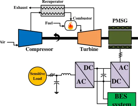
Fig. 1 shows an isolated single-shaft MTG with BES system. According to Fig. 1, ambient air enters the compressor and then, the compressed air mixes with fuel in combustor section. High pressure and hot exhaust air passes through a turbine that is coupled to a high frequency generator to generate electricity [2]. In order to reduce fuel consumption, the heat of turbine expanded gasses transfers to compressor discharges by a recuperator. The MTG high frequency produced voltage is converted to direct voltage through AC-DC converter and then converted back to alternative voltage through DC-AC inverter. A BES system is connected so as to regulate output voltage and active power. This system operates in isolated mode to supply a sensitive load and it can interact with other DGs as a back-up source. This paper presents dynamic modeling of the MTG with the BES system that is supplying a sensitive load. This system can be used as an individual DG in rural or impassable places to reduce costs and improve reliability. Suitable power flow of battery pack is an
essential issue and hence a new control strategy is tested based on Hysteresis Current Control (HCC). In this method, instantaneous measurement of DC-link voltage along with battery current and voltage enters the HCC system for appropriate switching. With the help of predefined limits, the DC-link voltage instantaneous monitoring causes the utilized control strategy to suppress load variations. The hysteresis bands determine switching time interval so a proper power flow occurs in order to respond to load demands. The DC-AC inverter control uses current, voltage and frequency to obtain sturdy control instead of classical control. The suggested model is simulated in MATLAB/Simulink environment with the simulation results showing that the battery/microturbine hybrid energy storage technology with the new control scheme can guarantee power quality supplied for costumers without voltage fluctuations. The paper is structured as follows. The BES and inverter control circuits are outlined in section 2, the MTG simulation results with and without BES is presented in section 3 and section 4 is dedicated to conclusion.
2 Model Description
This section is dedicated to the modeling of MTG and interface converters. The MTG dynamic modeling can be found in many studies such as [2, 5, 11]. The MTG two poles generator parameters are presented in Appendix [2]. The BES new control strategy along with storage configuration and the inverter control is expressed in the following subsections.
2.1 Isolated Inverter Control Scheme
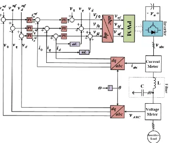
Adjustment of frequency and voltage is main purpose of V-f control method which brings about desirable power flow [19]. The inverter control scheme in isolated mode has been demonstrated in Fig. 2. The measured voltage and current are compared with reference values and then regulated by Proportional Integral (PI)
Compressor Turbine
Air
Fuel
Combustor Recuperator
PMSG
AC
DC
DC
AC
BES
system
SensitiveLoad Exhaust
Fig. 1 Single-shaft MTG system with BES in isolated mode.
Iranian Journal of Electrical and Electronic Engineering, Vol. 15, No. 1, March 2019 78 Fig. 2 Control of three-phase inverter in isolated mode.
controllers. The frequency is obtained through a Phase Locked Loop (PLL) and also a LC filter is installed at the load terminal to omit output harmonics.
The voltage and current equations to describe Fig. 2 are achieved by simple Kirchhoff's Voltage and current Laws (KVL & KCL). Obtained equations can be expressed as:
a A
b B
c C
a
b
c
v v i
d
v v L i
dt i
v v
(1)
0
a b c
i i i (2)
where va, vb and vc are inverter output line-to-neutral
voltages, vA, vB and vC are line-to-neutral load voltages,
L is filter inductance and ia, ib and ic are output currents
of inverter. According to Fig. 2, the control scheme is based on direct-quadrature-zero (dq0) synchronously rotating reference frame. The inverter control circuit consists of an inner current loop and an outer voltage loop that they have independent PI controllers [19]. At first, the measured three-phase output voltages as well as currents are transformed from stationary abc to rotating dq0 frame. The voltage equation according to (1) in dq0 frame is as follows:
0 0 0 0
fd d d q
fq q q d
f
v v i i
d
v v L i L i
dt
v v i
(3)
where id, iq and i0 are currents before the filter in dq0
frame, vfd, vfq, vf0and vd, vq, v0 are voltages before and
after the LC filter in dq0 frame, respectively.
The reference currents in the inner control loop are supplied by voltages:
ref ref
d d d
i PI v v (4)
ref ref
q q q
i PI v v (5)
0 ( 0 0)
ref ref
i PI v v (6)
Finally, the output voltages from the PI controllers can be expressed as (7)–(9):
( ref )
fd d d d q
v PI i i v
Li (7)( ref )
fq q q q d
v PI i i v
Li (8)0 ( 0 0) 0
ref f
v PI i i v (9)
The control signals are obtained through inverse transformation from dq0 to abc frame. Appropriate switching is generated through Pulse Width Modulation (PWM) block by transformed voltages vaf, vbf and vcf.
This sturdy control strategy produces sinusoidal waveform with a low Total Harmonic Distortion (THD).
2.2 The BES System Modeling
Recently, the ES technologies have found a significant role in power systems, since the number of various applications which require a certain voltage level over a short period of time has increased [20]. The MTG in
Iranian Journal of Electrical and Electronic Engineering, Vol. 15, No. 1, March 2019 79 isolated mode can utilize a large on-board battery bank
so as to supply connected loads when especially no electric grid is available [21].
The main technologies which have been used for BES are lead-acid, lithium-ion (Li-ion), nickel-metal hydride (NiMH) and lithium polymer [20]. The rechargeable Li-ion batteries are fast growing type and their advantages include high energy efficiency, long cycle life, no memory effects, low discharge rate, low footprint, high voltage [22] and being appropriate for power ranges of 1 kW to 1 MW. In this paper, lithium-iron-phosphate (LiFePO4) rechargeable battery pack is used since this type enjoys the highest specific power, safety and lifespan along with moderate costs.
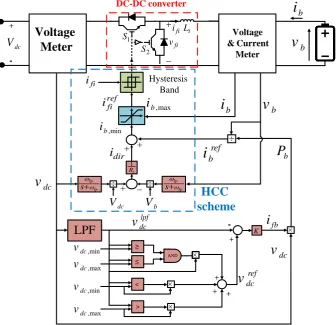
The BES control scheme is vital for proper support of the MTG. In this paper, a new HCC strategy is proposed to deal with the desired power flow. Fig. 3 shows the BES system control scheme that consists of an outer loop together with an inner loop. The former provides active power based on the measured DC-link voltage, while the latter is HCC to apply appropriate switching for a DC-DC interface converter.
According to Fig. 3, vdcref is the reference voltage of
the storage control system, Kis the controller gain, ib
and vb represent the battery’s measured current and
voltage, respectively, Pbshows the battery power [23]
and the interface is a simple two-switch DC-DC converter. The Measured DC-link voltage is filtered by
a Low-Pass Filter (LPF) with a constant frequency of
ωlpf.:
lpf dc lpf lpf dc v v s (10)
The reference DC-link voltage, vdcref, is dependent on
two predefined limits (i.e. vdc,max and vdc,min). The current
resulting from DC-link for the storage is called ifb.
( ref lpf )
fb dc dc
i K v v (11)
The reference signal of active power is obtained by multiplying ifb by DC-link voltage.
( ref lpf )
b dc fb dc dc dc
P v i Kv v v (12)
According to (12), the battery bank power is relied on the DC-link voltage. When mentioned voltage places between vdc,max and vdc,min, the power signal, Pb, is equal
to zero and hence power is not generated. When the DC-link voltage is greater than vdc,max, Pb is negative, so
the storage is charged through additional power. Conversely, when the DC-link voltage is lower than
vdc,min, the battery discharges and Pb signal is
positive [23]. The battery current reference signal for switching is as follows:
≥ < ≤ > + + + +
-LPF
AND + -bv
bi
dcv
bi
v
bb
P
ref bi
fbi
K dcv
ref dcv
,min dcv
,max dcv
,min dcv
,max dcv
i L fi i 1 S 2 S fi v lp
lp s i R 1 fi
i
lp lp s diri
ref fii
i
b,max,min b
i
bV
dcV
Hysteresis Band DC-DC converter Voltage & Current MeterVoltage
Meter
HCC
scheme
dcV
lpf dcv
Fig. 3 The BES system control scheme.
Iranian Journal of Electrical and Electronic Engineering, Vol. 15, No. 1, March 2019 80 ref b b b p i v (13)
This reference current together with battery currents and measured voltages enter the HCC system. In the HCC system, currents are compared to provide switching signal for the storage DC-DC converter. Indeed, the HCC is a current control method in which the measured current must track the reference within a hysteresis band [24]. The advantages of the HCC method include simplicity, excellent dynamic performance, unconditioned-stability, independent of load parameters, robustness and sensitivity to fluctuations of system parameters [24]. The control system of the BES interface converter should have fast dynamic response to properly adjust the power flow in the DC-bus. The BES reference current is achieved by battery active power and also the BES measured current determines the current limits (bands) for converter switching.
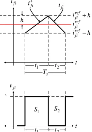
Fig. 4 depicts current variations in the hysteresis band to produce proper switching signals. Under normal conditions, the power direction is adjusted in order to flow from a higher to a lower voltage level, which is related to reference. The BES voltage is compared with DC-link voltage in p.u. scale and hence current idir,
which shows the direction of power flow, is produced using a resistive voltage droop (i.e. Ri). Equation (14) is
recommended for DC-DC interface converter instantaneous power based current calculator:
, ,
( dc pu b pu)
dir
ref ref ref
fi b b
i
v v
i i i i
R
(14)
It is worth noting that ifiref and ifi are the inputs of HCC
system two levels hysteresis comparator. The HCC switching frequency should be limited within a proper range since it is variable.
Mentioned issue is considered in designing of the inductor Li. When ifi- crosses lower hysteresis band,
switch S1 is turned on. Similarly, when rising current
(ifi+) touches the upper band, switch S2 is turned on.
Needless to say that h is fixed hysteresis band. By resistance ignoring, following equations can be written in switching intervals t1 and t2.
( b dc) fi i v v di dt L (15) dc fi i v di dt L
(16)
According to Fig. 4, (17)–(19) are concluded:
1
( )
. 2
ref fi fi
d i i
t h dt (17) 2 ( ) . 2 ref fi fi
d i i
t h
dt
(18)
1 2
1 s
s
t t T
f
(19)
where fs is the switching frequency.
By substituting of (15) and (16) into (17) and (18), following equations are achieved:
1
1 1
1
( )
( ) 2
( )
2
( ) 2
ref
b dc fi
i
ref
b dc fi
ref
b dc fi
i
v v di
t h
L dt
v v di
t h t
L dt
i
v v h di
L t dt
(20)
2
2 2
2
( ) 2
2 2 ref dc fi i ref dc fi i ref dc fi i v di t h L dt v di
t h t
L dt
v h di
L t dt
(21)
Two latter equations are equal, so we can write:
1 2
1 2
1 2 1 2 1 2
( ) 2 2
2 2
1 1
2
2
b dc dc
i i b i b i b i
v v h v h
L t L t
v h h
L t t
v T
hL t t t t
v
h t t
L T
(22)
According to (19), following statement can be rewrite:
2 2
1 2
2 2 2
1 2 1 2
2 2 2
1 2 1 2 ( ) ( ) 2 ( ) 2 2 s s s
t t T
t t t t T
T t t
t t
(23)
By substituting of (23) into (22):
2 2 2
1 2
2 2
1 2
2 2 2
4 4
b s
i s
b s b
i i s
v T t t
h L T
v T v
t t
L L T
(24)
Since t1 and t2 are very short time, we can ignore
second term of (24). Finally, according to (24) and the HCC concept, (25) is obtained:
4 b i s v h L f (25)
Iranian Journal of Electrical and Electronic Engineering, Vol. 15, No. 1, March 2019 81 Moreover, maximum switching frequency is given by vb
= Vb,max.
,max ,max
4 b s
i
V f
L h
(26)
where, fs,max is the maximum switching frequency and
Vb,max is converter maximum steady-state capacitive
terminal voltage. With respect to (25), the inductor (Li)
of DC-DC converter can be calculated in which nominal values are substituted.
, ,
1 4
ref b
i b
s n
V L
hf
(27)
where, fs,n is allowable converter switching frequency,
Vref,b is reference voltage and δb is battery nominal
droop.
3 Simulation Results
This section investigates the MTG load following performance with and without the BES (Fig. 1). The Simulation has been accomplished using MTLAB/Simulink software, with respect to studied system parameters in TABLE I. The outputs are plotted in p.u., as it is simple and easy to understand.
In this study, a variable load is considered in both states. At first, Load A is connected to MTG and then at
t = 3s, Load B is applied to the system. Similarly, at t = 4.5s, Load C is applied and the secondary and tertiary additional loads are disconnected at t = 6sand t = 8s, respectively. The measured DC-link voltage is sent to the storage control for interface converter switching. At
t = 0.5s, the battery isolated switch is ON and then battery is connected to the system with full charge. The desirable three-phase voltage amplitude and frequency are 400 V and 50 Hz, respectively.
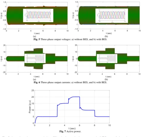
Fig. 5 shows three-phase voltages that have constant amplitude. Inside figures are magnification of outsides. When additional load is applied to the system, transient voltage drop occurs, but the inverter voltage controller regulates the voltage value to remain at 400 V (1 p.u.). Fig. 5(b) displays better voltage profile due to presence of the BES.
Three-phase currents are shown in Fig. 6 that inside are magnified. When the load increases, currents grow too and vice versa. The current values for Load A, Load B and Load C are 3.7 p.u., 11.8 p.u. and 15 p.u., respectively. According to Fig. 6(b), the currents reach proper value within shorter time, with the transients being lower than in the system without BES.
t
fi
i
fi
i
ref fi
i
h
1
t
t
2s
T
t
fi
i
fi
v
1
S
S
2h
i
reffi
h
i
reffi
1
t
t
2b v
Fig. 4 Current variation in the hysteresis band to generate switching signals
Table 1 Studied system parameters.
Parameter Value Parameter Value Parameter Value
MTG output power 30 kW LC filter capacitor 300 µF Base power 1 kW
MTG output frequency 1.6 kHz Fundamental frequency 50 Hz Base voltage: VL-L 400 V MTG output voltage: VL-L 480 V Inverter switching frequency 2 kHz LiFEPO4 battery capacity 10 Ah
DC-link voltage 760 V Load A 5 kW LiFEPO4 battery voltage 12 V
DC-link capacitor 3200 µF Load B 10 kW LiFEPO4 battery lifecycle 2,000 cycle
LC filter inductance 3 mH Load C 5 kW
Iranian Journal of Electrical and Electronic Engineering, Vol. 15, No. 1, March 2019 82
(a) (b)
Fig. 5 Three-phase output voltages: a) without BES, and b) with BES.
(a) (b)
Fig. 6 Three-phase output currents: a) without BES, and b) with BES.
Fig. 7 Active power.
Fig. 7 shows the active power variations. When load grows, the power increases too and vice versa. Power changes are matched with load demand which are 5 kW, 15 kW and 20 kW and hence the MTG load following performance is desirable. The power changes quickly to meet the load demands.
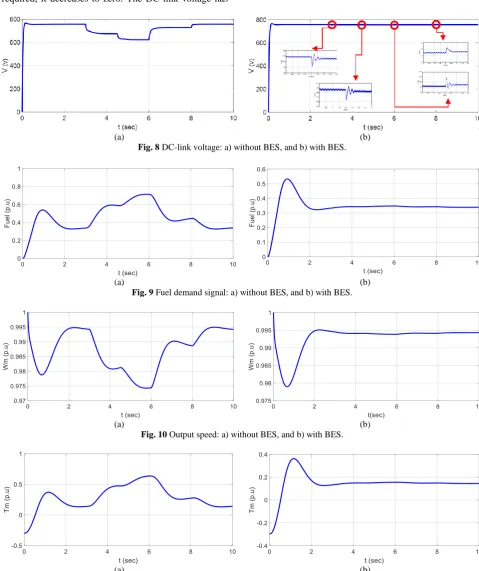
DC-link voltage variation is demonstrated in Fig. 8. At first, the DC-link Voltage is equal to 758 V and when additional loads are connected, it drops to 675.5 V and 626 V. In other words, heavy loads require more power which lead to a significant voltage drop. Fig. 8(b) exhibits the detailed DC-link voltage in which the storage system provides a stable voltage. When the DC-link voltage starts to decrease, the BES control system transfers an appropriate power flow to regulate the voltage.
Fig. 9 shows fuel demand variations. When additional
loads connect to the MTG, more fuel requires to meet the load demands and hence fuel valve will open. Finally, the value of the fuel demand reaches 0.7 p.u. Note that the MTG output signals are affected by the fuel system fluctuation. According to Fig. 9(b), the load changes have not effects on the fuel signal.
The output speed changes are opposite to the fuel signal’s. Fig. 10 displays the generator output speed that drops to 0.975 p.u. for the third load. Fig. 10(b) shows a constant speed at which significant speed drop is resolved.
Fig. 11 shows the MTG mechanical torque, which is reached to 0.65 p.u. Similar to the output power, the torque is changed in line with the loads. When the BES is connected, the torque remains at 0.18 p.u. without any variation.
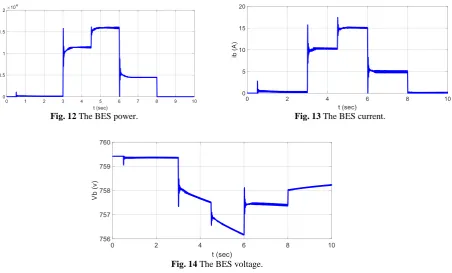
The BES bank power is shown in Fig. 12. When the
Iranian Journal of Electrical and Electronic Engineering, Vol. 15, No. 1, March 2019 83 load rises, the power injected to the system grows too
and vice versa. The BES provides a constant voltage in DC-link and supplies the load.
Fig. 13 shows the BES current. The current increases with additional load and when no storage system is required, it decreases to zero. The DC-link voltage has
been compared with the voltage limits to provide appropriate load following performance.
Voltage variation of the BES bank is shown in Fig. 14. When the load decreases, the voltage increases to its initial value.
(a) (b)
Fig. 8 DC-link voltage: a) without BES, and b) with BES.
(a) (b)
Fig. 9 Fuel demand signal: a) without BES, and b) with BES.
(a) (b)
Fig. 10 Output speed: a) without BES, and b) with BES.
(a) (b)
Fig. 11 Output torque: a) without BES, and b) with BES.
Iranian Journal of Electrical and Electronic Engineering, Vol. 15, No. 1, March 2019 84
Fig. 12 The BES power. Fig. 13 The BES current.
Fig. 14 The BES voltage.
Storage system has an effective role in production of a constant voltage and a desirable MTG performance. When additional loads are applied, the storage system operates to supply demands within a short time.
4 Conclusion
Recently the MTG based DG has been expanded thanks to potential merits and many advantages. One of the most important applications of the MT is emergency power or uninterruptable power source, in which appropriate supply of loads is essential. When power demand increases, significant voltage drop occurs at the terminals and hence use of an ES system is suggested. In this paper, dynamic modeling of the MTG along with BES system connected to DC-link is presented to supply sensitive loads. The ES system provides load demands so load variations do not any effect on the output voltage. In order to achieve the desirable power flow, a new control strategy is used for BES system and a sturdy control method is applied to three-phase inverter. Simulation results indicate that this system is a promising choice for remote power or emergency power and can not only guarantee high reliability but also continues operation for customers.
5 Appendix PMSG Parameters
Rated power = 30 kW, Rated voltage = 550 V, Rated frequency = 1600 Hz, Rs = 0.253 Ω, Lq =Ld=0.6875 mH,
P = 2, J = 0.011 kg.m2, F = 0, λ = 0.0534 Wb.
References
[1] P. Breeze, Gas-Turbine Power Generation. Netherland: Elsevier Science & Technology Books, pp. 77–82, 2016.
[2] P. Asgharian and R. Noroozian, “Microturbine generation power systems,” in Distributed generation systems: Design, operation and grid integration, 1st ed., G. B. Gharehpetian and S. M. Mousavi Agah, Eds. Netherland: Elsevier Science & Technology Books, pp. 149–219, 2017.
[3] M. S. Ismail, M. Moghavvemi, and T. M. I. Mahlia, “Current utilization of microturbines as a part of a hybrid system in distributed generation technology,”
Renewable & Sustainable Energy Reviews, Vol. 21, pp. 142–152, 2013.
[4] P. Asgharian and R. Noroozian, “Dynamic Modeling of a microturbine generation system for islanding operation based on model predictive control,” in 31st international Power System
Conference (PSC), Tehran, Iran, 2016.
[5] S. R. Guda, C. Wang, and M. H. Nehrir, “Modeling of microturbine power generation systems,” Electric Power Components and Systems, Vol. 34, No. 9, pp. 1027–1041, 2006.
[6] R. Lasseter, “Dynamic models for micro-turbines and fuel cells,” in IEEE Power Engineering Society
Summer Meeting, Vancouver, Canada, 2001.
Iranian Journal of Electrical and Electronic Engineering, Vol. 15, No. 1, March 2019 85 [7] S. K. Nayak and D. N. Gaonkar, “Performance
study of distributed generation system in grid connected/isolated modes,” Distributed Generation & Alternative Energy Journal, Vol. 29, No. 1, pp. 61–80, 2014.
[8] S. Sarajian, “Design and control of grid interfaced voltage source inverter with output LCL filter,”
International Journal of Electronics
Communications and Electrical Engineering, Vol. 4, No. 3, pp. 26–40, 2014.
[9] G. Saravanan and I. Gnanambal, “Design and efficient controller for micro turbine system,”
Circuits and Systems, Vol. 7, pp. 1224–1232, 2016.
[10]A. Tyagi and Y. K. Chauhan, “A prospective on modeling and performance analysis of micro-turbine generation system,” in IEEE International Conference on Energy Efficient Technologies for Sustainability (ICEETS), Nagercoil, India, 2013.
[11]P. Asgharian and R. Noroozian, “Modeling and simulation of microturbine generation system for simultaneous grid-connected/islanding operation,” in
IEEE 24th Iranian Conference on Electrical
Engineering (ICEE), Shiraz, Iran, 2016.
[12]G. Shankar and V. Mukherjee, “Load-following performance analysis of a microturbine for islanded and grid connected operation,” International Journal of Electrical Power & Energy Systems, Vol. 55, pp. 704–713, 2014.
[13]A. K. Saha, S. Chowdhury, S. P. Chowdhury, and P. A. Crossley, “Modeling and performance analysis of a microturbine as a distributed energy resource,”
IEEE Transactions on Energy Conversion, Vol. 24, No. 2, pp. 529–538, 2009.
[14]S. Grillo, S. Massucco, A. Morini, A. Pitto, and F. Silvestro, “Microturbine control modeling to investigate the effects of distributed generation in electric energy networks,” IEEE Systems Journal, Vol. 4, No. 3, pp. 303–312, 2010.
[15]S. M. Mousavi, “An autonomous hybrid energy system of wind/tidal/microturbine/battery storage,”
International Journal of Electrical Power & Energy Systems, Vol. 43, pp. 1144–1154, 2012.
[16]G. Comodi, M. Renzi, L. Cioccolanti, F. Caresana, and L. Pelagalli, “Hybrid system with micro gas turbine and PV (photovoltaic) plant: Guidelines for sizing and management strategies,” Energy, Vol. 89, pp. 226–235, 2015.
[17]D. P. Bakalis and A. G. Stamatis, “Incorporating available micro gas turbines and fuel cell: Matching considerations and performance evaluation,”
Applied Energy, Vol. 103, pp. 607–617, 2013.
[18]S. Baudoin, I. Vechiu, H. Camblong, J. M. Vinassa, and L. Barelli, “Sizing and control of a Solid Oxide Fuel Cell/Gas microturbine hybrid power system using a unique inverter for rural microgrid integration,” Applied Energy, Vol. 176, pp. 272– 281, 2016.
[19]M. R. Miveh, M. F. Rahmat, A. A. Ghadimi, and M. W. Mustafa, “Control techniques for three-phase four-leg voltage source inverters in autonomous microgrids: A review,” Renewable & Sustainable Energy Reviews, Vol. 54, pp. 1592–1610, 2016.
[20]V. A. Boicea, “Energy Storage Technologies: The Past and the Present,” Proceedings of the IEEE, Vol. 102, pp. 1777–1794, 2014.
[21]Capstone Turbine Corporation, Technical Reference: Stand Alone Operation – Capstone
Model C30 and C60/C65. 2006.
[22]M. A. Hannana, M. S. H. Lipu, A. Hussain, and A. Mohamed, “A review of lithium-ion battery state of charge estimation and management system in electric vehicle applications: Challenges and recommendations,” Renewable & Sustainable Energy Reviews, Vol. 78, pp. 834–854, 2017.
[23]R. Noroozian, M. Abedi, G. B. Gharehpetian and S. H. Hosseini, “Distributed resources and DC distribution system combination for high power quality,” International Journal of Electrical Power & Energy Systems, Vol. 32, No. 7, pp. 769–781, 2010.
[24]M. Parvez, M. F. M. Elias, N. A. Rahim, N. Osman, “Current control techniques for three-phase grid interconnection of renewable power generation systems: A review,” Solar Energy, Vol. 135, pp. 29– 42, 2016.
P. Asgharian was born in Bandar-e Anzali, Iran. He received the B.Sc. degree from Azarbaijan Shahid Madani University, Tabriz, Iran, in 2014, and the M.Sc. degree from Zanjan University, Zanjan, Iran, in 2016, both in Electrical Engineering.
His current research interests include power electronics, control and integration of distributed generations, model predictive control (MPC), energy storage technologies and micro-grid operation.
Iranian Journal of Electrical and Electronic Engineering, Vol. 15, No. 1, March 2019 86 R. Noroozian was born in Iran. He
received the B.Sc. degree from the University of Tabriz, Tabriz, Iran, in 2000, and the M.Sc. and Ph.D. degrees in Electrical Engineering from the Amirkabir University of Technology, Tehran, Iran, in 2003 and 2008, respectively.
He is currently a Professor with the Department of Power Engineering, University of Zanjan, Zanjan, Iran. His research interests include power electronics, power systems, power quality, integration and control of renewable generation units, custom power, micro-grid operation, distributed-generation modeling, and operation and interface control.
© 2019 by the authors. Licensee IUST, Tehran, Iran. This article is an open access article distributed under the terms and conditions of the Creative Commons Attribution-NonCommercial 4.0 International (CC BY-NC 4.0) license (https://creativecommons.org/licenses/by-nc/4.0/).