IJMGE
Int. J. Min. & Geo-Eng.
Vol.49, No.1, June 2015, pp.93-102.
Optimization of Conformal Mapping Functions used in Developing
Closed-Form Solutions for Underground Structures with
Conventional cross Sections
Ali Nazem
1*, Mohammad- Forough Hossaini
1, Hosein Rahami
2, and Rouhollah Bolghonabadi
11
School of Mining Engineering, College of Engineering, University of Tehran, Tehran, Iran
2
School of Engineering Science, College of Science, University of Tehran, Tehran, Iran
Received 22 May 2015; Received in revised form 20 Jul. 2015; Accepted 22 Jul. 2015 * Corresponding author Email: [email protected], Tel: +98 9101787577
Abstract
Elastic solutions applicable to single underground openings usually suffer from geometry related simplification. Most tunnel shapes possess two axes of symmetry while a wide range of geometries used in tunneling practice involve only one symmetry axis. D-shape or horse-shoe shape tunnels and others with arched roof and floor are examples of the later category (one symmetry axis). In the present paper, with the use of conformal mapping, two methods were developed to determine the appropriate mapping functions on which an analytical elastic solution for a tunnel with one vertical axis of symmetry is based. These conformal mapping functions turn complicated geometries into a unit circle for the sake of simplification. These two approaches were introduced into a computer program used for an arbitrary tunnel cross section. Results showed that the second approach has more accuracy and is able to produce any shape, since it uses a nonlinear structure in its constitutive equations. Besides, the values for different coefficients have been presented for a variety of tunnel geometry curvature, as well as acceptable variation for the coefficients to represent tunnels with conventional shapes.
Keywords: arched roof tunnel, conformal mapping, theory of elasticity, tunnel cross section, underground opening.
1. Introduction
Determination of stresses and displacements around underground excavations is vital for the design and assessment of stability and safety. Underground spaces, depending on their functionality, possess a wide range of cross section geometries from circle to
an underground opening, different methods such as analytical, numerical, and physical modeling approaches are employed. More specifically, closed-form solutions hold for the exact determination of stress and displacement fields, considered for long as the most reliable approach in underground engineering practice. In introducing an analytical solution, the geometry has a profound impact on the equations and, sometimes, complicated geometries have prevented the finding of a closed-form solution so far. In many geotechnical applications, underground openings in soils and rocks are excavated with more complex geometries such as semi-circular, quadrilateral, oval, horse-shoe shape, rectangular, square, and double-arch cross sections. All shapes mentioned were found to get solved using the complex variable method, as well as conformal mapping. This method is used to transform a noncircular geometry to a circular disc or planes weakened by a circular hole depending on the mapping function as well as the boundary condition of the problem. The advantage of the complex variable method with respect to the method that uses bipolar coordinates [1] is that the complex variable method is of a more general character, enabling the solution of problems for various cross sections and boundary conditions. Another advantage is that it directly gives displacement and stress.
Analytical solutions are available in literature with different degrees of mathematical complexity. Lekhnitskii gave solutions for stresses around different shapes of holes using a series of methods [2]. These shapes are more approximate. Savin’s approach by conformal mapping and Schwarz formula are much simpler [3]. Greengave solutions for concentration problems with varieties in holes’ shapes considering isotropic and aelotropic plates [4]. The solution given by Stephens for a curvilinear triangular hole in aelotropic plates entails onerous algebra [5]. Hwu gave a solution to consider circular, elliptical, oval, square and pentagonal shaped holes in anisotropic plates [6]. These shapes are approximate since Gwu employed the same mapping function as that of Lekhnitskii. Bobet considered a rectangular tunnel exposed
Gercek derived an analytical solution for stresses around tunnels with conventional shapes [7]. Later on, a closed-form solution for a semi-circular tunnel was obtained through Muskhelishvili’s complex potential functions along with conformal mapping [8]. In almost all the researches mentioned above, mapping functions used in the domain of the problem are in their simplest forms [9] to avoid extra coefficient determination. In fact, mapping functions hold the responsibility to convert the geometry of the problem into the circular shapes which are far easier to deal with rather than complex ones. In order to solve a boundary value problem in underground structures involving complex cross sections, it is of vital importance to obtain the conformal mapping function having capability of representing the shape of the original cross section in the most efficient way. It has to be that way, since even a small deviation from the original geometry has a certainly great impact on the stress and displacement around the hole.
In this paper, a new method has been presented to optimize the conformal mapping functions for an arbitrary cross section to be employed in boundary value problems with application in underground structures. Besides, the coefficients of mapping functions for cross sections common in tunneling practice have also been presented.
2. Problem statement
In order to have a solution, a conformal mapping function, which transforms the infinite region surrounding the hole in a complex
z
plane
(i.e.z
x iy
where2
1
i
) onto the interior or exterior of the unit circle in another complex
plane
(i.e.i
or
e
i ), has to be known. Then the boundary conditions of the problem given in the z-plane are simultaneously transformed into an appropriate form for the
plane
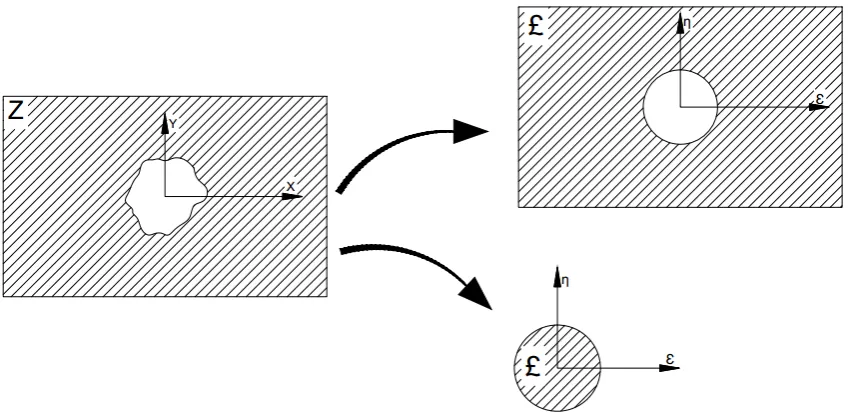
. The problem is solved using two complex potential functions. Finally, the resulting equations for the distribution of stresses or displacements are inverted to obtain those for the actual problem in the z-plane[8].Herein, the problem refers to the determination and optimization of appropriate conformal mapping functions to transform an infinite plane weakened by a tunnel with arbitrary cross section into a problem with simpler geometry for further stress and displacement analysis. Mapping functions also convert a set of tunnel and infinite plane to a circular disc or, as with unit diameter or, as another alternative, an infinite region weakened by a circular tunnel, as shown in Figure 1, to decrease the level of complexity involved in developing a closed form solution.
On the other hand, in the mapping functions, numbers of real and imaginary coefficients as well as their values control the geometry of the original problem. Thus, two methods have been introduced to optimize functions for tunnels with different cross sections.
3. The solution method 3.1. Conformal mapping
The conformal mapping functions used in this study is a method of conjugate trigonometric series [7]. The mapping function which conformally transforms the infinite region surrounding the hole onto the interior of the unit disc is of the following form:
1
1
( )
,
1
N k k k
z
R
(1)where R is a real constant that scales the shape and the complex coefficients appearing in Equation 1 are:
,
1, 2,...,
k
a
kib k
kN
(2)It can be easily verified that the circle
1 corresponds to the boundary of tunnel. The infinity in thez
plane
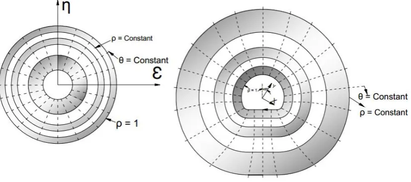
is mapped onto the origin of the unit circle, as shown in Figure 2.Figure 1. original and conformally mapped regions
Fig. 2. Conformal mapping of an infinite region surrounding a hole onto a unit circle
The values of real and imaginary parts of these coefficients determine the shape of the hole, which must be a simple closed curve. When the coefficients are selected properly according to the approaches presented hereafter, the coordinates of the points in the
region surrounding the hole in the
z
plane
were obtained by setting
n
nexp(
ni
)
in Equation 1. After separation of real and imaginary parts ofz
x iy
, parametric equations become:
1
1
cos
cos sin
sin
sin cos
N N
N N
k N
N
N N
k
x R a N b N
y R a N b N
(3)By setting
1
in Equation 3, the parametric equations defining the boundary of the hole were obtained. Then it is possible to define some tunnel and cavern shapes widely used in mining and civil engineering if certain number of terms and their values are assigned to the coefficients of Equation 3 [10].3.2. Optimization of mapping function
As it was previously referred to in Equation 4, mapping function shall conformally convert the geometry of the original problem and its corresponding transformed geometry, herein a unit disc, in a new coordinates system. It should be noted that in these functions, the number of terms in the series expansion as well as their values control the accuracy and correctness of the produced geometry through those functions matched with the original geometry. This is of great importance since
been introduced to optimize the aforementioned mapping functions. One may presume the original geometry of tunnel cross section and its transformed shape as Figure 1. Mapping function is therefore of the form:
2 3
0
1 2 3 ...
n n
a
z a
a
a
a
(4)
On the circle boundary (
1,
z
x iy
) Equation 4 shall have the form:2 0 1 2 3
3 ...
i i i
i ni
n
x iy a e a e a e
a e a e
(5)
where
0
1
cos cos( )
N n i
N
x a
a n
According to Figure 1, one may consider that M points are required to identify the boundary of underground excavation and, on the other hand, these points are supposed to have corresponding pairs on the unit circle in the transformed coordinates. Replacing the
coordinates of these points in Equation 6, is as follows:
Taking Equations 7 into account, there are two possible ways to match the geometry of the original excavation and one mapping function produces: j is a constant or variable.
1 0
0
1
0
1
cos cos( ) ( 2, 3,..., )
sin sin( ) ( 2, 3,..., )
N
n n
N
j n j j
i N
j n j j
i
a x
a a n x j M
a a n y j M
(7)
The first approach deals with optimization, while j is constant. In this method, each point on the original boundary forms an angle
on the unit circle. Therefore, Equation 7 will form a linear equation system witha
n as its unknown vector. After performing some manipulations, it is obvious that the aforementioned equation system contains 2M1 equations andN
1
unknown variables. It should be noted that if M andN
are determined such that both numbers are the same, it means that the equation systemhas a direct solution and the obtained function passes through all points on the original geometry as its input data. However, this approach requires the least square method as its complementary part to yield an appropriate match for a given excavation boundary. Given that 2M1 is sufficiently greater than
N
1
, the system of Equation 7 shall be rewritten as:
pq
A
Xq
Rp
(
p
2
M
1,
q
N
1)
(8)
where
2 2 2 2
2 2 2 2
1 1 1 1
cos cos cos(2 ) cos( )
cos cos cos(2 ) cos( ) sin sin sin(2 ) sin( )
sin sin sin(2 ) sin( )
pq M M M M
M M M M
N
A N
N
N
(9)
and
0, 1,
2,...,
Tq N
X
a a a
a
(10)
1,
2,
3,...,
,
2,
3,...,
Tp M M
R
x x x
x
y y
y
(11)where only the vector
X
q is unknown. Using least square mean approach, one obtains1
T T
qp pq q qp p qq q q
q qq q
A A X A R B X C
X B C
(12)
In the following results, the Matlab programming language has been extensively used for different tunnel cross sections.
of equations is nonlinear, where iteration methods are to be employed.
In this approach, as mentioned above, the system of equations is nonlinear due to terms including
Sin n
j andCos
j . In order to solve this system of equations, one may assume:1 0 1
1 1
N N
n n
n n
a x a x a
(13)By substituting
a
0 in Equation 7, one obtains:
1
1 1
1
1 1
cos
cos
0,
2,3,...,
sin
sin
0,
2,3,...,
N N
j n j n j j
n n
N N
j n j n j j
n n
f
x
a
a
n
x
j
M
g
x
a
a
n
y
j
M
(14)As shown earlier, fjand gjare functions of
a
n and jthat shall become zero. To solve the equations above, initial values are presumed for parametersa
n and j to yieldj
f and gj. If the initial values selected for the aforementioned parameters satisfy the system of Equations 14, then they are desirable values. Otherwise, wide range for
n
a
and j are to be examined using iteration methods to satisfy Equation 14.4. Results And Discussion
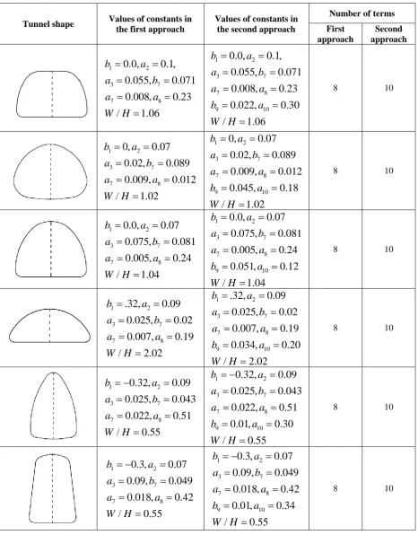
The number of terms and their values for different shapes of tunnel cross sections (Fig. 3), are depicted in Table 1. A close examination of the shapes and corresponding coefficients revealed that the value of
b
1 controls the width-to-height ratio
W H/
of the hole [3]; for example, forb
1
0,
W
H
; forb
1
0,
W H
/
;and for
b
1
0,
W
H
which yields a circle.Also, the value of
a
2controls the trigonometry of the tunnel shapes; for example fora
2
0
, the roof is wider than the floor, and fora
2
0
, the cross section becomes symmetric with respect to the horizontal axis. Similarly, coefficientsa
7and8
a
are responsible for the curvature radius of lower corners of the tunnel cross section. The more these coefficients increase, the lesscurvature radius the tunnel possesses. Coefficient
b
7also takes control of tunnel curvature at the crown; for example,b
7
0.07
the crown of the tunnel is flat and for
7
0.07
b
the crown takes a parabolic shape. Coefficientsb
9anda
10also control the accuracy of points by mapping function so far. As stated earlier, two methods have been put into the programming code showing that 10 coefficients yield the least amount of error between real tunnel shapes and prescribed ones. It should also be noted that the first and second approaches introduce, respectively, 8 and 10 coefficients. Having employed Equation 1, the symmetry axis of the opening makes an angle of4
with theOy axis in a counterclockwise sense. In fact, this is an awkward position to consider. Furthermore, the following formula for rotation of the axis of symmetry of tunnel with respect to
Oy axis
by4
is introduced into Equation 4:
exp
4
Table 1. Coefficients and their values in conformal mapping for different shapes
Tunnel shape Values of constants in the first approach
Values of constants in the second approach
Number of terms First approach Second approach 1 2 3 7 7 8
0.0,
0.1,
0.055,
0.071
0.008,
0.23
/
1.06
b
a
a
b
a
a
W H
1 2 3 7 7 8 9 100.0,
0.1,
0.055,
0.071
0.008,
0.23
0.022,
0.30
/
1.06
b
a
a
b
a
a
b
a
W H
8 10
1 2 3 7 7 8
0,
0.07
0.02,
0.089
0.009,
0.012
/
1.02
b
a
a
b
a
a
W H
1 2 3 7 7 8 9 100,
0.07
0.02,
0.089
0.009,
0.012
0.045,
0.18
/
1.02
b
a
a
b
a
a
b
a
W H
8 10
1 2 3 7 7 8
0.0,
0.07
0.075,
0.081
0.005,
0.24
/
1.04
b
a
a
b
a
a
W H
1 2 3 7 7 8 9 100.0,
0.07
0.075,
0.081
0.005,
0.24
0.051,
0.12
/
1.04
b
a
a
b
a
a
b
a
W H
8 10
1 2 3 7 7 8
.32,
0.09
0.025,
0.02
0.007,
0.19
/
2.02
b
a
a
b
a
a
W H
1 2 3 7 7 8 9 10.32,
0.09
0.025,
0.02
0.007,
0.19
0.034,
0.20
/
2.02
b
a
a
b
a
a
b
a
W H
8 10
1 2 3 7 7 8
0.32,
0.09
0.025,
0.043
0.022,
0.51
/
0.55
b
a
a
b
a
a
W H
1 2 3 7 7 8 9 100.32,
0.09
0.025,
0.043
0.022,
0.51
0.01,
0.30
/
0.55
b
a
a
b
a
a
b
a
W H
8 10
1 2 3 7 7 8
0.3,
0.07
0.09,
0.049
0.018,
0.42
/
0.55
b
a
a
b
a
a
W H
1 2 3 7 7 8 9 100.3,
0.07
0.09,
0.049
0.018,
0.42
0.01,
0.34
/
0.55
b
a
a
b
a
a
b
a
W H
Transformation of Cartesian coordinates through the parametric Equation 3, after their correction according to Equation 12, will result in a new orthogonal system of coordinates (Fig. 2b) that corresponds to the families of curves
constant and
constant in the
plane
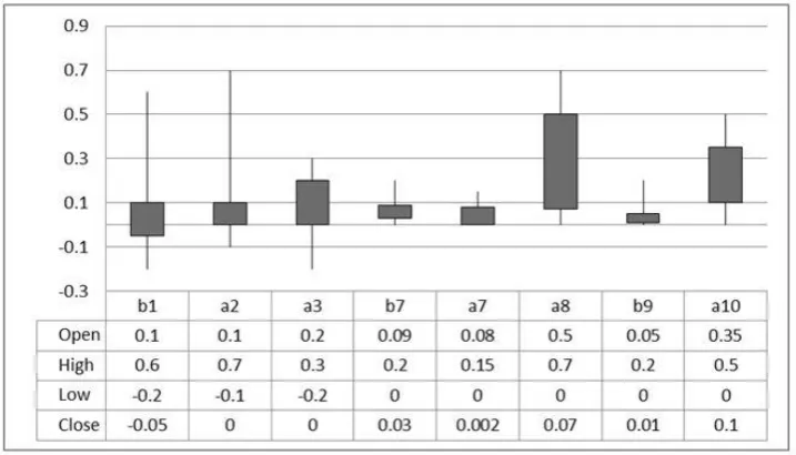
(Fig. 2b). It is noted that other values not mentioned in the table are considered to be zero. Since a combination of different values of the aforementioned coefficient, introduces a wide range of tunnel cross sections, Figure 3 shows the variation interval for either coefficients to give conventional shapes of tunnel cross sections widely used in tunneling practice.As earlier mentioned, curvature radius of tunnel cross sections at different positions is found to be controlled by coefficients
a a b
7,
8,
7. After execution of computer program containing both methodsfor broad range of shapes, the correlation between tunnel boundary curvatures and the corresponding coefficient values has cast light on the fact that these parameters play the leading role in giving a tunnel cross section the curvature of interest.
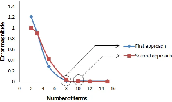
In Table 2, different curvatures have been represented by a variety of coefficient combinations. On the other hand, considering the magnitude of error for the two proposed methods representing tunnel shapes, it follows that 8 and 10 terms for the first and second methods, respectively, give acceptable accuracy for shapes generated by mapping function as shown in Figure 4. It is noted that the error function may be defined as difference between
(
x
y
)
summation of all points concluding the original tunnel boundary and those generated by mapping function.Fig. 3. Variation interval of coefficients for tunnel shapes with arched roof and floor
Table 2. Relation between tunnel curvature radius and coefficients
Tunnel curvature radius a7 a8 b7
In the
z
plane
, each point coordinates, lets sayx
y
, have been added up with the entire points and the resulting summation was compared with the summation resulting from the tunnel shapes generated by conformalmapping function for both methods. Based on this comparison, as shown in Figure 4, the first method may reach an extremely low error magnitude of 0.0186 for 8 terms while more terms make no significant difference so far.
Fig. 4. Correlation between the optimum number of terms in mapping function and error magnitude
On the other hand, for the second method, the magnitude of error reached 0.0083 for 10 terms, substantiating that the second approach has more potential of accuracy and tendency to converge to zero. Considering 10th terms onward, there is no considerable difference in error magnitude; thus, 10 terms have been considered as optimum number of terms for the second approach.
5. Conclusion
Two new methods to derive and optimize mapping functions, used in stress/displacement analysis of underground structures, are introduced as follows:
Analytical approaches have been developed to optimize the generated shapes by mapping function to have the least inconsistency with those of original tunnel shapes. That is, since the mapping functions are of series type with a limited number of constants, they never reached the exact expected geometry. The Matlab program has been used to determine the number of terms in each approach, using sensitivity analysis to produce good match original and mapped shapes.
On the other hand, it has been proven that certain coefficients have full control over special features of tunnel shapes such as height to width ratio and lower and upper
curvature radii. It has also been shown that certain interval of variation is valid for each coefficient enabling the produced tunnel shapes to represent common tunnel cross section in tunneling practice. However, more research on the interval of variation needs to be done to fully understand the accuracy of the solution.
Reference
[1] J. T. Chen, M. H. Tsai, and C. S. Liu, "Conformal mapping and bipolar coordinate for eccentric Laplace problems," Computer Applications in Engineering Education, vol. 17, pp. 314-322, 2009.
[2] S. G. Lekhnitskii, "Elasticity theory of anisotropic bodies," ed: Nauka, Moscow, 1977. [3] G. N. Savin, Stress concentration around holes
vol. 1: Pergamon Press, 1961.
[4] A. Verruijt, "A complex variable solution for a deforming circular tunnel in an elastic half-plane," International Journal for Numerical and Analytical Methods in Geomechanics, vol. 21, pp. 77-89, 1997.
rectangular structures subjected to far-field shear stresses," Tunnelling and underground space technology, vol. 21, pp. 613-625, 2006. [7] H. Gerçek, "An elastic solution for stresses
around tunnels with conventional shapes,"
International Journal of Rock Mechanics and Mining Sciences, vol. 34, pp. 96. e1-96. e14, 1997.
[8] N. I. Muskhelishvili, Some basic problems of the mathematical theory of elasticity: Springer, 1977.
[9] G. Exadaktylos and M. Stavropoulou, "A closed-form elastic solution for stresses and displacements around tunnels," International Journal of Rock Mechanics and Mining Sciences, vol. 39, pp. 905-916, 2002.