Research Journal
Volume 11, Iss. 1, March 2017, pages 147–153
DOI: 10.12913/22998624/66501 Research Article
INFLUENCE OF THE PATH TYPE ON SELECTED TECHNOLOGICAL EFFECTS
IN THE TROCHOIDAL MILLING
Kamil Waszczuk1, Paweł Karolczak1, Magdalena Wiśniewska1, Maciej Kowalski1
1 Wrocław University of Technology and Science, Faculty of Mechanical Engineering, Łukasiewicza 5, 50-370 Wrocław, Poland, e-mail: [email protected], [email protected], [email protected]. pl, [email protected]
ABSTRACT
The article presents basic information about machining materials in hardened state – it particularly describes a method of the so called hard milling. The paper discusses strate-gies and methods in hard milling, presents trochoidal milling, its advantages and disadvan-tages. It also presents research methodology and effects which concerned determination of a tool path impact on selected technological effects after trochoidal milling of the groove.
Keywords: hard machining, trochoidal milling, tool path.
INTRODUCTION
Treatment of materials in the hardened state is an issue of many industrial and scientific works. Obtaining appropriate surface roughness and high dimensional and shape tolerances with si-multaneous acceptable tool life causes many dif-ficulties. Therefore, traditional method of treating elements made of hard materials is grinding. It allows to obtain satisfying technological effects. Unfortunately, high energy consumption and ne-cessity to use large amount of liquids decreases profitability of this method.
A problem of rapid cutting blades’ wear while machining materials in hardened state can be eliminated by applying electroerosion machining, both EDM (Electrical Discharge Machining) and WEDM (Wire Electrode Discharge Machining). However, these methods do not allow obtaining appropriate accuracies of elements [1].
Therefore, newer and better manufacturing methods of machining parts made from materials in hardened state are searched for. Currently, the best alternative is the so called hard machining HM [2]. A specific application of this method is produc-tion of molds and dies where materials such as: tool steel after heat treatment with hardness from 45
HRC to even 70 HRC are processed [3]. Hard ma-chining has numerous advantages in comparison to abrasive processing. The most important are: • reduction of setup time,
• significant reduction of machining time, • decrease of machines amount by removing
ex-pensive machines for finishing treatment, • possibility of using “complete processing”
through which an element can be done in one mounting, reducing processing time increas-ing accuracy [4].
Simultaneously, it is worth noticing that it is possible to obtain comparable surface rough-ness. Using hard milling eliminates basic fault of grinding – using machining liquids. This is due to intermittent work of milling cutters. The presence of fluids when circular blades work can cause thermal shock and blades cracking. High temperatures occurring during hard milling cause that most of coolants turn into steam [5].
MILLING CUTTERS USED IN HARD
MACHINING
In order to fulfil requirements of hard milling applying appropriate milling cutters is required. Received: 2016.12.15
abrasion resistance but also be resistant to high temperatures and oxidation, especially while hard working conditions connected with high machin-ing parameters. Therefore, machinmachin-ing of hard ma-terials requires special properties, not only for tool materials but also for protective coatings. High temperatures that occur locally on the cutting edge in exceptional cases may cross over the melting point of the machined material. That is why it is so important to use extremely beneficial thermo-phisical properties of tool edge coatings allowing a reduction of heat load of the tool. Furthermore, coatings used in such cases must have stable prop-erties in the range of high temperatures and mark a particularly high resistance for oxidation [5, 6].
An increase in hardness of machined mate-rial causes significant increase in cutting force re-sistance and decrease in machining stability. It is necessary to appropriately design tool geometry that will be used in hard machining. In this type of tools, clearance angle is not decreased and at the same time reduced rake angles are applied (in some cases even negative angles).
The most commonly used mills in hard milling are:
• 4-blade (or more) mills which allow for ma-chining with higher feeds,
• torus end mills – their advantage is high stabil-ity in deep milling,
• mills with irregular flutes inclination – appli-cation this kind of flutes in combination with variable angle reduces vibration occurrence which provides higher reliability and longer cycle to tool replacement,
• high precision mills.
TROCHOIDAL MILLING
In planning hardened materials treatment, a proper design of tool path is an important is-sue. Milling tool should work according to such a trajectory which will enable decrease impact load and influences positively to arising
techno-• tool life increase by wear reduction,
• minimizing sudden changes in machining di-rection.
One of methods fulfiling this demands is tro-chidal milling. Trochoidal milling appears also as a TPC term (Trochoidal Performance Cutting) and is defined as circular milling with simultane-ous forward movements (example of generated path Fig. 1).
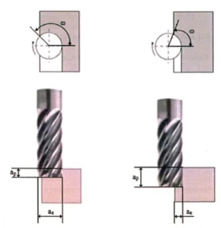
Different types of trochoid are distinguished. Their names depend on two factors: distance of the point from center of rolling circle and rela-tive position of the moving circle and the circle stable on the plane. If the rolling circle is inside constant circle, then the trochoid name starts with the hypo prefix (hypocycloid, hypotro-choid). But if the moving circle moves along the outside of fixed circle name starts with the epi prefix (epicycloid, epitrochoid). A characteris-tic feature of this method is increasing the mill-ing depth while decreasmill-ing the millmill-ing width (Fig. 2). As a result of such a tendency the arc
of engagement is decreasing, which is an angu-larly expressed part or a circuit being in contact with the machined material at any point in time.
Advantages of trochoidal milling are: • mild change of direction and milling forces, • lower tool wear,
• tools work with entire working length – milling cutter wears more evenly and proportionally, • favourable resultant milling force location [5, 8].
Trochoidal milling is not deprived of defects, which include:
• unfavorable chip removal, particularly in mill-ing pocket-type elements,
• long time of tool movement with working feed outside material, which increases processing time,
• difficult cooling of tool because of large im-mersion of tool in the processed material, • complex servo drive work resulting reduction
of actual feed [8, 10].
RESEARCH METHODOLOGY
The aim of researches was to determine influence of type of tool motion path on selected technological effects in trochoidal milling groove in hardened ma-terial. Investigated material was steel C 45 (1.0503) in hardened state. Its hardness was 50 HRC. For re-search two milling cutters (dedicated for hard ma-chining) with indication: 130100-MEGA-64 (Seco
Fig. 2. Comparison of the idea of conventional and trochoidal milling, where: ap – milling depth,
ae – width of cut, ω – tool arc of engagement [9]
Fig. 3. Machining center Hermle C600
Fig. 4. Paths used in research: type A- flattened trochoid, type B - quasi-trochoid, type C - bevelled
trochoid
tools with five blades) and EC-H7 10-20C10CF-M72 (Iscar with seven blades) were used.
The research was carried out on CNC ma-chining center Hermle C600 (Fig. 3). Each of the chosen tools was used for making a groove using three different tool movement trajectories. The paths were written manually. Figure 4
illus-A)
B)
• spindle speed n = 2570 [rpm].
In contrast feed rate was changing depending on tool type:
• SECO: vf = 771 [mm·min-1],
• ISCAR: vf = 900 [mm·min-1].
In the process of research the chips were col-lected. After milling process surface roughness of walls and bottom of the grooves were measured.
RESEARCH RESULTS
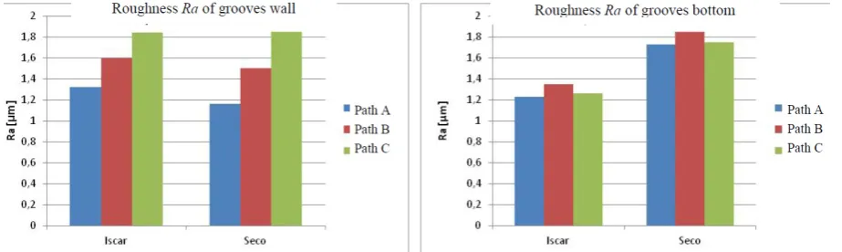
Figure 5 shows the results of measurements of the surface roughness Ra of grooves walls and bottoms. Analyzing the obtained results it can be concluded that there is a relationship between tool path and roughness of grooves wall. The lowest value of Ra parameter, both after milling Iscar and Seco tool, was obtained on groove wall milled along path A. After using path C the biggest values of Ra parameter was obtained. Differences between those surfaces are significant and have a value of 45%. Existence of influence of applied tool path on grooves walls roughness can be ex-plained by the fact that dynamical machining, in different ways, reacts on a set trajectories of tool movement. Servo-drives have a different inertia and acceleration in the X and Y axes. Therefore, for each machine there is a need of individual
ap-were noticed.
Different results were obtained in grooves bot-toms. In this case no significant influence between chosen path and surface roughness were observed. It results from the fact that there are different dy-namic forces on mills face and other on mills cir-cumference. During a sudden change of direction (eg.: exit from the arch) circuital force causes tool deflection. Whereas axial force on the milling cut-ters face is the same at different positions in X and Y axes (in flat mode on machines table), thus slight influence of path on the groove bottom roughness. However, there is a dependence between tool and surface roughness. Significant (up to 40%) higher values of Ra parameter of grooves bottom were measured after milling with Seco milling cutter. This can be explained by a dif-ferent number of blades (7 – Iscar, 5 – Seco) and that the Iscar cutter has an irregular pitch of blades and blade sheer line at angle 37º. Tool design is considerably more “fitted” for trochoi-dal milling process.
Comparing grooves walls and bottoms rough-ness it was observed that for Iscar tool and path A the values are similar, but for path B and C lover Ra values were obtained for the bottom of the groove. For Seco milling cutter similar values of Ra parameter for wall and groove bottom were obtained for trajectory C. For other paths, better surface roughness was observed on groove walls.
The second parameter selected for the analy-sis was RSm parameter (Fig. 6). It was selected because of a constant value of trochoids pitch, which should make that parameter RSm for stable process will be nearly too constant function. This assumption was confirmed for grooves bottom. Values of RSm parameter for the surface achieved
with Iscar Cutter are close to each other of the ap-plied path. In the case of the surface generated with Seco cutter the effect of the applied path on RSm parameter of groove bottom is visible, but so small that it can be omitted.
Interesting results were obtained for grooves wall. Among surfaces obtained with Iscar cutter
Fig. 6. Influence of path type on surface roughness parameter RSm grooves walls (left) and bottom (right)
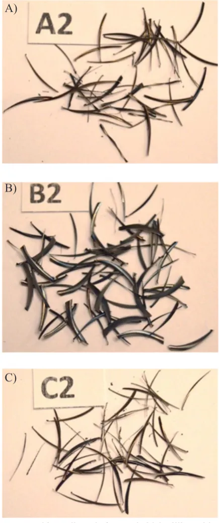
Fig. 8. Chips collected after trochoidal milling with Iscar cutter: A – flattened trochoid,
B – quasi-trochoid, C – bevelled trochoid
Fig. 9. Chips collected after trochoidal milling with Seco cutter: A - flattened trochoid,
B – quasi-trochoid, C – bevelled trochoid
A)
A)
B)
B)
tests are presented. Chips have a significant impact on the trochoidal milling process. They should not be blocked or cumulated in the cut-ting zone, but should remove heat appropri-ately. Analyzing the collected chips, it can be concluded that chosen motion path of the tool and tool itself does not significantly affect the form of chips (especially their thickness). All the collected chips can be classified as so called needle chips. This is a result compatible with theory. Average thickness depends, according to Formula 1, from the feed per tooth fz, milling width ae and tool diameter Dc. These param-eters were constant for both tools and for each of the paths.
c e z
m f Da
h = ⋅ (1)
hm – average chip thickness [mm],
fz – feed per tooth [mm],
ae – milling width [mm],
Dc – tool diameter [mm].
Furthermore, in each group of the collected chips a chip with shorted length and thickness but also somewhat bigger was observed. These dif-ferences are caused with the fact that chips came from different milling locations e.g.: from the entry or exit of milling cutter from the material. During experiments it was found that chips were carried out smoother during milling with 7 blade cutter (Iscar).
CONCLUSIONS
Milling is one of the main alternatives for abra-sive machining of materials in hardened state. The participation of milling in machining hard materi-als still grows. It is connected with greater possibil-ities of machines and tools. This participation will certainly grow along with optimization of milling strategies and refining tool movement paths dur-ing trochoidal milldur-ing. In work it was proven that important influence on the obtained technological effects of milled groove in material with a hardness of 50 HRC, have chosen a tool and its path. The number of milling cutter blades and regularity of blades pitch influence the roughness of the groove bottom. In the paper it was shown that milling cutters with irregular pitch and bigger quantity of blades give better effects. On roughness of grooves
wall large influence has motion path of tool. It is shown that the sharper motion path trajectory was the greater values of roughness parameter Ra was. It is related with inertia of the machine and in par-ticular with servo drives. In the article it was prov-en, according to theory, that the trajectory of tool movement path does not influence significantly on formed chips shape, under condition of unchanged basic machining parameters.
Trochoidal milling already is and will con-tinue to be the primary method of machining hard materials. Optimization of the process will certainly be aiming towards proper selection of a tools motion path trajectory for machining task and correlation of these factors with dynamic properties of a particular machine.
REFERENCES
1. Oczoś K.E., Dąbrowski L.: Obrabiarki elektro -erozyjne – stały wzrost walorów użytkowych, Mechanik, vol. 2/2006, 97–107.
2. Dąbrowski L.: Czy HSM wyprze EDM? Świat ob -rabiarek, vol. 11-12/2009, 14–18.
3. Siwiec J.: Obróbka materiałów w stanie utward -zonym, Mechanika – czasopismo techniczne, Wydawnictwo Politechniki Krakowskiej, 5 – M, 2011, vol. 15, 93–100.
4. Kawalec M.: Efekty technologiczne obróbki na twardo. Mechanik, volume1/2006, 20–25.
5. Oczoś K.E.: Obróbka wysokoproduktywna – wiodącym trendem obróbki skrawaniem, W: Red. Cichosz P.: Szkoła obróbki skrawaniem wysoka produktywność, Oficyna Wydawnicza Politechniki Wrocławskiej, Wrocław 2007, 31–50.
6. Stancekova, D.; Sajgalik, M.; Petru, J.; Naprst -kova, N.; Balaz, P.: Implementation of coating for failure elimination of dial gauges. In. METAL 2015: 24th international conference on metallurgy and materials, 2015, 1162–1169.
7. Iscar: Obróbka części tytanowych w lotnictwie przy użyciu zaawansowanych technologii do wydajnego usuwania materiału. Mechanik, volume 5-6/2012, 424–426.
8. Zalewski A.: Obróbka trochoidalna na frezarkach CNC. Mechanik, volume 4/2007, 303–304. 9. Waszczuk K., Socha K., „Frezowanie trachoidalne
– sposób obróbki ubytkowej materiałów w stanie utwardzonym”, Interdyscyplinarność badań nau -kowych 2015, Oficyna Wydawnicza Politechniki Wrocławskiej 2015, 257–256.
![Fig. 1. An example of generated tool path [7]](https://thumb-us.123doks.com/thumbv2/123dok_us/8807963.1775607/2.595.308.525.511.743/fig-example-generated-tool-path.webp)