KNX System Principles
KNX Bus Transceiver Application Module BAU T1 C1 T2 E1 Left II Left On Left II Right Off Left X Left Off Left X Right On Left II Left On Left II Right Off Left X Left Off Left X Right On a b c a b c Bus Cable ̓ E1‘ ̓ E2‘ Content
Content
Introduction
4Conventional system
5 1. Switch types 5 2. Building functions 6 3. Conclusions 7 4. What is the alternative? 7Bus system
81. Components 8 2. Working 8
3. Tool 9
Bus system advantages
121. Flexibility 12 2. Power separated from operation 12 3. Optimized cabling 12
4. Individual devices can have multiple functions 13
KNX specific advantages
141. Product certification 14 2. Saving energy 14 3. Making combinations 14 4. Decentralized bus system 15
Introduction
Introduction
During the last 50 years, science and technology have deve-loped in a swift manner. E.g. phones, with higher capacities than the computers used for the landing on the moon, are now considered as rather common. This technological evo-lution also propagated into the electrical installations of hou-ses and buildings, dealing with all sorts of applications, such as lighting, shutter control, HVAC, as well as security and ener-gy management.
Whilst conventional switching is still commonly used for the residential sector, the requirements and hence the comple-xity of those conventional installations escalate rapidly. Such further extensions require additional devices, like relays and timers and most of all additional wiring. Needless to say that commercial buildings, such as hotels and offices face even hig-her requirements and complexity, in order to accommodate the needs for each user. The answer, in order to realise all these automated functions without losing valuable time and invest in additional wiring, is building control with KNX® –
The worldwide STANDARD for home and building control.
Building control with KNX found its way into everyone’s life in the year 1990, at which actuators and sensors, each provi-ded with a microchip, are connected via a bus cable. The suc-cess of this new technology was determined by the possibility to control everything, which runs on electricity in a building as well as its flexible and easy configuration. Reprogramming instead of conventional rewiring opened a new dimension of managing electrical installations of houses and buildings, which allows to add, adjust, modify, change, repair, any room func-tion with – in a manner of speaking – just a few mouse clicks. Even in times of Smart Grids, where optimizing the use of re-newable energy has a key role, conventional installations play and will always play an important role for houses and buil-dings. This publication will bring you closer to how KNX in combination with this conventional technology, allows every owner to make an investment in sustainability and the future. Without any doubt, this publication will open your eyes to the fantastic world of building automation with KNX and will specifically teach you about the flexibility of building automa-tion with KNX.
Conventional systems
Conventional system
In order to explain the KNX system principles we should go way back in time: before the 80’s. Back then, most electri-cal installations in houses mainly controlled lighting, in some larger building also blinds were controlled with conventional electrical technology.
1. Switch types
Let’s have a look first at the three different conventional switch types in order to explain the working of conventional systems.
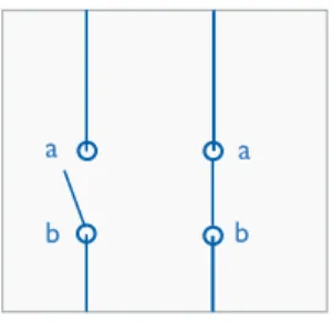
Simple switch
Simple switches have:
• two junctions: ‘a’ and ‘b’ – see Figure 1 • two positions:
• closed: junction ‘a’ is connected with junction ‘b’ • open: junction ‘a’ is not connected with junction ‘b’
a a
b b
Figure 1: simple switch
Figure 2: toggle switch
a a
c b
b c
Toggle switch
Toggle switches have:
• three junctions: ‘a’, ‘b’ and ‘c’ – see Figure 2 • two positions:
• left: junction ‘a’ is connected with junction ‘b’ • right: junction ‘a’ is connected with junction ‘c’
Cross switch
Cross switches have:
• four junctions: ‘a’, ‘b’, ‘c’ and ‘d’ – see Figure 3 • two positions:
• parallel: junction ‘a’ is connected with junction ‘c’ & junction ‘b’ with junction ‘d’ – see the left side circuit of Figure 3
• crossed: junction ‘a’ is connected with junction ‘d’ & junction ‘b’ with junction ‘c’ – see the right side circuit of Figure 3
Figure 3: cross switch
b d c a a c d b
Conventional building functions
2. Building functions
The actual conventional (building) functions are based on ventional switches. This clause gives an overview of such con-ventional functions, from most basic till most complex.
Single switch function
The most basic function type of a conventional electrical sys-tem is the single switch function; this function type can switch an electrical consumer from one operating point and is based on a conventional simple switch.
Figure 4 illustrates the working of a single switch function. The symbols ‘L’ and ‘N’ represent the conventional mains wires, ‘S1’ represents a conventional simple switch and ‘E1’ the elec-trical consumer, in this case a lamp.
Table 1 explains the correlation between the switch position and the status of the lamp:
• IF S1 is closed THEN the electrical circuit is closed, an
electrical current will flow and hence the lamp will be lit
• opening S1 again will interrupt the electrical current and the
lamp will no longer be lit
Figure 4: single switch
S1 E1 L N S1 E1 Open Off Closed On
Table 1: single switch
Double switch function
Suppose that two independent operating points are requi-red for lamp E1. Adding a second simple switch will not help here, because they cannot be operated independently: they both need to be closed in order to switch on the lamp (in any other combination the lamp would be switched off).
The solution is to use two conventional toggle switches. Figure 5 illustrates the working of a double switch function. The symbols ‘L’ and ‘N’ represent the conventional mains wi-res, ‘T1’ and ‘T2’ represent two conventional toggle switches and ‘E1’ an electrical consumer, in this case a lamp.
Table 2 explains the correlation between the switch positions and the status of the lamp:
• IF both T1 and T2 are put in the same position (either
both ‘left’ or both ‘right’) THEN the electrical circuit is closed, an electrical current will flow and hence the lamp will be lit
• putting T1 or T2 in opposite positions will interrupt
the electrical current and the lamp will no longer be lit
T1 T2 E1
Left Right Off
Left Left On
Right Right On Right Left Off
Table 2: double switch
Figure 5: double switch
T1
T2 L
N
E1
Multiple switch function
Suppose that x independent operating points are required for lamp E1. The solution is to add x-2 cross switches between two toggle switches. E.g. if x=7, then 5 cross switches need to be installed between 2 toggle switches (and the lamp its-elf of course).
Figure 6 illustrates the working of a multiple switch function. The symbols ‘L’ and ‘N’ represent the conventional mains wi-res, ‘T1’ and ‘T2’ represent two conventional toggle switches,
Conventional building functions
C1 . . . Cn
a b a b
c d c d
Figure 7: bus device 3. Conclusions
A first conclusion is that the functionality within a conventio-nal system is hardwired, i.e. the combination of the installed switch types and especially how these switches are wired to-gether, defines the functionality of an electrical installation. A consequence of this concept is that even the number of wi-res per control point needs to be planned, i.e. toggle switches require three wires and cross switches require four wires. The above is about the direct conclusions, but especially for larger buildings the indirect conclusions are actually even more important, their conventional electrical systems:
Figure 6: multiple switch
L T1 C1 . . . Cn T2 . . . N . . . L E1
Table 3: triple switch
T1 C1 T2 E1
Left Left On
Left Right Off
Left X Left Off
Left X Right On
Right Left Off
Right Right On
Right X Left On
Right X Right Off
I I I I
I I I I
• Have a complex, cumbersome, time consuming and thus
expensive cabling.
• Have an unfavorable functionality/cable ratio, i.e. they re
-latively require large cable quantities for little functionality (lighting).
• Are not flexible, adding e.g. one extra operating point
(switch) is very cumbersome.
• Have no separation between power and operation, i.e. con
-ventional switches control electrical consumers directly.
4. What is the alternative?
The best alternative is a bus system
The best alternative is called ICT, which is the abbreviation for Information and Communication Technology. Or better said the alternative to be more precise is a concept based on ICT. The three key aspects of this concept are:
• To replace ALL conventional switches (regardless of the
type) by push buttons being able to communicate or to
connect conventional push buttons / switches to interfaces
being able to communicate.
• To add to ALL electrical consumers (regardless of the type)
an interface being able to communicate or to control elec-trical consumers indirectly by switching devices being able to communicate.
• To link all devices being able to communicate via a dedicated
extra low voltage cable.
This concept is called a ‘Bus System’ and the cable linking the microcontrollers is called the ‘Bus Cable’ or short the ‘Bus’.
Bus system = collection of bus devices
The electronics for the communication is equipped with a mi-crocontroller which has on one hand an interface to the ap-pliance, e.g. operating elements, and on the other hand to the bus, see Figure 7:
• The composed electronics implementing the interface to
bus called ‘bus transceiver’.
• The composed electronics implementing the appliance called
‘application module’.
A device being connected to the bus and able to communica-te with other devices is called a bus device.
Conclusion – A (bus) device consists out of: • A microcontroller (µC)
• A bus transceiver • An application module
The combination of microcontroller and bus transceiver is called bus access unit (BAU).
KNX Application Module Bus Transceiver
BAU‘C1..Cn’ represents n conventional cross switches and ‘E1’ an electrical consumer, in this case a lamp.
A table explaining the correlation between the switch posi-tions and the status of the lamp can, depending on the num-ber cross switches installed between the two toggle switches, become quite big.
Such table can however be summarized as follows: the lamp will be lit:
• IF both T1 and T2 are put in the same position (either both
left or both right) AND given an even number of cross switches in crossed position
• IF T1 and T2 are put in opposite positions AND given an
odd number of cross switches in crossed position Any change will switch off the lamp again.
Table 3 explains the correlation between the switch positions and the status of the lamp for a multiple switch function whe-re only one crossed switch C1 is used (3 independent ope-rating points) and is a good illustration for the complexity of multiple switch functions.
Bus system
Bus system
This clause explains the working of a bus system step by step. Each such step explains one aspect of a bus system in general and at the same time a KNX system principle specifically, where applicable at least.
I. Components
Devices
A bus system is to be seen as a collection of bus devices. As just explained above, a KNX (bus) device consists out of a microcontroller, a bus transceiver and an application module. KNX devices can be divided into two groups: active devices and passive devices. Passive devices do not have ICT on-board, they ‘only’ have a supporting or indirect role; i.e. they do not communicate with other devices but are absolutely required in order to set up bus systems properly. Examples of passive devices are power supplies. Please note, that e.g. also power supplies could be extended with ICT, but this is not very common.
The other group, i.e. the active devices can be divided into the following device categories:
• Interfaces: their role is to connect a PC with a bus system
• Couplers: their role is to optimize the communication
effici-ency of bus systems
• Sensors: they contribute information to bus systems, e.g.
‘requested living room temperature = 22.5°C’
• Actuators: they link (conventional) electrical consumers with
bus systems, e.g. lamp connected to a lighting actuator out-put
About sensors & actuators
• Application modules of sensors typically convert analogue
signals or user actions, like:
• temperature
• push button rocker operations
• rain detection
• wind speed
• touch screen manipulations
• etc.
• Application modules of actuators are typically connected
with:
• an electrical consumer (e.g. a light ballast via relays)
• HVAC systems via valves
• etc.
• Application modules are electronically connected to mi
-crocontrollers.
How to convert a conventional system into a bus system
In this example, see Figure 8: a conventional triple switch func-tion is replaced by three sensors and one actuator:
• Each switch is replaced by a push button + bus access unit.
All by all these are three individual devices that belong to the same network.
• The electrical consumer is replaced by a relay + bus access
unit (+ the actual lamp of course). This is again an extra in
-dividual device that also belongs to the same network.
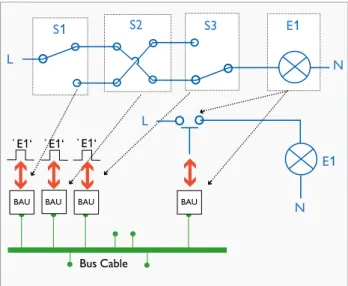
Figure 8: Converting a conventional system into a bus system 2. Working
Divided functionality
Figure 9 illustrates the divided functionality aspect of bus sys-tems:
The three sensors are located on the left hand side. Each of these sensors converts rocker manipulations into electro-nic pulses. Each such electroelectro-nic pulse represents an E1 user operation. The actuator is located on the right hand side and controls the relay connected to E1.
Figure 9: divided functionality of a bus system
S1 L S3 E1 N S2 N E1 L Bus Cable ̓ E1‘ ̓ E1‘ ̓ E1‘
Sensors Bus Cable N E1 L Actuator ̓ E1‘ ̓ E1‘ ̓ E1‘
BAU BAU BAU
BAU BAU BAU BAU
Bus system
Exchanging messages in order to link devices
The way sensors and actuators communicate in bus systems is by exchanging messages.
Example, see the above Figure 9: divided functionality of a bus system, suppose that the user manipulates one of the sen-sor rockers, this will induce an electronic pulse which will be processed by the microcontroller. The result is that the sen-sor will broadcast a message on the bus, here in this case the message is: ‘someone wants to operate E1’.
In KNX such message is called a telegram. A KNX sensor will in the above case send out a telegram with amongst others the following data:
• The ‘FunctionID’: here the FunctionID = E1
• The ‘FunctionValue’: here FunctionValue = 0 (switch off)
or FunctionValue = 1 (switch on)
All other sensors and actuators of the bus will receive this te-legram and process it:
• Sensors will simply ignore this telegram
• ONLY the actuators with the SAME FunctionID = E1 will react accordingly: i.e. switch on/off E1
Conclusion: in KNX, sensors and actuators are connected to-gether by exchanging telegrams, or in other words:
• In conventional systems operating elements and
electrical consumers are directly and physically linked via wires
• In bus systems operating elements and electrical
consumers are indirectly and virtually linked via messages exchanged between microcontrollers
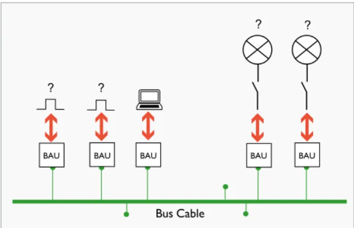
3. Tool
Bus systems = easy modifications
Making modifications to a bus system generally can be split into two separate tasks:
• Physically adding and/or removing and/or replacing devices • Modifying device functionality
The first part has already been addressed before, i.e. making modifications to the electrical part of a bus system is easy and
Figure 10: required = interface + computer + software tool
Bus Cable
? ?
? ?
moreover safe because of the extra low voltage wires. Also for actuators this is the case; they are typically installed in a cabi-net, i.e. safe and well hidden from any user of the installation. Please also note that possible modifications to the building structure (i.e. demolition work) are in most cases only re-quired for sensors and thus for extra low voltage cabling, because actuators usually are installed in cabinets.
Equipment required in order to modify bus systems
See Figure 10, the equipment required in order to modify bus systems is:
• A PC with a software tool onboard • An interface connecting the bus to a PC
The software tool for KNX is called ETS, which is the abbre-viation for Engineering Tool Software. Device functionality is stored into the memory of each device individually. In or-der to change the functionality of a device, its memory image needs to be modified, and exactly this is the role of ETS: chan-ging device memory.
Conclusion: modifying a KNX installation means reprogram-ming with ETS. Modifying a conventional system means rewi-ring, which again is a very cumbersome task.
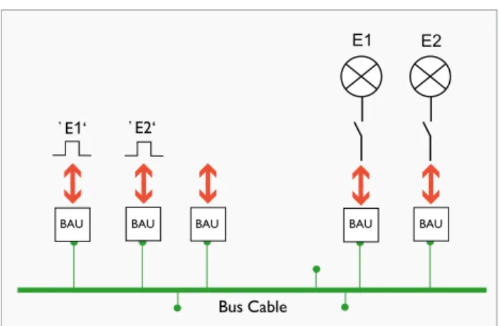
Bus system
Figure 11: Working with ETS is convenient
Bus Cable E1 E2 ̓ E1‘ ̓ E2‘
Working with ETS is convenient
See Figure 11, typical ETS tasks are:
• Fine tuning functionality: e.g. set up a stairway function for
the E2 actuator. Such stairway function will swith E2 auto-matically off after a while, this is convenient for residents of the building and it saves energy at the same time.
• Modifying functionality: e.g. make sure that a specific sen
-sor (operating point) no longer serves E1 but E2 instead.
• Adding functionality: e.g. an actuator already serving E1 shall
also serve E2 (given there is at least still one output chan-nel available).
• Extending existing functionality: e.g. add an extra sensor
(operating point) for E2.
A virtual link in KNX = Group Address
The following screenshots illustrate the true convenience of working with ETS.
But first this:
• Remember: in bus systems sensors and actuators
are virtually linked by exchanging messages.
• In KNX such message is called a Telegram.
• Each virtual link can be defined as a function identifier
representing one electrical consumer of the installation, like e.g. ‘E1’.
• In KNX such virtual link is called a Group Address.
Bus system
‘E1’ is the name of the Group Address = 0/0/1, this Group Address represents all de
-vices that are involved in this function. In the initial situation only two de-vices are pre-sent in the building function E1:
- One sensor, being device ‘1.1.10’ - One actuator, being device ‘1.1.100’ 2) Add more sensors for E1, see Figure 13
Figure 12: Initial situation, one sensor and one actuator in E1
Figure 13: Adding more sensors for E1
The sensors added are the devices ‘1.1.11’ till ‘1.1.19’.
Figure 14: Adding more actuators for E1
3) Add more actuators for E1: see Figure 14
And again: imagine doing the same with a conventional system, this reflection makes it really easy to understand the enormous potential of KNX installations.
The sensors added are the devices ‘1.1.101’ till ‘1.1.103’. 1) Intial situation, see Figure 12
Bus system advantages
Bus system advantages
1. Flexibility
The flexibility aspect is indeed the most important advantage of the bus concept. A comparison with a conventional mul-tiple switch function helps understanding this. See Figure 15 – e.g. n = 2. Suppose that one extra operating point for E1 needs to be added, i.e. one extra crossed switch (C3). As such this might look like a simple task but in practice it re-ally is not: remember that conventional systems have hardwi-red functionality: it is absolutely necessary to find out which wire goes where exactly, i.e. four low voltage wires in total need to be connected.With a bus system, the same task is much easier: just connect another sensor and make sure it is linked to the same FunctionID, see Figure 9: divided functio-nality of a bus system. The only requirement in order to add a sensor (or any bus device for that matter) is to make sure that it is properly connected to the bus, in case of KNX TP: just two extra low voltage wires need to be connected. Now imagine that the same task needs to be done for five, ten or even more operating points for E1. With a conventional sys-tem this will take hours or maybe even days, the time spent on the same task for a bus system is simply not comparable anymore, not to say neglectable. Please note that such action with a conventional system is not a very common practise, it is only to explain a principle.
Bottom line: with bus systems it is far more easier to:
• first of all create complex functions • to modify and/or to extend them.
2. Power separated from operation
This is a direct consequence of the divided functionality aspect:
• Sensors are connected to the bus via extra low voltage
(i.e. KNX TP = ~29 V) wires, the application modules (e.g. rocker) are connected to sensors via even lower voltages (3.3V or 5V).
• Actuators are also connected to the bus via extra
low voltage wires, the application modules (e.g. relay) operate in most cases low voltage consumers.
But actuators are typically installed in separate cabinets, i.e. safe and well hidden from any user of the installation. As such this might not look like a real advantage because it does not really change the functionality, the real advantage is the safety aspect: if anything would go wrong then in worst case the user is only exposed to extra low voltages, which in no way can cause any harm to human beings.
3. Optimized cabling
Cheaper cabling
This is a direct consequence of the flexibility aspect. Compa-red with conventional system, the following tasks can be done in no time:
• Adding devices • Removing devices • Replacing devices
Conclusion: easy cabling = faster cabling. Moreover: extra low voltage wires are thinner and are therefore easier to handle and install.
Higher functionality/cable ratio
The question here is: how much cable and hence copper is re-quired to set up the composed functionality of an entire elec-trical installation? Setting up e.g. a switch function with 20 con-trolling points in a conventional system takes tremendously more cable and hence more copper than for the same func-tion realized with a bus system. This comparison becomes even more impressive when looking at the entire installation, and certainly for bigger installations, like e.g. an office buil-ding with x floors. Moreover, until now only one application type, namely lighting, has been addressed: when also other ap-plication types, like blinds, HVAC, security, white goods, etc. need to be considered then a comparison between bus
sys-Figure 15: multiple switch
C1 . . . Cn a b a b c d c d N . . . T1 C1 . . . Cn T2 . . . L E1
Bus system advantages
Figure 16: Two separate actuators for E1 and E2
Figure 17: One actuator serving both E1 and E2
tems and conventional systems simply is no longer applicable: setting additional application types (like blinds) based on con-ventional system makes the job only more complicated, also it will again only take more cable. As such this might actually even be the most important argument for bus systems: in
or-der to add other building functions and/or building function types no parallel cabling is required, simple use and/or extend
the bus cable that is already in use.
4. Individual devices can have multiple functions
Actuators: serve more than one electrical consumer see Figure 16:
• One sensor sends telegrams for E1 on the bus • Another sensor does the same for E2
• One actuator serves E1 • Another actuator serves E2
In Figure 17 the situation is a bit different: now there is only one actuator serving both E1 and E2.
The advantages are:
• less bus cable (certainly for installation with thousands of building functions / bus devices)
• reduced number of devices
Sensors: combine functions and function types Figure 18: sensor serving both E1 and E4:
• E1 and E2 represent two light points • E3 and E4 represent two electrical motors
(e.g. E3 = blinds, E4 = garage gate)
• The sensor on the left hand side can send telegrams
both for E1 and E4
• One actuator serves both E1 and E2 • Another actuator serves both E3 and E4
Not only does this example illustrate that sensors can com-bine functions, it also points out that sensors can comcom-bine function types, here in this case:
• One rocker serving a lamp
• Another rocker serving e.g. blinds (electrical motor)
Moreover, also actuators can combine function types.
Figure 18: Sensor serving both E1 and E4
Bus Cable E1 E2 M ̓ E1‘ ̓ E4‘
E3 E4 M Bus Cable ̓ E1‘ ̓ E2‘ E1 E2
Bus Cable ̓ E1‘ ̓ E2‘ E1 E2
BAU BAU BAU BAU BAU BAU BAU BAU BAU BAU BAU BAU BAUMore KNX Advantages
KNX specific advantages
1. Product certification
KNX members can only bring KNX products on the market via the KNX product certification procedure, which means that the use of the KNX logo for a device is only granted af-ter a succesful certification procedure. The KNX logo prin-ted on each KNX device assures us of at least four aspects:
Quality
One of the prerequisites in order to apply for product cer-tification; is for the KNX member to be ISO 9001 compli-ant. This means that the KNX member needs to have a lity control system installed whitin its organisation. Such qua-lity control system will obviously have a positive influence on the quality and reliability of the KNX products manufactured by that KNX member.
Runtime compatibility
One part of the certifiction tests is to assure the compatibi-lity of the product under test. The result is manufacturer in-dependency: devices and applications of different manufactu-rers can be combined in an installation in any way and will wherever meaningful be able to communicate and under-stand each other.
Configuration compatibility
Another part of the certification tests is to assure the confi-guration compatibility of the product. The result is that only tool is required: i.e. any KNX device from any manufacturer can be configured with the KNX Engineering Tool Software, also known as ‘ETS’.
Backwards compatibility
KNX is and always will be backwards compatible: this means
that e.g. 20 year old installations can still be extended/equip
-ped with KNX devices brought to the market today. It also means that today’s installations can be extended with any KNX device brought on the market in the future.
2. Saving energy
Building events
Since the very beginning of KNX it is possible to adapt buil-ding loads automatically based on events occuring inside the building itself.
Example 1 – window contacts: i.e. the bus system of a
buil-ding can ‘know’ whether a window is open or closed. Now imagine an office building where the heating is set to comfort mode, if at the same time someone opens a window in one of the rooms of that building, then its installation can detect
this conflict and set the heating to e.g. economy mode in the room or in the zone where the open window was detected.
Example 2 – presence detection: the bus system of a
buil-ding can ‘know’ whether someone is present in a room, this will make it possible to only illuminate those rooms where also someone is really present.
Smart grids
KNX contributes to the Smart Grid concept: in the near fu-ture the connection between the electrical installation of a building and the energy provider will be extended with ICT, i.e. there will be an information flow in two directions: the information exchange from the provider to the building, is about the tariff of the energy supplied valid for that very time interval. The exchanged information in the other direction, is about the actual energy consumption of the building during that very time interval.
This concept will make it possible to adapt building loads auto-matically based on tariff. E.g. switch off loads with lower priori-ty when the energy, tariff reaches a particular price level. This does as such not necessiraly directly reduce our consumption of energy, but it will at least stimulate us e.g. to postpone the consumption of energy for lower priority loads till (more) re-newal energy is available. Result: reduced energy costs.
3. Making combinations
Building application types
With KNX it is possible to combine within one installation
all types of building functions, like: lighting, shutters/blinds, HVAC, metering, energy management, audio/video, white goods, access control, fire/smoke detection, physical sensors
(e.g. water) etc.
Communication media
First of all, KNX supports four different communication me-dia, they all serve a specific purpose or use case:
• TP: Twisted Pair, is the most common used solution, be
-cause of its simplicity in order to set it up (free topology, no network terminators required,…).
• PL: Powerline, which allows KNX devices to communica
-te over 230 V mains wires. This is of-ten the preferred so-lution for renovations.
• IP: typically used as a fast and reliable backbone between
several TP based segments of a KNX installation, this cer-tainly can be very important for bigger installations.
• RF: Radio Frequency, allows KNX devices to communi
-cate over radio signals, where no cable (TP, IP or PL) is available or cannot be installed.
Appendix
Second: all four communication media can be combined within one and the same KNX installation. In order to link two dif-ferent communication media, a so called ‘KNX Media Coup-ler’ is required: a few examples of possible combinations are
(primary medium/secondary medium): TP/RF, TP/PL, IP/TP.
4. Decentralised bus system
This means that the entire functionality of the installation is divided over the individual bus devices that form together the installation, or in other words: each individual bus device is ‘only’ informed about its own specific role within the tion. This concept makes the flexibility aspect of KNX installa-tions complete: changing, adding or removing devices has only a minor influence on the composite installation functionality. Centralised bus systems have a central unit that controls the entire installation. The disadvantage is the complete lack of flexiblity: a problem with the central unit will effect the entire installation, in worst case the entire installation simply stops working. Or even just updating the central unit could in worst case compromise the entire installation.
Yet, though KNX does not require any central component,
central functions are possible, like one or more central visua-lisations, schedulers, a central clock, management stations etc.
This publication 'only' explained the KNX system principles. We recommend to read the 'KNX Basics' flyer, the 'KNX Handbook' and to use the KNX eCampus platform, which is accessible via your 'My KNX' account, in order to understand what happens live in a KNX installation, or in other words in case you are interested in the bits and the bytes.