Hermetic
Compressor
Service Handbook
Wholesale Distribution
North America
Hermetic Compressor
Service Handbook
Ann Arbor, MI 48108
Tecumseh Products Company has prepared this Service Handbook to assist service personnel in
safely installing and servicing refrigeration and air conditioning equipment. The information in this
Service Handbook is generally limited to the compressor and to items and conditions affecting the
installation, operation, and servicing of the compressor. It is not designed to be a textbook or to
replace the training required for professional service technicians. Also, it is not intended to replace
other information available from the refrigeration and air conditioning system manufacturers.
Introduction 2
Trained Personnel Only 2
Terminal Venting and Electrocution 2
Refrigerants and Other Chemicals 4
Compressor Removal 4
System Flushing, Purging, and Pressure Testing for Leaks 4
System Charging 5
Prevention of Water-Utilizing System Explosions 6
Start Capacitor Overheating 7
System Evacuation 7
Follow the Labels 8
Model and Application
9Compressor Model Number Codes 10
Condensing Unit Model Number Codes 11
Serial Label Information 12
Basic Application Information for Hermetic Compressors 13
Compressor Motor and Component
15Single-phase Compressor Motor Types 16
PSC Motor Starting 17
Hermetic Compressor Thermal Protectors 19
Compressor Motor Starting Relays 21
Selecting Capacitors 24
Identification of Terminal Pins 26
Servicing
29Introduction to Servicing 31
Think Safety... 31
Before Servicing 31
Servicing or Troubleshooting Water-utilizing Systems: Preventing Explosions 32
Troubleshooting Chart 34
Installation and Replacement 73
Compressor Tube Connections 74
Refrigerant Line Sizes 76
Service Valves 82
Processing the System 82
System Cleanup and Compressor Replacement After Compressor Failure 83
Replacing Compressors in Water-Utilizing Systems: Preventing Explosions 87
Operation
89Control of Liquid Migration to the Compressor During Shutdown 90
Crankcase Heaters 93
Starting a System with Liquid Refrigerant in the Compressor 94
Control of Liquid Refrigerant Floodback to the Compressor During Operation 95
Accumulator Selection 98
Internal Pressure Relief Valves 99
Appendix
101The Basic Refrigeration Cycle 102
Example of a Tecumseh Hermetic Compressor 104
Reciprocating Compressor 105
Capillary Tube Sizing 106
Approved Hermetic Compressor Oils 108
Notes 110
Chapter 1
General Service
Safety Precautions
Introduction
Tecumseh Products Company has prepared this handbook to assist service personnel in safely working with refrigeration and air conditioning equipment that uses Tecumseh Products Company hermetic compressors. It is not designed to replace the training required for professional service personnel. It is also not intended to replace other information available from refrigeration and air conditioning equipment manufacturers.
Trained Personnel Only
Servicing, repairing, and troubleshooting refrigeration and air conditioning systems should be done only by those with the necessary knowledge, training, and equipment.
Terminal Venting and Electrocution
Improperly servicing, repairing, or troubleshooting a compressor can lead to electrocution or fire due to terminal venting with ignition. Follow the precautions below to avoid serious injury or death from electrocution or terminal venting with ignition.
Fire Hazard from Terminal Venting with Ignition
Oil and refrigerant can spray out of the compressor if one of the terminal pins is ejected from the hermetic terminal. This “terminal venting” can occur as a result of a ground fault (also known as a short circuit to ground) in the compressor. The oil and refrigerant spray from terminal venting can be ignited by electricity and produce flames that can lead to serious burns or death. See figures 1-1 through 1-3 for details.Terminal Venting and Electrocution Precautions
To reduce the risk of electrocution or serious burns or death from terminal venting with ignition:
• Be alert for sounds of arcing (sizzling, sputtering or popping) inside the compressor. IMMEDIATELY GET AWAY if you hear these sounds.
• Disconnect ALL electrical power before removing the protective terminal cover. Make sure that all power legs are open. (NOTE: The system may have more
than one power supply.)
• Never energize the system unless: 1) the protective terminal cover is securely fastened, and 2) the compressor is properly connected to ground.
Figures 1-4 through 1-6 illustrate the different means of fastening protective terminal covers.
• Never reset a breaker or replace a fuse without first checking for a ground fault (a short circuit to ground).
An open fuse or tripped circuit breaker is a strong indication of a ground fault (also know as a short circuit to ground). Use only a megohmmeter (“megger”) or a Hi-Potential Ground tester (Hi-Pot) to check for a ground fault. A conventional ohmmeter will not reliably detect a ground fault under certain circumstances. See the Service Handbook for more informa-tion on checking for a ground fault. Also, always follow the megger or Hi-Pot manufacturer’s procedures and safety rules.
If a ground fault does exist, keep the power off. WARNING! To avoid electric shock, electro-cution, and terminal venting with ignition, do not energize a compressor that has a ground
!
WARNING
Never service, repair, or troubleshoot unless you are qualified to perform these functions.
Improper servicing can lead to serious injury or death from fire, electrical shock, or
fault. Mark and red tag the compressor to indicate that there is a ground fault. Do not recon-nect the power leads. Tape and insulate each power lead separately.
• Disconnect power before servicing. Always disconnect power before servicing unless
it is required for a specific troubleshooting technique. In these situations, use extreme caution to avoid electric shock.
FIGURE 1-1: Compressor with (1) protective cover and (2) bale strap removed to show (3) hermetic terminal.
FIGURE 1-2: Close up view of hermetic terminal show-ing individual terminal pins with power leads removed.
FIGURE 1-3: Close up view of hermetic teminal after it has vented.
FIGURE 1-4: Compressor with (1) protective cover held in place by (2) metal bale strap.
FIGURE 1-5: Compressor with (1) protective cover held in place by (2) nut.
FIGURE 1-6: Compressor with (1) snap in protective cover.
Refrigerants and Other Chemicals
Contact with refrigerant, mixtures of refrigerant and oil, or other chemicals can cause a variety of injuries including burns and frostbite. For example, if refrigerant contacts skin or eyes, it can cause severe frostbite. Also, in the event of a compressor motor failure, some refrigerant and oil mixtures can be acidic and can cause chemical burns.
To avoid injury, wear appropriate protective eye wear, gloves, and clothing when servicing an air conditioning or refrigeration system. Refer to your refrigerant supplier for more information. If refrigerant or mixtures of refrigerant and oil come in contact with skin or eyes, flush the exposed area with water and get medical attention immediately.
Compressor Removal
Failure to properly remove the compressor can result in serious injury or death from electrocution, fire, or sudden release of refrigerant and oil.
Follow these precautions when removing a compressor from a system:
• Disconnect ALL electrical power. Disconnect all electrical power supplies to the system making sure that all power legs are open. (NOTE: the system may have more than one power supply.)
• Be sure refrigerant is recovered before removing compressor. Attempting to remove the compressor before removing all refrigerant from the system can cause a sudden release of refrigerant and oil. Among other things, this can:
»cause a variety of injuries including burns and frostbite.
»cause a fire if a torch is used to disconnect tubing.
»expose the service person to toxic gas.
• To avoid serious injury or death, be sure to remove and recover all refrigerant before removing the compressor.
• Use a tubing cutter, not a torch. Use a tubing cutter to remove the compressor. A torch can cause even trace amounts of refrigerant to decompose and release toxic fumes. In addition, using a torch to remove the compressor can cause a fire. If you ignore this recommendation and use a torch, be prepared to extinguish a fire.
System Flushing, Purging, and Pressure Testing for Leaks
Failure to properly purge or pressure test a system for leaks can result in serious injury or death from explosion, fire, or contact with acid-saturated refrigerant or oil mists.
Follow these precautions when purging or pressure testing a system for leaks:
• Tecumseh discourages the use of flushing products and recommends the use of suction line filter-drier and proper oil changes. If the use of a flushing agent is absolutely necessary, follow the flushing agent manufacturer's instructions.
• To purge a system, use only dry nitrogen.
• When pressure testing for leaks, use only regulated dry nitrogen or dry nitrogen plus trace amounts of the serial label refrigerant.
• When purging or pressure testing any refrigeration or air conditioning system for leaks, never use air, oxygen or acetylene.
»Oxygen can explode on contact with oil.
»Acetylene can decompose and explode when exposed to pressure greater than approximately 15 psig.
»Combining an oxidizing gas such as oxygen or air, with an HCFC or HFC refrigerant under pressure can result in a fire or explosion.
• Use a pressure regulating valve and pressure gauges.
Commercial cylinders of nitrogen contain pressures in excess of 2000 psig at 70°F. At pressures much lower than 2000 psig, compressors can explode and cause serious injury or death. To avoid over pressurizing the system, always use a pressure-regulating valve on the nitrogen cylinder discharge (see Figure 1-7). The pressure regulator must be able to reduce the pressure down to 1 or 2 psig and maintain this pressure.
The regulating valve must be equipped with two pressure gauges:
»one gauge to measure cylinder pressure, and
»one gauge to measure discharge or downstream pressure. • Use a pressure relief valve.
In addition to a pressure regulating valve and gauges, always install a pressure relief valve. This can also be a frangible disc type pressure relief device. This device should have a discharge port of at least ½” MPT size. The valve or frangible disc device must be set to release at 175 psig (see Figure 1-7).
• Do not pressurize the system beyond 150 psig field leak test pressure.
When field testing a system for leaks, 150 psig is adequate test pressure.
• Disconnect nitrogen cylinder and evacuate the system before connecting the refrigerant container.
Disconnect the nitrogen cylinder and evacuate the system according to the equipment manufacturer's recommendations prior to charging the system.
System Charging
Failure to properly charge the system can result in serious injury or death from explosion or fire.
Follow these precautions when charging a system:
• Do not operate the compressor without charge in the system.
Operating the compressor without a charge in the system can damage the hermetic terminal. As always, to avoid serious injury or death from terminal venting with ignition, never energize the compressor unless the protective terminal cover is securely fastened.
• Use proper refrigerant.
Use only the serial label refrigerant when charging the system. Using a different refrigerant can lead to excess system pressure and an explosion. Use of a
refrigerant other than the serial label refrigerant will void the compressor warranty. • Do not overcharge a refrigeration or air conditioning system.
Overcharging a refrigeration or air conditioning system can result in explosion. To avoid serious injury or death, never overcharge the system. Always use proper charging techniques. Limit charge amounts to those specified on the system equipment serial label or in the original equipment manufacturer’s service information.
Overcharging the system immerses the compressor motor, piston, connecting rods, and cylinders in liquid refrigerant. This creates a hydraulic block preventing the compressor from starting. The hydraulic block is also known as locked rotor.
Continued supply of electricity to the system causes heat to build in the compressor. This heat will eventually vaporize the refrigerant and rapidly increase system pressure. If, for any reason, the thermal protector fails to open the electrical circuit, system pressure can rise to high enough levels to cause a compressor housing explosion.
Gauges To System Relief Valve Regulating Valve FIGURE 1-7
Dry nitrogen cylinder with attached pressure gauges needed for pressure testing for leaks and purging.
Prevention of Water-Utilizing System Explosions
In certain water-utilizing refrigeration systems, water can leak into the refrigerant side of the sys-tem. This can lead to an explosion of system components including, but not limited to, the com-pressor. If such an explosion occurs, the resulting blast can kill or seriously injure anyone in the vicinity.
Systems at Risk of Explosion
Water-utilizing systems that have single-wall heat exchangers may present a risk of explo-sion. Such systems may include:
• water source heat pump/air conditioning systems, and
• water cooling systems, such as icemakers, water coolers, and juice dispensers. Water-utilizing systems that have single-wall heat exchangers present a risk of explosion unless they have either:
• a high pressure cut-out which interrupts power to ALL leads to the compressor, or
• an external pressure relief valve.
How an Explosion Occurs
If the refrigerant tubing in the heat exchanger develops a leak, water can enter the refriger-ant side of the system. Water entering the refrigerrefriger-ant side can come in contact with live electrical connections in the compressor causing a short circuit or a path to ground. When this occurs, extremely high temperatures can result. The heat build-up creates steam vapor that can cause excessive pressure throughout the entire system. This system pres-sure can lead to an explosion of the compressor or other system components.
Service Procedures
In light of the risk of explosion, be especially alert for signs of water leaking into the refrig-erant side of the system. Whenever servicing or troubleshooting a water-utilizing system, always check to see if it has either a pressure relief valve or a high-pressure cutout as pre-viously described. If the system does not have at least one of these, DISCONNECT ALL ELECTRICAL POWER and look for indications that water has leaked into the refrigerant side of the system. These indications may include:
• Observation or a report of a blown fuse or tripped circuit breaker. • Signs that water has leaked to the outside of the system.
• Reports that the system has made gurgling or percolating noises.
• A history of loss of refrigerant charge without a leak being found in the system. NOTE: Common leak detection methods will not detect a water-to-refrigerant leak in the system’s heat exchanger(s).
• Observation of or a report of the compressor giving off an unusual amount of heat. If ANY of these indications are present, do the following checks to determine if water has leaked into the refrigerant side:
Step 1: Check for a Ground Fault (a Short to Ground)
Use only a megohmmeter (“megger”) or a Hi-Potential Ground tester (“Hi-Pot”) to check for a ground fault. A conventional ohmmeter will not reliably detect a ground fault under certain cir-cumstances. To check for a ground fault, use the procedure outlined on pages 40-41.
• If a ground fault does not exist, go to Step 2. • If a ground fault does exist, keep the power off.
WARNING! To avoid electric shock, electrocution and terminal venting with igni-tion, do not energize a compressor that has a ground fault. Mark and red tag the compressor to indicate that there is a ground fault. Do not reconnect the power leads. Tape and insulate each power lead separately. Proceed to Step 2. Do not replace the compressor or energize the system before performing Step 2. Step 2: Check for Water in the System
Once the compressor is cool to the touch, open the system process valve slightly to see if any water comes out of the system. WARNING! Opening the system process valve while the compressor is hot can cause severe burns from steam coming out of the valve.
If ANY water comes out of the process valve, the entire system must be replaced. See "replacing a Single-wall Water-utilizing System” below.
If water does not come out of the process valve, there is still a possibility that some water has leaked into the refrigerant side of the system. To address this possibility, determine if the system has a history of losing refrigerant charge without a leak being found or repaired. If you find ANY indication of a history of losing refrigerant charge without detection of a leak, this is a sign that refrigerant has leaked in the water inside the heat exchanger. The entire system must be replaced. See “Replacing a Single-wall Water-utilizing System” on page 33.
If you do not find any indication of a history of loss of charge without detection of a leak, you still need to install:
»a high-pressure cut-out which interrupts power to ALL leads to the compressor, or »an external pressure relief valve.
Also, if you found a ground fault in the compressor in Step 1, replace the compressor be-fore applying power to the system.
Start Capacitor Overheating
An overheated start capacitor can burst and spray or splatter hot material that can cause burns. Applying voltage to a start capacitor for more than a few seconds can cause the capacitor to overheat.
Check capacitors with a capacitance meter, and never check a capacitor with the power on.
System Evacuation
Never use a compressor to evacuate a system. Instead, use a high-vacuum pump specifically designed for that purpose.
Never start the compressor while it is under deep vacuum. Always break a vacuum with a mini-mum 2 psig refrigerant charge before energizing the compressor.
The compressor is cooled primarily by the flow of refrigerant. Running a system that is low on charge will reduce the life of the comperssor.
Failure to follow these instructions can damage the hermetic terminal. As always, to avoid seri-ous injury or death from terminal venting with ignition, never energize the compressor unless the protective terminal cover is securely fastened.
Chapter 2
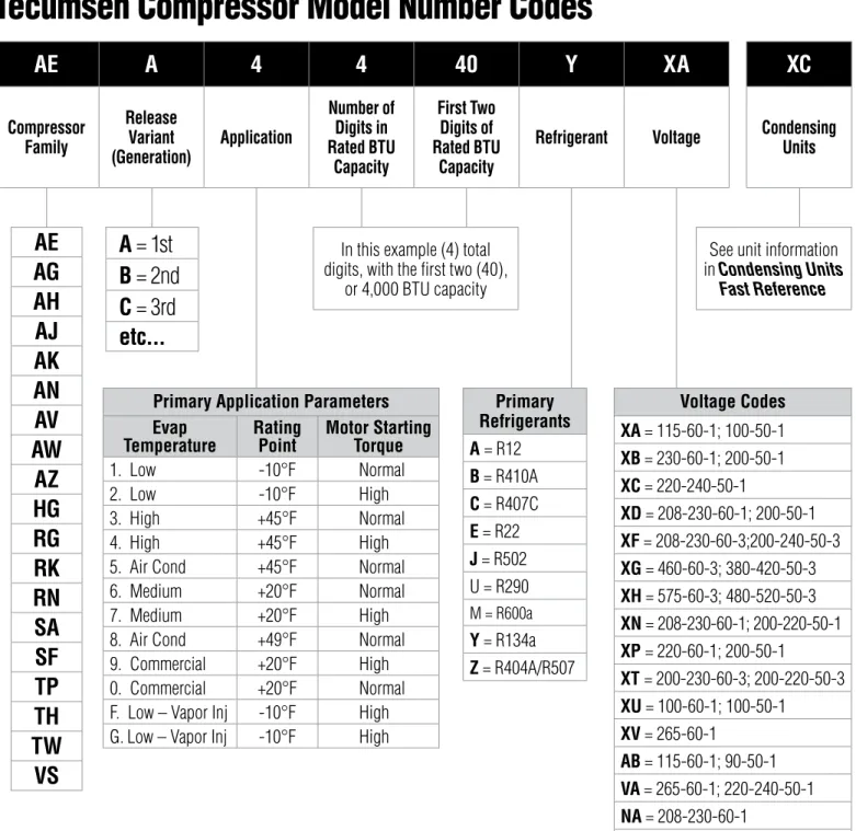
AE
A
4
4
40
Y
XA
XC
Compressor Family Release Variant (Generation) Application Number of Digits in Rated BTU Capacity First Two Digits of Rated BTU CapacityRefrigerant Voltage Condensing Units
AE
AG
AH
AJ
AK
AN
AV
AW
AZ
HG
RG
RK
RN
SA
SF
TP
TH
TW
VS
A
= 1st
B
= 2nd
C
= 3rd
etc...
Primary Application Parameters Evap
Temperature Rating Point Motor Starting Torque
1. Low -10°F Normal
2. Low -10°F High
3. High +45°F Normal
4. High +45°F High
5. Air Cond +45°F Normal
6. Medium +20°F Normal
7. Medium +20°F High
8. Air Cond +49°F Normal
9. Commercial +20°F High
0. Commercial +20°F Normal
F. Low – Vapor Inj -10°F High
G. Low – Vapor Inj -10°F High
In this example (4) total digits, with the first two (40),
or 4,000 BTU capacity Primary Refrigerants A = R12 B = R410A C = R407C E = R22 J = R502 U = R290 M = R600a Y = R134a Z = R404A/R507 Voltage Codes XA = 115-60-1; 100-50-1 XB = 230-60-1; 200-50-1 XC = 220-240-50-1 XD = 208-230-60-1; 200-50-1 XF = 208-230-60-3;200-240-50-3 XG = 460-60-3; 380-420-50-3 XH = 575-60-3; 480-520-50-3 XN = 208-230-60-1; 200-220-50-1 XP = 220-60-1; 200-50-1 XT = 200-230-60-3; 200-220-50-3 XU = 100-60-1; 100-50-1 XV = 265-60-1 AB = 115-60-1; 90-50-1 VA = 265-60-1; 220-240-50-1 NA = 208-230-60-1 AA = 115-60-1
See unit information
in Condensing Units
Fast Reference
Tecumseh Compressor Model Number Codes
NOTE: For explanation of compressor families and codes, contact Tecumseh Products Company.
A Standard Unit •
B Std. Unit W/Receiver Tank • •
C Std. Unit W/Receiver Tank & BX Cable • • •
D Std. Unit W/BX Cable • •
E,F,K Physical Design Variant (Conduit) • • •
G,H,J,L,P Physical Design Variant (Standard) • •
M Advanced Commercial Design • • • •
N Advanced Commercial Design • • •
S Customer Special •
T Interconnect Compressor •
U Water Cooled - Adv. Commercial Design • • • •
V Electrical Special (Conduit Design) • • •
W Water Cooled Unit • • •
X Interconnect Unit • • • •
Y Air Water Cooled Unit • •
Z Electrical Special (Standard Unit) • •
Evaporative Condensate Units Plastic Base
EC Large Evaporative Condensate Units Black Plastic Base •
ED Large Evaporative Condensate Units Black Plastic Base •
EE Large Evaporative Condensate Units Black Plastic Base •
GC Small - Fan Guard, Power Cord, Receiver Tank, Service Valves •
GB Small - Fan Guard, Power Cord, Receiver Tank •
GK Small - Fan Guard, Power Cord GL Small - Fan Guard
Outdoor Condensing Units
HL Outdoor Condensing Unit with Options • •
Celseon® Air Cooled Units
CB Std. Unit W/EC Fan Motor, Sweat Conns, Power Cord & Receiver Tank • •
CC Std. Unit W/EC Fan Motor, Sweat Conns, Power Cord, Receiver Tank & Service Valves • •
CK Std. Unit W/EC Fan Motor, Sweat Conns, Power Cord •
CS Std. Unit W/EC Fan Motor, Sweat Conns, Power Cord & Service Valves •
SB Std. Unit W/SP Fan Motor, Sweat Conns, Power Cord & Receiver Tank • •
SC Std. Unit W/SP Fan Motor, Sweat Conns, Power Cord, Receiver Tank & Service Valves • •
SK Std. Unit W/SP Fan Motor, Sweat Conns, Power Cord •
SS Std. Unit W/SP Fan Motor, Sweat Conns, Power Cord & Service Valves • The letters I, O, and Q are eliminated
In te rc on ne ct Co m pr es so r BX C ab le Re ce ive r Ta nk Ai r W at er Co ol ed W at er Co ol ed Fa n Co ol ed Se e B /M Ac cu m ul at or
Condensing Unit
Model Number Codes
E and G = Evaporative Condensate Units
S = Shaded Pole Fan Motor (Celseon)
C = Electrically Commutated Fan Motor (Celseon)
X = A holding character, reserved for future use H = Housed Unit
Condensing Unit Features, see chart below
AEA4440YXA XC
A H 3 0 1 F T - 0 7 7
SE1490C 281254 AH5540E V230/208HZ60 LRA103.0 V200 HZ50 PHI USA P
BILL OF MATERIAL NUMBER
SERIAL NUMBER
PHASE COMPRESSOR MODEL NUMGER ELECTRICAL RATING
VOLTS - HERTZ
SECOND LETTER INDICATES MONTH (SEE TABLE 2-1), NEXT TWO DIGITS INDICATE DAY OF MONTH, THE FOLLOWING 2 DIGITS INDICATE YEAR
Example of compressor serial plate FIGURE 2-3:
Follow the Labels
Tecumseh Products Company compressors have labels and markings with important informa-tion. For your safety and the safety of others, read the labels and markings on the product.
Serial Label Information
The only source for complete compressor information is on the compressor serial label. On earlier compressors, the serial plate is usually spot-welded on the upper housing of the compressor. For current compressors, the serial label is affixed in the same location. Both describe the character-istics of the compressor.
The months are identified in Table 2-1.
MANUFACTURING CODE DATE MONTH=SEPTEMBER
YEAR=2000 DAY = 24
THE LETTER REPRESENTS THE MONTH (SEE TABLE 2-1).
THE NUMBERS REPRESENT THE YEAR. J2400
Example of condensing unit serial label FIGURE 2-5:
ELECTRICAL RATING VOLTS - HERTZ - LRA - PHASE
COMPRESSOR MODEL NUMBER
LETTER INDICATES MONTH (SEE TABLE 2-1), NEXT 2 DIGITS INDICATE DAY OF THE MONTH, FOLLOWING 2 DIGITS INDICATE YEAR
Example of compressor serial label FIGURE 2-4:
Basic Application Information for Hermetic Compressors
Tecumseh hermetic compressors are engineered to do specific air conditioning and refrigeration tasks. Hermetic compressors are designed for a particular evaporator temperature range and a specific refrigerant.
Evaporator Temperatures
The key specification is the evaporator temperature of the system. Compressors that are operating outside their design evaporator temperature range can be expected to have poor pumping efficiency and experience motor problems.
Tecumseh hermetic compressors are designed for one of the following evaporator temperature ranges shown in Table 2-2.
Refrigerant
Use only the serial label refrigerant when charging the system. Using a different refrigerant can lead to excess system pressure, damage to the compressor and an explosion. For example, using R-404A in a compressor designed for R-134a can lead to higher operating pressures that can overload the bearings and overwork the motor. Use of a refrigerant other than the serial label refrigerant will void the compressor warranty.
Table 2-2: Evaporator Temperature Ranges
Application Approved Evaporator Temperatures
Air conditioning +32°F to +55°F
Improved performance air conditioning +32°F to +57°F
Heat pump (approved models) -15°F to +55°F
High evaporator temperature +20°F to +55°F
Medium evaporator temperature -10°F to +30°F
Low evaporator temperature
(normal torque motor) -10°F to +30°F
Low evaporator temperature
(high torque motor) -40°F to +10°F
Commercial 0°F to +50°F*
Low Evaporator Temperature - Vapor Injection
(high torgue motor) -40°F to +10°F
Low Evaporator Temperature - Liquid Injection
(high torque motor) -40°F to +10°F
*Some exceptions exist, contact Tecumseh Products Company
Table 2-1: Serial Label Month Identifiers
A – January D – April G – July K – October B – February E – May H – August L – November C – March F – June J – September M – December
Chapter 3
Compressor
Motor and Component
16
SERVICE HANDBOOKSingle-phase Compressor Motor Types
Tecumseh hermetic compressors contain motors designed for specific requirements of starting torque and running efficiency. There are four general types of single-phase motors, each dis-tinctly different from the others. Each type of motor may have two to four different configurations depending on the compressor components.
Resistance Start — Induction Run (RSIR)
This motor, also known as asplit-phase motor, is used on many small hermetic compressors up through 1/3 HP. The motor has low starting torque and must be applied to complete self-equalizing capillary tube systems such as household refrigerators, freezers, small water coolers, and dehumidifiers. This motor has a high resistance start winding which is not designed to remain in the circuit after the motor has come up to speed (see Figure 3-1). A relay is necessary to perform the function of disconnecting the start winding as the motor comes up to design speed. Three types of relays are used with this motor:
• a current relay,
• a wired-in Positive Temperature Coefficient (PTC) relay (see Figure 3-2), or
• a module Positive Temperature Coefficient (PTC) relay.
Capacitor Start — Induction
Run (CSIR)
The CSIR motor is similar to RSIR ex-cept a start capacitor is included in series with start winding to produce a higher starting torque (see Figure 3-3). This is commonly used on com-mercial refrigeration systems through ¾ HP. Two types of relays are used with this motor:
• a current relay, or
• a potential relay.
Capacitor Start and Run (CSR)
This motor arrangement uses a start capacitor and a run capacitor in paral-lel with each other and in series with the motor start winding (see Figure 3-4). This motor has high starting torque, runs efficiently, and is used on many refrigeration and air condi-tioning applications through 5 HP. ARSIR motor diagram with current relay
FIGURE 3-1:
RSIR motor diagram with wired-in PTC relay
FIGURE 3-2:
CSIR motor diagram FIGURE 3-3: Line 1 Line 2 Ground Control Relay - Current External Thermal Protector Star t Winding Main Winding Compressor - Unit Ground C S R 4 T M Thermal Protector
(115 Volt Only - Neutral) Line 1 Line 2 Ground Star t Winding Main Winding PTC Relay Compressor - Unit Ground
Alt. 3/4" Thermal Protector
Control
C
S
R
(115Volt Only - Neutral)
(115Volt Only - Neutral) Line 1 Line 2 Ground Control Relay - Current External Thermal Protector Start Winding Main Winding Compressor - Unit Ground S R C Start Capacitor Line 1 Line 2 Ground Control Relay - Current External Thermal Protector Star t Winding Main Winding Compressor - Unit Ground C S R 4 T M Thermal Protector Identified Conductor (115 Volt Only - Neutral) Line 1 Line 2 Ground Star t Winding Main Winding PTC Relay Compressor - Unit Ground
Alt. 3/4" Thermal Protector
Control C S R Line 1 Line 2 Ground Control Relay - Current External Thermal Protector Start Winding Main Winding Compressor - Unit Ground S R C Start Capacitor Line 1 Line 2 Ground Control Relay - Current External Thermal Protector Star t Winding Main Winding Compressor - Unit Ground C S R 4 T M Thermal Protector Identified Conductor (115 Volt Only - Neutral) Line 1 Line 2 Ground Star t Winding Main Winding PTC Relay Compressor - Unit Ground Alt. 3/4" Thermal Protector
Control C S R Line 1 Line 2 Ground Control Relay - Current External Thermal Protector Start Winding Main Winding Compressor - Unit Ground S R C Start Capacitor Line 1 Line 2 Ground Control Relay - Current External Thermal Protector Star t Winding Main Winding Compressor - Unit Ground C S R 4 T M Thermal Protector
(115 Volt Only - Neutral) Line 1 Line 2 Ground Star t Winding Main Winding PTC Relay Compressor - Unit Ground
Alt. 3/4" Thermal Protector
Control
C
S
R
(115Volt Only - Neutral)
(115Volt Only - Neutral)
Line 1 Line 2 Ground Control Relay - Current External Thermal Protector Start Winding Main Winding Compressor - Unit Ground S R C Start Capacitor
17
potential relay removes the start ca-pacitor from the circuit after the mo-tor is up to speed. This momo-tor may use either:
• an external thermal protector, or
• an internal thermal protector.
Permanent Split Capacitor
(PSC)
Here a run capacitor is in series with the start winding. Both run capacitor and start winding remain in the circuit during start and after motor is up to speed (see Figure 3-5). This normal starting torque motor is sufficient for capillary and other self-equalizing system. No start capacitor or relay is necessary. For additional starting torque, a proper start assist kit may be added (see Figure 3-6). Some start assist kits may include:
• a wired-in Positive Temperature Coefficient (PTC) relay, or
• a module Positive Temperature Coefficient (PTC) relay.
This motor may use either:
• an external thermal protector, or
• an internal thermal protector. PSC motors are basically air condi-tioning compressor motors and are very common up through 5 HP.
PSC Motor Starting
Tecumseh Products Company pioneered the development of Permanent Split Capacitor compressor motors. This type of motor elim-inates the need for potentially troublesome and costly extra electrical components, e.g., start capacitors and potential motor starting relays (see Figure 3-5).
To fully realize the capabilities of this simplified type of compressor motor, it is necessary to understand its starting and operating characteristics and the field conditions that can affect it.
The following conditions affect PSC motor starting:
• Low voltage: Reduces motor start-ing and runnstart-ing torque. A 10% voltage drop reduces a motor’s starting ability by 19%. Low volt-age can cause no start, hard start, light flicker, and TV screen flip flop.
PSC motor diagram with start assist kit that includes a module PTC relay FIGURE 3-6: CSR motor diagram FIGURE 3-4: PSC motor diagram FIGURE 3-5: Relay -Potential Compressor -Unit Ground Line 1 Line 2 Ground Start Winding Main Winding Control External or Internal Thermal Protector C S R Compressor -Unit Ground External or Internal Thermal Protector Run Capacitor Line 1 Line 2 Ground Star t Winding Main Winding Control C S R Line 1 Line 2 Ground Compressor -Unit Ground PTC Relay Plug-In Run Capacitor PTC Starting and Protector Package Thermal Protector Star t Winding Main Winding C C C2 C1 N S R
(115Volt Only - Neutral)
(115Volt Only - Neutral)
Relay -Potential Compressor -Unit Ground Line 1 Line 2 Ground Start Winding Main Winding Control External or Internal Thermal Protector C S R Compressor -Unit Ground External or Internal Thermal Protector Run Capacitor Line 1 Line 2 Ground Star t Winding Main Winding Control C S R Line 1 Line 2 Ground Compressor -Unit Ground PTC Relay Plug-In Run Capacitor PTC Starting and Protector Package Thermal Protector Star t Winding Main Winding C C C2 C1 N S R
(115Volt Only - Neutral)
(115Volt Only - Neutral)
Relay -Potential Compressor -Unit Ground Line 1 Line 2 Ground Start Winding Main Winding Control External or Internal Thermal Protector C S R Compressor -Unit Ground External or Internal Thermal Protector Run Capacitor Line 1 Line 2 Ground Star t Winding Main Winding Control C S R Line 1 Line 2 Ground Compressor -Unit Ground PTC Relay Plug-In Run Capacitor PTC Starting and Protector Package Thermal Protector Star t Winding Main Winding C C C2 C1 N S R
(115Volt Only - Neutral)
Minimum starting voltage for the compressor when it is attempting to start (locked rotor) is listed in Table 3-1.
• Unequalized system pressure: Head and suction pressures must be equal and not more than the pressures listed in Table 3-2. Refrigeration metering device (cap tube or TX valve) should equalize system pressure within 3 minutes. Unequal system pressure may be caused by excessive refrigerant charge, short cycling thermostat, or system restriction.
• Circuit breaker or fuse trips: Branch circuit fuses or circuit breakers sized too small will cause nuisance tripping (see “Fuse and Circuit Breaker Sizing” on page 27). If the fuse or circuit breaker trips, see “Identifying Compressor Electrical Problems” on pages 40-41 for electrical troubleshooting techniques.
• Electrical components: A failed run capacitor will not allow the compressor to start, and it will trip the thermal protector. See “Identifying Compressor Electrical Problems” on pages 40-41 for electrical troubleshooting techniques.
Table 3-1: Minimum Starting Voltage Serial Label Voltage Min. Voltage for Start
115 103
208 188
230 207
208/230 198
265 239
Table 3-2: Maximium Equalized Pressures
Refrigerant Maximium Equalized Pressures
R-410A 275 psig
R-22 170 psig
R-407C 180 psig
R-134a 104 psig
Hermetic Compressor Thermal Protectors
Hermetic compressor motors are protected from overheating by thermal protectors built into or mounted in contact with the compressor motor. See the Electrical Service Parts Guide Book for correct replacement thermal protectors.
When firmly attached to the compressor housing, the thermal protector device (See Figure 3-8) quickly senses any unusual temperature rise or excess current draw. The bi-metal disc within the thermal protector (see Figure 3-8) reacts to excess temperature and/or excess current draw by flexing downward and disconnecting the compressor from the power source.
Figures 3-9 and 3-10 show the installation of a thermal protector on an AE compressor. Table 3-2 lists useful information about thermal protectors.
FIGURE 3-7: External thermal protector. (Models AE, TP, TH, AK AJ, CAJ AZ, HG, RK, RG, RN, TW and some CL)
FIGURE 3-8: Bi-metal disc.
FIGURE 3-9: AE refrigeration compres-sor showing (1) hermetic terminal, (2) thermal protector, (3) thermal protector clip, (4) push-on relay, (5) protective ter-minal cover, and (6) bale strap.
FIGURE 3-10: AE refrigeration compressor with the thermal protector and relay assem-bled.
Table 3-3: Facts About Thermal Protectors
External Line-Break Thermal Protectors
• Currently used on all AE, AK, AZ, TP, TH, TW, HG, RK, RG, RN, and AJ models. • Sense motor current and housing temperature or combination thereof
• Break line current when tripped
• Generally do not protect against loss of charge
• When, by design, no air flow passes over housing, a special “static” thermal protector must be used
• Are designed for specific compressors and their intended application. Make no substitutions • Will not protect motor if compressor is operated outside its evaporator temperature range Internal Line-Break Thermal Protectors
• Currently used on all AH, AB, AV, AG, AW, VS and most AN, SA and SF models • Sense motor current and motor winding temperature or combination thereof • Break line current when tripped
• Generally protect against loss of charge
• Will not protect motor if compressor if operated outside its evaporator temperature range • Not repairable or replaceable
Line Voltage-Electronic Protection Module (note - for more specific details consult an authorized wholesaler)
• Originally used on some AN and SF models
• Employs use of solid state temperature sensors in motor windings and compressor discharge muffler
• Sensor resistance values change with temperature variations
• Module will interrupt power to the contactor coil when resistance values of sensors exceed the specified range. This power interruption thus stops the compressor motor
• Module provides protection against – Abnormal locked rotor conditions – Loss of refrigerant
– High compressor discharge temperatures – Excessive current conditions
– Time delays of 3 to 5 minutes occur on power interruption or sensor trip
Internal Thermal Protectors
Internal thermal protectors are completely internal and tamper-proof. They cannot be bypassed.
Single-phase Motor Thermal Protectors
Internal thermal protectors detect excess heat and/or current draw. They are located in the fol-lowing single-phase motors: AB, AW, AN, AH, AV, AG, and VS.
Three-phase Motor Thermal Protectors
The 31HM, 32HM, 34HM and 35HM on-winding motor protectors are 3-phase line break, au-tomatic reset devices wired in series with each phase at the neutral point and mounted on the windings. They are used in AB, AW, AN, AG, AV and VS models.
Compressor Motor Starting Relays
A hermetic motor starting relay is an automatic switching device to disconnect the motor start capacitor and/or start winding after the motor has reached running speed.
Never select a replacement relay solely by horsepower or other generalized rating. Select the cor-rect relay from the Tecumseh Electrical Service Parts Guide Book.
There are two types of motor starting relays used in refrigeration and air conditioning applications: the current responsive type and the potential (voltage) responsive type.
Current Type Relay
When power is applied to a compressor motor, the relay solenoid coil attracts the relay armature upward causing bridging contact and stationary contact to engage. This ener-gizes the motor start winding. When the compressor motor attains running speed, the motor main winding current is such that the relay solenoid coil de-energizes allowing the relay contacts to drop open thereby disconnecting motor start winding. The relay must be mounted in true vertical position so armature and bridging contact will drop free when relay solenoid is de-energized. See Figure 3-11.
PTC Type Relay
PTC type relay is a solid state current sensitive relay. Certain ceramic materials have the unique property of greatly increasing their resistance as they heat up from current passing through them. A PTC solid state starting device is placed in series with the start winding and normally has a very low resistance. Upon startup, as current starts to flow to the start winding, the resistance rapidly rises to a very high value thus reducing the start winding current to a trickle and effectively taking that winding out of operation. See Figure 3-12. Usage is generally limited to domestic refrigeration and freezers. Because it takes 3 to 10 minutes to cool down between operating cycles, it is not feasible for short cycling com-mercial applications.
Potential Type Relay
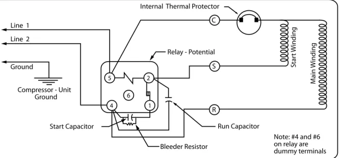
Potential type relays are generally used with large commercial and air conditioning com-pressors (capacitor start, capacitor run) to 5 HP. Relay contacts are normally closed. The relay coil is wired across the start winding and senses voltage change. Starting winding voltage increases with motor speed. As the voltage increases to the specific pickup value, the armature pulls up, opening the relay contacts, de-energizing the start winding capaci-tor. After switching, there is still sufficient voltage induced in the start winding to keep the relay coil energized and the relay starting contacts open. When power is shut off to the motor, the voltage drops to zero, the coil is de-energized, and the start contacts reset. See Figure 3-13.
When changing a compressor relay, care should be taken to install the replacement in the same position as the original. Table 3-4 lists useful information regarding starting relays.
FIGURE 3-12:
PTC Type Relay FIGURE 3-13: Potential Type Relay FIGURE 3-11:
Table 3-4: Facts about Starting Relays
Relay Type Compressor Motor
Type Characteristics
Current Relay RSIR and CSIR • Sense starting current to main (run)
windings
• Contacts normally open
• Contacts close and then release in less than 1 second as motor starts
• Must be installed vertically since con-tacts open by gravity
PTC Relay RSIR and PSC • Sense starting current to start winding
• Solid state device whose resistance in-creases with heat from current as motor starts
• Takes 3 to 10 minutes to cool down be-tween operating cycles
Potential Relay CSR • Sense voltage generated by start
wind-ing
• Contacts normally closed
• Contacts open in less than 1 second as motor starts
Potential Type Relay Supplier Code Designations
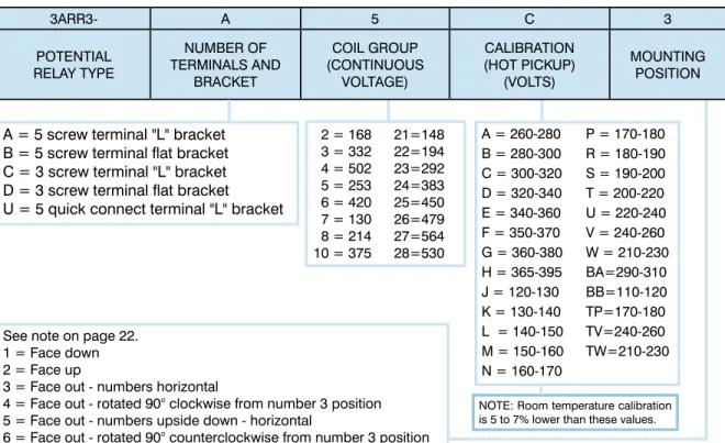
In recent years, Tecumseh has used an increasing number of potential relays with hermetic compressors. A large number of these have been used on air conditioning applications, but there are also many other applications. Since there are many variations with regard to these relays such as number of terminals, coil group, hot pick up, and mounting position, an explanation of the code numbers should be useful in the field.
Tecumseh has two major suppliers of potential relays: the General Electric Company and the White Rodgers Company. An explanation of the code designation for relays manufac-tured by each of these companies is provided in Figures 3-14 and 3-15.
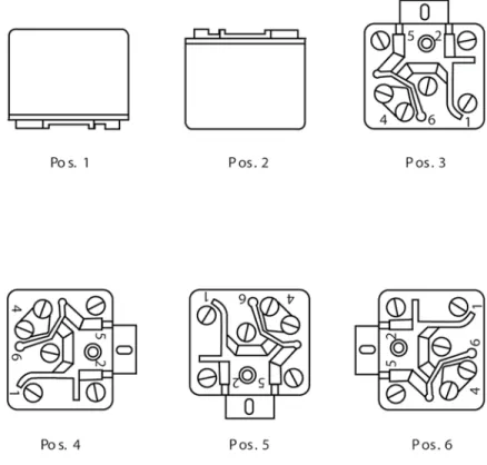
NOTE: The G.E. and White Rodgers relay model numbers indicate the position the relay is to be mounted. Refer to Figures 3-14, 3-15 and 3-16. It is of utmost importance that the relays be mounted in the required position. Mounting in any other position can change the relay’s operating characteristics enough so that the compressor will not start properly. This can result in compressor motor failure.
3ARR3- A 5 C 3 POTENTIAL RELAY TYPE NUMBER OF TERMINALS AND BRACKET COIL GROUP (CONTINUOUS VOLTAGE) CALIBRATION (HOT PICKUP) (VOLTS) MOUNTING POSITION 2 = 168 3 = 332 4 = 502 5 = 253 6 = 420 7 = 130 8 = 214 10 = 375 21=148 22=194 23=292 24=383 25=450 26=479 27=564 28=530
A = 5 screw terminal "L" bracket B = 5 screw terminal flat bracket C = 3 screw terminal "L" bracket D = 3 screw terminal flat bracket U = 5 quick connect terminal "L" bracket
A = 260-280 B = 280-300 C = 300-320 D = 320-340 E = 340-360 F = 350-370 G = 360-380 H = 365-395 J = 120-130 K = 130-140 L = 140-150 M = 150-160 N = 160-170 P = 170-180 R = 180-190 S = 190-200 T = 200-220 U = 220-240 V = 240-260 W = 210-230 BA=290-310 BB=110-120 TP=170-180 TV=240-260 TW=210-230
NOTE: Room temperature calibration is 5 to 7% lower than these values.
See note on page 22. 1 = Face down 2 = Face up
3 = Face out - numbers horizontal
4 = Face out - rotated 90° clockwise from number 3 position 5 = Face out - numbers upside down - horizontal
6 = Face out - rotated 90° counterclockwise from number 3 position
Example: 3ARR3-A5C3
FIGURE 3-14: Explanation of GE Potential Relay Code.
128- 12 2- 13 3 5 C A POTENTIAL RELAY TYPE TYPE OF BRACKET CONTACT STRUCTURE TERMINALS, TYPE AND LOCATION COIL GROUP (CONTINUOUS VOLTAGE) MOUNTING POSITION CALIBRATION (HOT PICK UP)
(VOLTS) CUSTOMER'S PART NUMBER (TO BE STAMPED ON RELAY) 1 = 130 2 = 170 3 = 256 4 = 336 5 = 395 6 = 420 7 = 495 2 = SPNC - less than 1½ HP 6 = SPNC - 1½ and larger 11 = 3 screw terminal
12 = 4 screw terminal (seldom used) 13 = 5 screw terminal
23 = 5 quick connect terminals
See note on page 22. 1 = Face down 2 = Face up
3 = Face out - numbers horizontal
4 = Face out - rotated 90° clockwise from number 3 position 5 = Face out - numbers upside down - horizontal
6 = Face out - rotated 90° counterclockwise from number 3 position 11 = Flat bracket remote (Tecumseh)
12 = "L" bracket (Tecumseh)
16 = "L" bracket for "FB" model compressors
20 = "L" bracket for Tecumseh Twins = 1½ HP and larger 21 = "L" bracket for capacitor box mounting
29 = Flat bracket (Marion) was "14" (under cover)
A = 260-280 B = 280-300 C = 300-320 D = 320-340 E = 340-360 F = 350-370 G = 360-380 H = 365-395 J = 120-130 K = 130-140 L = 140-150 M = 150-160 N = 160-170 P = 170-180 R = 180-190 S = 190-200 T = 200-220 U = 220-240 V = 240-260 W = 210-230 NOTE: Room temperature calibration is 5 to 7% lower than these values.
Example: 128-122-1335CA
Selecting Capacitors
Never use a capacitor with a lower voltage rating than that specified. A higher voltage rating than that specified is acceptable.
Start Capacitor Bleeder Resistors
Modern high power factor, low current single-phase compressor motors which required start and run capacitors used with potential type relays can created electrical circuits which could cause starting relay damage resulting in compressor failure.
The high voltage stored in the start capacitor could discharge across the contacts of the starting relay thus welding them and preventing the relay from functioning. Capacitor fail-ure and/or starting winding failfail-ure could result.
To eliminate this, Tecumseh Products Company start capacitors are equipped with bleeder resistors wired across the capacitor terminals. No start capacitor used in conjunction with a potential relay and run capacitor should be installed without such a bleeder resistor. In an emergency where no bleeder resistor equipped capacitors are available, a two watt 15,000 ohm resistor can be obtained and soldered across the capacitor terminals. See Figure 3-17.
Start Capacitor Substitution
If the specified start capacitor is not available, the next larger sized MFD capacitor at the same or higher voltage rating may be used. Do not add excessive starting capacitance.
Run Capacitors
Since January 1979, capacitors provided by Tecumseh have contained non-PCB oils or have been constructed using non-PCB impregnated metallized paper elec-trodes and polypropylene dielectric. These capacitors are protected against case rupture by a device within the capacitor can if failure occurs. The operation of this safety device could cause the terminal end to bulge outward ½”. Suitable head space and/or rubber caps should be provided when installing such capacitors. In some instances, for reasons of both space and economics, it is advantageous to use two capacitors whose MFD values add up to the total amount speci-fied. In these cases, the capacitors should be connect-ed in parallel. Ratconnect-ed voltage for each should not be less than that specified.
The tolerance on a run capacitor is 10%, and therefore only one rating figure is given. You should not go be-low this figure on any application. You may exceed this figure by a small amount, and the limits are shown in Table 3-5:
Remember the voltage rating of all capacitors must be the same or greater than the original rating. If the voltage rating is not known, use 370 volt capacitors on 115 volt units and 440 volt capacitors on 230 volt units. Table 3-6 lists useful information regarding capacitors.
Table 3-6: Facts about Capacitors
Capacitor Type Compressor Motor Type Characteristics
Start Capacitor CSIR and CSR • Designed to operate for only a few seconds during start
• Taken out of start winding circuit by relay • Excessive start capacitor MFD increases
start winding current, increases start winding temperature, and may reduce start torque • Capacitors in CSR motors should have
15,000 ohm, 2 watt bleed resistor across ter-minals
• Capacitor rated voltage must be equal to or more than that specified
• Capacitor MFD should not be more than that specified
FIGURE 3-18: 15000 OHMS 2 WATT ± 20% bleeder resistor wired across
capacitor terminals.
Table 3-5: Facts about Capacitors continued on next page Table 3-5: Limits for Run Capacitor Ratings
Specific Rating Maximum Addition
10 to 20 MFD + 2 ½ MFD
20 to 50 MFD + 5 MFD
Table 3-6: Facts about Capacitors
Capacitor Type Compressor Motor Type Characteristics
Run Capacitor CSR and PSC • Permanently connected in series with start winding
• Excessive MFD increases running current and motor temperature
• Fused capacitors not recommended for CSR and not required for PSC motors
• Capacitor rated voltage must be equal to more than that specified
• Capacitor MFD should not exceed limits shown inTable 3-5 on page 25
Identification of Terminal Pins
There are several different types of terminals used on the various models of Tecumseh compres-sors. Tecumseh terminal pins may be considered in the following order: Common, Start, Run. To identify the terminal pins, we read the order exactly as we would read a book, that is, we start at the top left hand corner and read across the first “line” from left to right. We then drop down to the second line starting at the left and read across. Some compressor models have terminal pin identification embossed on the protective terminal cover. While the protective terminal cover may identify the terminal pins, it is primarily designed to reduce the risk of serious injury or death from electrocution or terminal venting with ignition. Never energize the system unless the protective terminal cover is securely fastened.
Push-On Terminal Pins
P, R, AP & AR Models (1953 to phaseout) T & AT Models
AZ & AE (Refrigeration Models) TH, TP, TW
Spade Type Terminal Pins
AU & AR26 Air Conditioning Models AE Air Conditioning Models AW, AB, AJ, RK, RG and HG
Internal Thermostat Terminal Pins
Many CL Models t Common Run Star t Common Run Star t Common Run Star Common Star t Run
Spade Type Terminal Pins
S & C Models (1955 to phaseout) AK & VS Models
Spade Type Terminal Pins
AV Models t Common Run Star t Common Run Star t Common Run Star Common Star t Run
Common Start Common
Start Run Run t Common Run Star t Common Run Star t Common Run Star Common Star t Run Common Common
Start Run Start Run
t Common Run Star t Common Run Star t Common Run Star Common Star t Run Common Start Run
Spade Type Terminal Pins
Fuse and Circuit Breaker Sizing
The following information applies to compressor motor branch circuit, short circuit and ground fault protection only.
NEC Article 440
Hermetic compressors should be protected in accordance with Article 440 of the National Electric Code which calls for substantially larger circuit breakers than are required for open type motors.
Maximum Size
The maximum size of the fuse or circuit breaker used to protect against short circuit and/ or ground fault of a unit utilizing a hermetic compressor shall be no more than the sum of 225% of the compressor Rated Load Amps (RLA) as marked on the system serial label, plus the RLA values of each of the other motors which use the same branch circuit.
Minimum Size
The minimum value of the fuse or circuit breaker shall be no less than 175% of the RLA of the compressor. The interpretations and directions given above apply only to single branch power supplies and do NOT pertain to any plug-in type of appliances. Also, see “PSC Motor Starting” on pages 17-18.
Chapter 4
Think Safety...
•
Be alert for sounds of arcing
(sizzling,
sputtering or popping), inside the compressor.
IMMEDIATELY GET AWAY if you hear these
sounds.
•
Disconnect ALL electrical power
before
removing the protective terminal cover.
•
Never energize the system unless:
•
the protective terminal cover is securely
fastened, and
•
the compressor is properly connected to
ground.
•
Never reset a breaker or replace a fuse
without first checking for a ground fault (also
known as a short circuit to ground.)
Before Servicing
Servicing
Introduction to Servicing
This chapter provides information to assist service personnel in identifying and correcting com-pressor problems. It provides a general troubleshooting chart that relates complaints or problems to possible causes and solutions. This chapter also provides greater detail about specific com-pressor problems.
Systems at Risk of Explosion
Water-utilizing systems that have single-wall heat exchangers may present a risk of explo-sion. Such systems may include:
• water source heat pump/air conditioning systems, and
• water cooling systems such as icemakers, water coolers, and juice dispensers. Water-utilizing systems that have single-wall heat exchangers present a risk of explosion unless they have either:
• a high pressure cut-out which interrupts power to ALL leads to the compressor, or • an external pressure relief valve.
How an Explosion Occurs
If the refrigerant tubing in the heat exchanger develops a leak, water can enter the refriger-ant side of the system. Water entering the refrigerrefriger-ant side can come in contact with live electrical connections in the compressor causing a short circuit or a path to ground. When this occurs, extremely high temperatures can result. The heat build-up creates steam vapor that can cause excessive pressure throughout the entire system. This system pres-sure can lead to an explosion of the compressor or other system components.
Service Procedures
In light of the risk of explosion, be especially alert for signs of water leaking into the refrig-erant side of the system. Whenever servicing or troubleshooting a water-utilizing system, always check to see if it has either a pressure relief valve or a high pressure cut-out as previously described. If the system does not have at least one of these, DISCONNECT ALL ELECTRICAL POWER and look for indications that water has leaked into the refrigerant side of the system. These indications may include:
• Observation of or a report of a blown fuse or tripped circuit breaker. • Signs that water has leaked to the outside of the system.
• Reports that the system has made gurgling or percolating noises.
• A history of loss of refrigerant charge without a leak being found in the system. NOTE: common leak detection methods will not detect a water-to-refrigerant leak in the sys-tem’s heat exchanger(s).
• Observation of or a report of the compressor giving off an unusual amount of heat. If ANY of these indications are present, do the following checks to determine if water has leaked into the refrigerant side:
Servicing or Troubleshooting Water-Utilizing Systems:
Preventing Explosions
In certain water-utilizing refrigeration systems, water can leak into the refrigerant side of the sys-tem. This can lead to an explosion of system components, including but not limited to, the com-pressor. If such an explosion occurs, the resulting blast can kill or seriously injure anyone in the vicinity.
Step 1: Check for a Ground Fault (a Short to Ground)
Check the compressor for a ground fault (also known as a short circuit to ground) using the procedure outlined in “Identifying Compressor Electrical Problems” on pages 40-41. • If a ground fault does not exist, go to Step 2.
• If a ground fault does exist, keep the power off. WARNING! To avoid electric shock, electrocution or terminal venting with ignition, do not energize a compressor that has a ground fault. Mark and red tag the compressor to indicate that there is a ground fault. Do not reconnect the power leads. Tape and insulate each power lead separately. Proceed to Step 2. Do not replace the compressor or energize the system before performing Step 2.
Step 2: Check for Water in the System
Once the compressor is cool to the touch, open the system process valve slightly to see if any water comes out of the system. WARNING! Opening the system process valve while the compressor is hot can cause severe burns from steam coming out of the valve.
If water does come out of the process valve, the entire system must be replaced. See “Replacing a Single-wall Water-utilizing System” below.
If water does not come out of the process valve, there is still a possibility that some water has leaked into the refrigerant side of the system. To address this possibility, determine if the system has a history of losing refrigerant charge without a leak being found or re-paired.
If you find ANY indication of a history of losing refrigerant charge without detection of a leak, this is a sign that refrigerant has leaked in the water inside the heat exchanger. The entire system must be replaced. See “Replacing a Single-wall Water-utilizing System” below. If you do not find any indication of a history of loss of charge without detection of a leak, you still need to install:
• a high-pressure cut-out which interrupts power to ALL leads to the compressor, or • an external pressure relief valve.
Also, if you found a ground fault in the compressor in Step 1, replace the compressor before applying power to the system.
Replacing a Single-wall Water-utilizing System
When replacing a single-wall water-utilizing system, replace the system with one that has: • a double-wall heat exchanger(s), or
• a high-pressure cut-out which interrupts power to ALL leads to the compressor, or • an external pressure relief valve.
Troubleshooting Chart
For your safety, review the “General Service Safety Precautions” (on pages 2-7)before using the troubleshooting chart below. The “General Service Safety Precautions” section provides informa-tion on the following topics:
• Trained Personnel Only
• Terminal Venting and Electrocution • Refrigerants and Other Chemicals • Compressor Removal
• System Flushing, Purging, and Pressure Testing for Leaks • System Charging
• Prevention of Water-Utilizing System Explosions • Start Capacitor Overheating
• System Evacuation
This Troubleshooting Chart (Table 4-1) is not designed to replace the training required for a profes-sional air conditioning/refrigeration service person, nor is it comprehensive.
If you have any questions about returns under warranty, see “Is Your Compressor Eligible for Return Under Warranty” on page 70.
Table 4-1: Troubleshooting Chart
Complaint Possible Causes Response
Compressor will not start - no
hum System component not func-tioning properly:
1. Control/ contactor stuck in open position
2. Control off due to cold lo-cation
3. Thermostat not function-ing properly
Refer to the original equip-ment manufacturer (OEM) service information
Line disconnect switch open Close the start switch or the disconnect switch
Circuit breaker tripped or fuse
open or removed Before resetting breaker or re-placing fuse, see "Identifying Compressor Electrical Prob-lems" onpages 40-41
Thermal protector not working
properly See "Identifying Compressor Electrical Problems" on pages 40-41
Wiring improper or loose Check against wiring diagram and wire properly
Compressor motor has a ground fault (also known as a short circuit to ground)
See "Identifying Compressor Electrical Problems" on pages 40-41
Table 4-1: Troubleshooting Chart
Complaint Possible Causes Response
Compressor will not start - hums but trips on thermal pro-tector
Improperly wired Check against wiring diagram
and wire properly
Low voltage to compressor Turn off system until proper voltage is restored
System component, such as thermostat or control/ contac-tor, not functioning properly
Refer to the OEM service information
Compressor electrical prob-lems:
1. Compressor motor has a winding open or shorted 2. Start capacitor not
work-ing properly
3. Relay does not close
See "Identifying Compressor Electrical Problems" on pages 40-41
Liquid refrigerant in
compres-sor Add crankcase heater and a suction line accumulator. It is difficult to determine how liquid refrigerant got into the compressor. A crankcase heater along with a suction-line accumulator will prevent liquid refrigerant from getting into the compressor
Internal mechanical trouble in
compressor. See "Checking for Adequate Compressor Pumping" on page 70
Compressor starts, but does
not switch off of start winding Improperly wired Check against wiring diagram and wire properly Low voltage to compressor Turn off system until proper
voltage is restored Compressor electrical
prob-lems:
1. Compressor motor has a winding open or shorted 2. Relay failing to open 3. Run capacitor not working
properly
See "Identifying Compressor Electrical Problems" on pages 40-41
Table 4-1: Troubleshooting Chart
Complaint Possible Causes Response
Compressor starts, but does not switch off of start winding (continued)
Discharge pressure too high If this is a water-utilizing system, see "Servicing or Troubleshooting Water-Utilizing Systems: Preventing Explosions" on pages 32-33 Also refer to the OEM service information
Internal mechanical trouble in
compressor See "Checking for Adequate Compressor Pumping" on page 70
Compressor starts and runs, but short cycles on thermal protector
Too much current passing through thermal protector: 1. Extra sources of current
draw
2. Compressor motor has winding shorted
1. Check wiring diagram. Check for extra sources of current passing through thermal protector (such as fan motors, pumps.) Refer to the OEM service infor-mation
2. See "Identifying Compres-sor Electrical Problems" on pages 40-41
Low voltage to compressor (single phase) or unbalanced voltage (three-phase)
Turn off system until proper voltage is restored
Compressor electrical prob-lems, such as thermal protec-tor or run capaciprotec-tor not work-ing properly
See "Identifying Compressor Electrical Problems" on pages 40-41
Discharge pressure too high If this is a water-utilizing sys-tem, see "Servicing or Trouble-shooting Water-Utilizing Sys-tems: Preventing Explosions" on pages 32-33. Also, refer to the OEM service information
Suction pressure too high If this is a water-utilizing sys-tem, see "Servicing or Trouble-shooting Water-Utilizing Sys-tems: Preventing Explosions" on pages 32-33. Also, refer to the OEM service information
Table 4-1: Troubleshooting Chart
Complaint Possible Causes Response
Compressor starts and runs, but short cycles on thermal protector (continued)
Return gas too warm If this is a water-utilizing sys-tem, see "Servicing or Trouble-shooting Water-Utilizing Sys-tems: Preventing Explosions" on pages 32-33. Also, refer to the OEM service information
Unit runs OK, but run cycle is shorter than normal (due to component(s) other than ther-mal protector)
System components, such as thermostat, control or contac-tor, not functioning properly
Refer to the OEM service infor-mation
High pressure cut-out due to: 1. Insufficient air or water
supply
2. Overcharge of refrigerant 3. Air in system
4. Water leak into refrigerant side of a water-utilizing system
1. - 3. Refer to the OEM ser-vice information 4. See "Servicing or Troubleshooting Water-Utilizing Systems: Preventing Explosions" on pages 32-33. Also, refer to the OEM ser-vice information
Low pressure cut-out due to: 1. Liquid line solenoid
leak-ing
2. Undercharge of refrigerant 3. Restriction in expansion
device
1. Repair or replace solenoid valve
2. Refer to the OEM service information
3. Repair or replace expan-sion device
Unit operates long or
continu-ously Undercharge of refrigerant If this is a water-utilizing sys-tem, see "Servicing or Trouble-shooting Water-Utilizing Sys-tems: Preventing Explosions" on pages 32-33. Also, refer to the OEM service information
System components, such as thermostat or contactor not functioning properly or con-trol contacts stuck or frozen closed
Refer to the OEM service infor-mation