Enhanced Power Transmission for On-Road AGV Wireless Charging
Systems Using a Current-Optimized Technique
Jin Zhang1, 2, 4, *, Dong Chen2, 3, and Chen Zhang2, 3
Abstract—This paper provides a sound wireless power transfer (WPT) recharging solution for on-road automated guided vehicle (AGV) system. In this solution, multiple transmitting coils serve as power transmitters (TXs), and a receiving coil in AGV serves as a power receiver (RX). The multiple TXs are along a straight track for dynamic charging to AGV. The circuit model of multiple-TX and single-RX WPT system is first constructed based on circuit theory (CT), and then current-optimized scheme based on Lagrangian multiplier method is proposed to tune the currents in multiple TXs to maximize the power delivered to the load (PDL). The equal current (EC Case) flowing through each TX is compared with the optimal current (OC Case). Through contrastive analysis, the OC Case shows its advantages in PDL. Finally, the theoretical analysis results are confirmed by the results of full-wave electromagnetic simulation.
1. INTRODUCTION
Wireless power transfer (WPT) technology based on magnetic coupling was proposed by Nicola Tesla a century ago [1]. With a great potential for application and the maturity of power electronics for providing high-frequency power supply, WPT has achieved a rapid progress in recent decades.
The early structure of a magnetic coupling WPT system was composed of four elements: source loop, transmitting coil (TX), receiving coil (RX), and load loop [2–4]. In order to heighten transmission distance with power delivered to the load (PDL), multi-repeater WPT systems have been proposed [5– 8]. The practical application of a single charging platform supplying power to multiple devices attracts a great deal of attention [9–11], and some approaches using multiple TXs to transfer more power to a single RX have been studied in [12–14].
Methodologically, much early literature focused on magnetic resonance WPT using pure physical method known as coupled-mode theory (CMT) [2, 5, 15]. In recent years, circuit theory (CT) has become the primary means of analyzing the magnetic resonance WPT system due to tangible electrical parameters used in this theory. The technologies shaping the magnetic flux in a steerable beam based on CT have been developed in multiple-TX systems [16–18]. The theory of the maximum system efficiency in proportional to the radiation efficiency of the transmitting and receiving antenna has been found and verified in radiating near-field region of antennas [19–21].
All the above-mentioned references have spurred rapid progress in WPT technology. Of course, a suitable system structure and an analytical method need to be chosen according to different application scenarios. Automated guided vehicles (AGVs) have been widely applied in scenes like storage logistics, smart manufacturing, and port transportation. Manual charging old battery, replacing the dead battery
Received 27 July 2019, Accepted 19 October 2019, Scheduled 3 November 2019
* Corresponding author: Jin Zhang ([email protected]).
1 School of Electronic and Information Engineering, Jinling Institute of Technology, Nanjing 211169, People’s Republic of China. 2 National and Local Joint Engineering Laboratory of RF Integration and Micro-Assembly Technology, Nanjing 210023, People’s
with a full battery and contact auto-charge are at present the main AGV charging methods. With the sustainable growth of AGV, the original power supply modes led to higher operating costs and lower productivities. In order to solve the problems of the mainstream charging means mentioned above, WPT technology is introduced to recharge AGV automatically [22–24]. In [22], in order to avoid the power loss caused by the side offset of RX to TX, the positioning tolerance is improved by optimizing the coil and ferrite geometry of TX and RX using the FEM method. Reference [23] focuses on an RFID-enabled positioning system for AGVs, which can be used to realize a perfect alignment of TX and RX in a WPT system to maximize wireless charging efficiency. An interoperable power adjustment mechanism for AGV on-road wireless charging is presented in [24]. The method of mapped impedance acting as an indicator to sense the dynamic location of that moving AGV is proposed in this reference. However, to our knowledge, previous researches focused on the schemes of coil positioning and improving the offset tolerance between TXs and RX. The optimal method for maximizing PDL under limited transmitters and feeding power is absent.
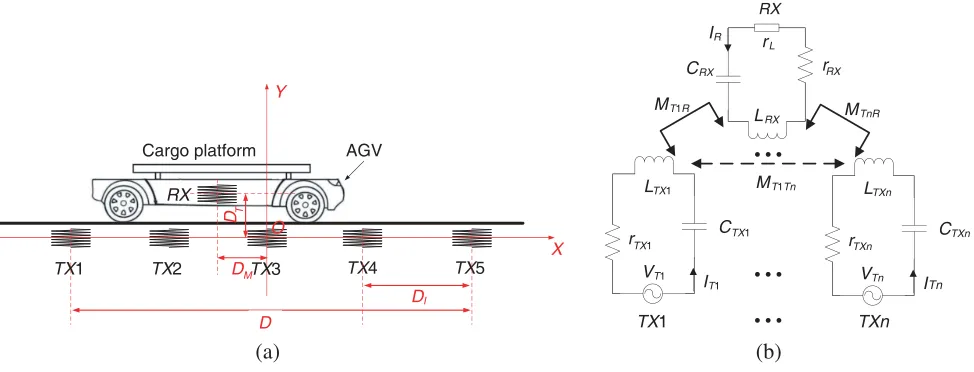
In this paper, the scenario of on-road AGV wireless charging application shown in Fig. 1(a) is investigated using circuit theory. The receiving coil mounted in a vehicle is marked as RX, and multiple feeding transmitters marked asT Xi (i= 1,· · ·, n) are arranged along a straight track where the AGV moves on. Fig. 1(b) illustrates the equivalent circuit model of the on-road WPT system of Fig. 1(a). This paper is organized as follows. The circuit model and optimal approaches of the proposed multiple-TX WPT system are presented in Section 2. In this section, the analysis and comparison of two cases of equal and optimal current (EC and OC Case) are illustrated to highlight the superiority of the current-optimized methodology. In Section 3, the results of the theoretical calculation are executed by MATLAB, and full-wave electromagnetic simulation is carried out by FEKO software to validate the theoretical calculation. Finally, Section 4 contains some concluding remarks.
DM
DT
O
TX1 TX2 TX3 TX4 TX5
RX X Y D DI CRX rL rRX LRX C
VT1
r LTX1
MTnR
MT1Tn
...
...
IR
IT1
RX
...
VTn Cr LTXn
ITn
MT1R
(a) (b)
Cargo platform AGV
TX1 TXn
TX1 TXn
TX1 TXn
Figure 1. (a) Multiple-TX WPT system for AGV charging. (b) Circuit topology of the proposed multiple-TX WPT system.
2. MODEL AND OPTIMIZATION OF MULTIPLE-TX WPT
According to Kirchhoff’s circuit laws, the electrical properties for the multi-TX WPT system in Fig. 1(b) can be described by the following formula:
⎡ ⎢ ⎢ ⎢ ⎢ ⎢ ⎣ 1 rRX ⎡ ⎢ ⎢ ⎢ ⎣
rTX1 jω0MT1T2 · · · jω0MT1Tn
jω0MT1T2 rTX2 · · · jω0MT2Tn
..
. ... ... . . .
jω0MT1Tn jω0MT2Tn · · · rT Xn
⎤ ⎥ ⎥ ⎥ ⎦
−jQT1R
−jQT2R
.. .
−jQTnR
−jQT1R −jQT2R · · · −jQTnR 1
⎤ ⎥ ⎥ ⎥ ⎥ ⎥ ⎦ ⎡ ⎢ ⎢ ⎢ ⎢ ⎣ IT1 IT2 .. . ITn IR ⎤ ⎥ ⎥ ⎥ ⎥ ⎦= 1 rRX
whereMTiTj (i, j = 1,· · · , n, i=j) is the mutual inductance betweenT Xi and T Xj;VT i,IT i, andrTXi
are the source voltage, loop current, and parasitic resistance of T Xi, respectively; IR and rRX are the loop current and total resistance of RX. rRX can be written as rRX = rRX +rL, where rRX and rL are the parasitic resistance of RX and the resistance of the load. QT iR = ω0MT iR/rRX is defined as
transmission quality factor, whereω0andMT iR are the resonance frequency and the mutual inductance
between T Xi and RX, respectively. It can be found that QT iR indicates the coupling strengths when RX and load are fixed.
The first n lines and the last line of Equation (1) can be written in Equations (2a) and (2b), respectively, as follows:
rTXiITi+jω0
n
j=1, j=i
(MT iT jITj)−rRX jQT iRIR=VTi (2a)
IR−j n
i=1
(QT iRITi) = 0 (2b)
The P DLfor the multi-TX WPT system,P DL=rL|IR|2, can be achieved via Eq. (2b)
P DL=rL n
i=1
QT iRITi
2
(3)
VTi can be expressed explicitly in terms ofITi using equations of Eqs. (2a) and (2b). The power gained from the i-th source, PT Xi, is calculated byPT Xi= Re(VTiI∗Ti).
PTXi =
rTXi+rRXQ2T iR|ITi|2+ω0QT iR
n
j=1, j=i
MT jRITjITi (4)
The detailed calculation of total feeding power to the WPT network, PT X =ni=1PTXi, is as follows:
PT X= n
i=1
rTXiI2Ti+rRX n
i=1
QT iRITi
2
(5)
For a traditional multiple-TX WPT system, equal current (EC Case) flows through each TX. The identical current,IT,I, can be derived from Equation (5)
IT,I =
√ PT X
n
i=1
rTXi+rRX n
i=1 QT iR
2 (6)
Combining Equations (3) and (6),P DL for a conventional multiple-TX system with identical currents in TXs is derived in Equation (7)
P DLI = PT XrL rRX+F1
1
(7)
whereF1 = (
n
i=1QT iR) 2
/ni=1rTXi
In order to maximizeP DLvia optimizingITi in each TX under the equality constraint of Eq. (5), we achieve optimized objective functions as follows.
max ITi P DL
(ITi) : rL n
i=1
QT iRITi
2
(8a)
s.t. n
i=1
rT XiI2Ti+rRX n
i=1
QT iRITi
2
The optimal solutions of ITi,OPT for Eq. (8) could be obtained by using the Lagrangian multiplier method. Introducing variable,λ, in a set of real numbers the optimization of Eq. (8) is constructed by Lagrange multiplier equation:
L(ITi, λ) =rL n
i=1
QT iRITi
2
+λ
⎡ ⎣n
i=1
rTXiI2Ti+rRX n
i=1
QT iRITi
2
−PT X
⎤
⎦ (9)
The necessary conditions of optimal solutions for Eq. (9) are ∇ITiL(ITi, λ) = 0 and ∇λL(IT i, λ) = 0, whose corresponding expansions are listed as follows:
ITi= QT iR(rL−r RXλ) λrTXi
⎛
⎝n
j=1
QT jRITj
⎞
⎠ (10a)
n
i=1
rT XiI2Ti+rRX n
i=1
QT iRITi
2
−PT X = 0 (10b)
From Eq. (10a), the relations of current flowing in different loops are deduced of ITi/ITj = (QTiR/rTXi)/(QTjR/rTXj), ∀i = j. Substituting the relations of ITi/ITj into Eq. (10b), the optimal
current (OC Case) in thei-th TX,ITi,OPT, is:
ITi,OPT=
√
PT XQTiR
⎛
⎝ n
j=1, j=i rTXj ⎞ ⎠ ⎡ ⎣n
s=1 Q2T sR
⎛
⎝ n
j=1, j=s rTXj ⎞ ⎠ ⎤ ⎦ ⎧ ⎨ ⎩ n j=1
rTXj+rRX ⎡ ⎣n
s=1 Q2T sR
⎛
⎝ n
j=1, j=s rTXj ⎞ ⎠ ⎤ ⎦ ⎫ ⎬ ⎭ (11)
By substitutingITi,OPTof Eq. (11) into Eq. (3), one can derive the optimalPDLof multi-TXs,PDLOP T.
PDLOP T = PT XrL rRX+F1
2
(12)
whereF2 =
n
i=1(Q2T iR/rTXi).
ComparingPDLI of EC Case in Equation (7) and the optimalPDLOP T of OC Case in Equation (12) for a multi-TX system, the only difference lies inF1 and F2. To order to compare the numeric value of
PDLI and PDLOP T, ΔF =F2−F1 is implemented as follows:
ΔF =
n
i=1, i=j
⎡
⎣(QT iRrTXj−QT jRrTXi)2
⎛
⎝ n
s=1, s=i,=j rTXs ⎞ ⎠ ⎤ ⎦ n i=1 rTXi n i=1 rTXi (13)
There are many groups of QT iRrTXj =QT jRrTXi for different sizes of the loop in a multi-TX system;
therefore, ΔF >0 is always tenable. Up to this point, the conclusion that the value ofPDLOP T of the proposed multi-TX system with current-controlled technique must be greater than that of PDLI of a conventional multi-TX system with the identical feeding current is true.
3. THEORETICAL CALCULATION AND FULL-WAVE ELECTROMAGNETIC SIMULATION VERIFICATION
dimension parameters of TX and RX are: the coil diameters of TX and RX are dT X =dRX = 0.31 m; the numbers of turns of TX and RX areTT X =TRX = 25; a 1.2-mm diameter copper wire with electrical conductivity of 5.7×10⁷S/m is used to wind the power transmission coils. The electrical parameters
of the WPT system calculated according to theory are: the self-inductance values of TX and RX are LT X = LRX = 40.55µH; the lumped capacitors of capacitance values of CT X = CRX = 625 pF are connected to TX and RX coils in series respectively to achieve the resonance frequency f0 = 1 MHz
(ω0= 6.28×10⁶rad/s); the parasitic resistance values of the TX and RX coils arerTXi =rRX = 1.96 Ω;
the load resistance isrL= 100 Ω. The relative positions of the TX and RX coils are shown in Fig. 1(a). The total charging interval between T X1 and T X5 is D = 2 m. The distances between two adjacent
TXs are identical and set asDI = 0.5 m, and the transmission distanceDT changes from 0.1 m to 0.7 m. The maximum output power of the whole system is PT X = 30 W, which is allocated by the five TXs according to distinct optimization goals.
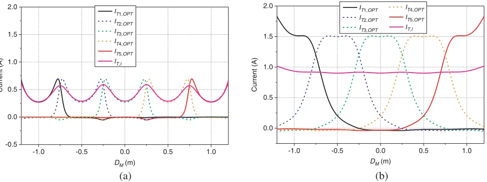
For 5-TX system, the transmission quality factorQT iRcan be obtained for different range shiftDM by calculating the MT iR and the known ω0 and rRX. The identical current, IT,I, in EC Case for the
traditional multiple-TX WPT system and the optimal current,ITi,OPT, in OC Case for maximizing the PDL system are calculated by MATLAB using the expressions in Equations (6) and (11), respectively. Figs. 2(a) and (b) show the current amplitude values of IT,I and ITi,OPT versus DM at two transfer distances of DT = 0.2 and 0.5 m, respectively. ITi,OPT is symmetrical about the position of T Xi. By comparing Figs. 2(a) and (b), it can be found that both ITi,OPT and IT,I increase along with the increase of DT. The reason is that the increasing current can maintain stable feeding power with increasing DT. Both of the fluctuation ranges of IT,I and ITi,OPT decrease with the increase ofDT.
-1.0 -0.5 0.0 0.5 1.0 -0.5
0.0 0.5 1.0 1.5 2.0
Current (A)
M IT1,OPT IT2,OPT IT3,OPT IT4,OPT IT5,OPT IT,l
-1.0 -0.5 0.0 0.5 1.0 0.0
0.5 1.0 1.5 2.0
Current (A)
IT1,OPT IT2,OPT IT3,OPT
IT4,OPT IT5,OPT I
(a) (b)
D (m) D M(m)
T,l
Figure 2. Calculated current values for EC and OC Cases in 5-TX AGV charging system, (a) DT = 0.2 m; (b)DT = 0.5 m.
In practice, the voltage source is more commonly used to feed power than the current source, and voltage source can only serve as the feeding source for wire port in FEKO, which is a comprehensive computational electromagnetics (CEM) software and is used as a means of verification in this paper. The feeding voltages of VTi and VTi,OPT for thePDLI andPDLOP T can be achieved by substituting IT,I andITi,OPT into Equation (2), respectively. The ith voltage feeding toT Xi is written as:
VTi = rT XiIT,I+rRX QT iR n
j=1
QT jRIT,I+jω0
n
j=1, j=i
MT iT jIT,I (14a)
VTi,OPT = rT XiITi,OPT+rRX QT iR n
j=1
QT jRITj,OPT+jω0
n
j=1, j=i
For the 5-TX system withDI = 0.5 m, MT iT j between T Xi and T Xj can be computed as
MT iT j|i=1,···,5
j=1,···,5
= ⎡ ⎢ ⎢ ⎢ ⎢ ⎣
MT1T1 MT1T2 MT1T3 MT1T4 MT1T5 MT2T1 MT2T2 MT2T3 MT2T4 MT2T5 MT3T1 MT3T2 MT3T3 MT3T4 MT3T5 MT4T1 MT4T2 MT4T3 MT4T4 MT4T5 MT5T1 MT5T2 MT5T3 MT5T4 MT5T5
⎤ ⎥ ⎥ ⎥ ⎥ ⎦
= ⎡ ⎢ ⎢ ⎢ ⎢ ⎣
0 3.6 0.38 0.11 0.04 3.6 0 3.6 0.38 0.11 0.38 3.6 0 3.6 0.38 0.11 0.38 3.6 0 3.6 0.04 0.11 0.38 3.6 0
⎤ ⎥ ⎥ ⎥ ⎥
⎦(µH) (15)
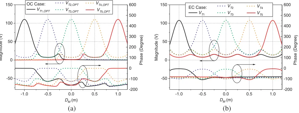
The feeding voltage values ofVTi andVTi,OPT are calculated using Equations (14) and (15). The magnitude and phase parts of the calculational results versus the position of RX, DM, are shown in Fig. 3. For both cases in the figure, the maximum feeding voltage magnitude of the i-th transmitter, T Xi, appears when RX moves to the position right above T Xi. By comparing the OC Case in Figure 3(a) and EC Case in 3(b), the main differences are the voltage phase values between corresponding T Xi. Fig. 4 shows the magnitude and phase parts versus the positions of TXs for OC and EC Cases when RX is placed at two locations of DM = 0 m and −0.25 m. The voltages feeding to the five TXs are symmetric about the position of RX for the two Cases. The voltage values shown in Figs. 3 and 4 are used in FEKO to verify the theoretical optimization results in the following pages.
-1.0 -0.5 0.0 0.5 1.0 -50
0 50 100 150
Magnitude (V)
VT2,OPT VT3,OPT
VT4,OPT
VT5,OPT
OC Case:
VT1,OPT
-200 -100 0 100 200 300 400 500 600
Phase (Degree
)
-1.0 -0.5 0.0 0.5 1.0 -50
0 50 100 150
Magnitude (V)
VT2 VT3
VT4 VT5
EC Case:
VT1
-200 -100 0 100 200 300 400 500 600
Phase (Degree
)
(a) (b)
M
D (m) D M(m)
Figure 3. Feeding voltage values versus DM in 5-TX wireless charging system when DT = 0.2 m. (a) The magnitude and phase parts for OC Case; (b) the magnitude and phase parts for EC Case.
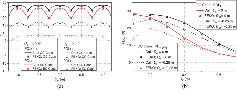
The calculatedPDLI andPDLOP T using the identical and optimal currents for 5-TX WPT system are illustrated in Fig. 5. The scatter contour lines of the counterparts shown in Fig. 5 are obtained by FEKO simulation to verify the presented theory. The feeding voltage values of voltage sources shown in Figs. 3 and 4 are used in FEKO simulation. PDLI andPDLOP T versusDM are shown in Fig. 5(a). It can be found thatPDLOP Ts in black lines are higher thanP DLIs in red lines over the whole research range from DM =−1.2 m to DM = 1.2 m. The differences between PDLOP Ts and P DLIs increase with the transmission distance of increasingDT. Therefore, the advantages of the proposed optimization method are more obvious when DT is long. When the position of RX is fixed at DM = 0 m and = −0.25 m, PDLs versus DT are shown in Fig. 5(b). PDLOP Ts of OC Case in black lines are always greater than
-1.0 -0.5 0.0 0.5 1.0 -100 -50 0 50 100 TX5 TX1 DM Magnitude (V)
Positon of TX M
VT,OPT; OC Case
VT; EC Case
-150 -100 -50 0 50 100 150 TX4 TX3 TX2 Phase (Degree )
-1.0 -0.5 0.0 0.5 1.0 -100 -50 0 50 100 TX5 TX1 DM Magnitude (V)
Positon of TX
VT,OPT; OC Case
VT; EC Case
-150 -100 -50 0 50 100 150 TX4 TX3 TX2 Phase (Degree ) (a) (b)
D = 0 m D M= -0.25 m
Figure 4. Feeding voltage values of OC and EC Cases versus the positions of TXs in 5-TX wireless charging system whenDT = 0.2 m, (a) DM = 0 m, (b)DM =−0.25 m.
-1.0 -0.5 0.0 0.5 1.0 -15 -10 -5 0 5 10 15 20 25 30 PDLOPT Cal.; OC Case FEKO; OC Case
PDLI
Cal.; EC Case FEKO; EC Case
PDL (W
)
PDLOPT Cal.; OC Case FEKO; OC Case
PDLI
Cal.; EC Case FEKO; EC Case
0.2 0.4 0.6
0 10 20 30
EC Case: PDLI
Cal.; D = 0 m FEKO; D = 0 m Cal.; D = -0.25 m FEKO; D = -0.25 m
OC Case: PDLOPT
Cal.; D = 0 m FEKO; D = 0 m Cal.; D = -0.25 m FEKO; D = -0.25 m
(a) (b)
PDL (W)
M
D (m) D T(m)
D T= 0.2 m D T= 0.5 m
M M M M M M M M
Figure 5. Simulated and calculated PDL of OC and EC Cases. (a) PDL values versus DM when DT = 0.2 m and 0.5 m, (b) PDL values versusDT whenDM = 0 m and−0.25 m.
when DM = −0.25 m. This is because the main power source is T X3 at DM = 0 m, and the coupling
coefficient between T X3 and RX decreases gradually with increase of DT. However, the main power
feeding to RX is from two transmitters of T X2 and T X3 at DM = −0.25 m case, and the coupling
coefficients between the two TXs (T X2 and T X3) and RX are increased and then decreased with the
increase of DT due to the offset placement of RX to T X2 and T X3. The simulated values shown in
scatter contour lines match pretty well with the calculated values shown in solid lines in Fig. 5, which verifies the theoretical scheme and optimization method proposed in Section 2.
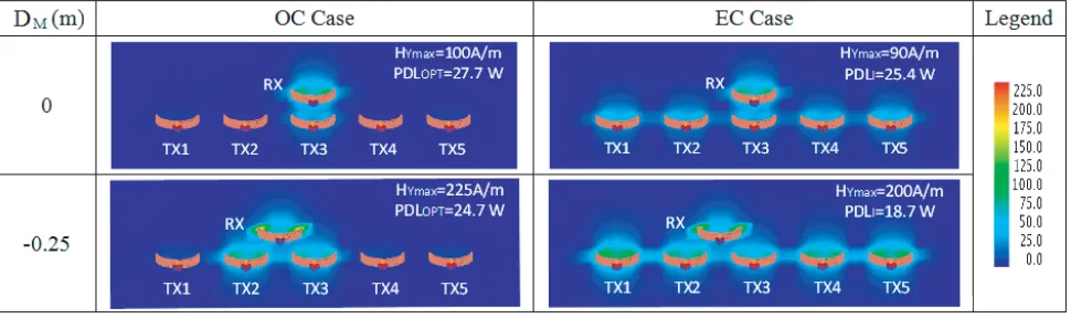
Based on Equations (14a) and (14b), the feeding voltage values of voltage sources for OC and EC Case are calculated for the five-TX wireless charging system. These voltage values are used in FEKO simulation to obtain the magnetic flux densities along the power transfer direction at DT = 0.2 m. Fig. 6 shows the simulation results in a setting plane which is perpendicular to the planes of coils. For DM = 0 m case,PDLOP T and maximum axial magnetic fieldHYmax of OC Case are higher than those
Figure 6. The distribution of magnetic fields of 5-TX wireless charging system whenDT = 0.2 m.
at DM = 0 m; however, PDLOP T = 24.7 W at DM = −0.25 m is lower than PDLOP T = 27.7 W at DM = 0 m. This is because each of the emission currents in T X2 and T X3 forDM =−0.25 m case is
larger than that in T X3 for DM = 0 m case (see Fig. 2(a)). The maximum magnetic flux density of DM =−0.25 m case exists aroundT X2andT X3; however, the power delivered to RX is still lower than
that ofDM = 0 m case. For EC Case, the similar conclusion thatHYmax (PDLOP T) at DM =−0.25 m
is higher (lower) than that at DM = 0 m is still valid. The same reason as OC Case can be used to clarify this similar conclusion.
4. CONCLUSIONS
In this paper, under the application background of on-road AGV wireless charging, the scheme of multiple-TX wireless charging is presented. The multiple TXs are lined along the AGV track to realize on-move recharging.
The multiple-TX WPT system is theoretically analyzed based on circuit theory. The optimal current solution of assigning currents at different TXs is proposed to maximize the PDL when the number of TXs is fixed. By contrast, the equal current case is presented to illustrate the advantages of the proposed optimal solution. The current parameters mapping to the corresponding voltage values of feeding sources are implemented. Based on the electromagnetic simulation software FEKO, the three-dimensional full-wave simulation is implemented using the transformation feeding voltage values to verify the optimization solution.
This paper provides a sound WPT recharging solution for a moving AGV using a multiple-TX system when the TXs are in linear arrangement.
ACKNOWLEDGMENT
This research was supported in part by the Natural Science Foundation of the Jiangsu Higher Education Institutions of China(Grant No. 19KJB510029), the open research fund of the National and Local Joint Engineering Laboratory of RF Integration and Micro-Assembly Technology (KFJJ20180203), the Joint Funds of the National Natural Science Foundation of China (U1636108), the Scientific Research Foundation for the High-Level Talents of Jinling Institute of Technology (jit-b-201719), and the Scientific Research Incubation Foundation of Jinling Institute of Technology (jit-fhxm-201802). Jin Zhang would like to thank Dr. Dong Chen for helpful discussions for improving this paper.
REFERENCES
2. Andr´e, K., K. Aristeidis, M. Robert, J. D. Joannopoulos, F. Peter, and S. Marin, “Wireless power transfer via strongly coupled magnetic resonances,” Science, Vol. 317, 83–86, 2007.
3. Sample, A. P., D. T. Meyer, and J. R. Smith, “Analysis, experimental results, and range adaptation of magnetically coupled resonators for wireless power transfer,” IEEE Transactions on Industrial Electronics, Vol. 58, 544–554, 2011.
4. Zhang, J. and C. Cheng, “Quantitative investigation into the use of resonant magneto-inductive links for efficient wireless power transfer,”IET Microwaves Antennas&Propagation, Vol. 10, 38–44, 2016.
5. Zhang, F., S. A. Hackworth, W. Fu, C. Li, Z. Mao, and M. Sun, “Relay effect of wireless power transfer using strongly coupled magnetic resonances,” IEEE Transactions on Magnetics, Vol. 47, 1478–1481, 2011.
6. Ahn, D. and S. Hong, “A study on magnetic field repeater in wireless power transfer,” IEEE Transactions on Industrial Electronics, Vol. 60, 360–371, 2013.
7. Zhong, W., C. K. Lee, and S. Y. R. Hui, “General analysis on the use of Tesla’s resonators in domino forms for wireless power transfer,” IEEE Transactions on Industrial Electronics, Vol. 60, 261–270, 2013.
8. Zhang, J. and C. Cheng, “Analysis and optimization of three-resonator wireless power transfer system for predetermined-goals wireless power transmission,”Energies, Vol. 9, 274, 2016.
9. Fu, M., Z. Tong, C. Ma, and X. Zhu, “Efficiency and optimal loads analysis for multiple-receiver wireless power transfer systems,”IEEE Transactions on Microwave Theory &Techniques, Vol. 63, 801–812, 2015.
10. Fu, M., H. Yin, M. Liu, Y. Wang, and C. Ma, “A 6.78 MHz multiple-receiver wireless power transfer system with constant output voltage and optimum efficiency,” IEEE Transactions on Power Electronics, Vol. 33, 5330–5340, 2018.
11. Hao, P., L. Lu, and Z. Liang, “Priority evaluation for multiple receivers in wireless power transfer based on magnetic resonance,” 2016 IEEE Wireless Power Transfer Conference (WPTC), 1–4, 2016.
12. Zhang, J. and F. Wang, “Efficiency analysis of multiple-transmitter wireless power transfer systems,”International Journal of Antennas and Propagation, Vol. 2018, 11, 2018.
13. Zhang, C., D. Lin, and S. Y. Hui, “Basic control principles of omnidirectional wireless power transfer,”IEEE Transactions on Power Electronics, Vol. 31, 5215–5227, 2016.
14. Johari, R., J. V. Krogmeier, and D. J. Love, “Analysis and practical considerations in implementing multiple transmitters for wireless power transfer via coupled magnetic resonance,”
IEEE Transactions on Industrial Electronics, Vol. 61, 1774–1783, 2013.
15. Kiani, M. and M. Ghovanloo, “The circuit theory behind coupled-mode magnetic resonance-based wireless power transmission,” IEEE Transactions on Circuits and Systems I: Regular Papers, Vol. 59, 2065–2074, 2012.
16. Jadidian, J. and D. Katabi, “Magnetic MIMO: How to charge your phone in your pocket,”
International Conference on Mobile Computing and Networking, 495–506, 2014.
17. Moghadam, M. R. V. and R. Zhang, “Node placement and distributed magnetic beamforming optimization for wireless power transfer,”IEEE Transactions on Signal and Information Processing over Networks, Vol. 4, 264–279, 2018.
18. Yang, G., M. R. V. Moghadam, and R. Zhang, “Magnetic beamforming for wireless power transfer,”
2016 IEEE International Conference on Acoustics, Speech and Signal Processing (ICASSP), 3936– 3940, 2016.
19. Lee, J. and S. Nam, “Fundamental aspects of near-field coupling small antennas for wireless power transfer,”IEEE Transactions on Antennas and Propagation, Vol. 58, 3442–3449, 2010.
21. Chen, Z., H. Sun, and W. Geyi, “Maximum wireless power transfer to the implantable device in the radiative near field,” IEEE Antennas and Wireless Propagation Letters, Vol. 16, 1780–1783, 2017.
22. Daniel, K., C. Rathge, and U. Jumar, “Design methodology for high efficient inductive power transfer systems with high coil positioning flexibility,”IEEE Transactions on Industrial Electronics, Vol. 60, 372–381, 2013.
23. Lu, S., C. Xu, R.-Y. Zhong, and L. Wang, “A RFID-enabled positioning system in automated guided vehicle for smart factories,” Journal of Manufacturing Systems, Vol. 44, 179–190, 2017. 24. Huang, S.-J., T.-S. Lee, W.-H. Li, and R.-Y. Chen, “Modular on-road AGV wireless charging