Perceptually-Adaptive Collision Detection
for Real-time Computer Animation
Carol O'Sullivan
A thesis submitted for the degree of Doctor of Philosophy in Computer Science
University of Dublin, Trinity College Department of Computer Science
Declaration
I declare that the work described in this thesis has not been submitted for a degree at any other university, and that the work is entirely my own.
Signature
__________________
Permission to lend and/or copy
I agree that the library in Trinity College may lend or copy this thesis upon request.
Signature
__________________
Acknowledgements
Thanks to my supervisor Dr. Steven Collins for his advice and guidance, and for his prompt reading of the final manuscript. Many thanks also to Dr. Ralph Radach from the Institute of Psychology in the Technical University of Aachen for all his help with respect to the psychophysical aspects of this work.
I am also grateful for the support of Professor John Byrne, Head of the Computer Science department in Trinity College Dublin and of Dr. Michael Sherwood-Smith in the Department of Computer Science in University College Dublin. Thanks also to Dr. Ronan Reilly from University College Dublin for helping to formulate some of the ideas of this thesis, to Dr. Shane O'Mara from the department of psychology in Trinity College Dublin, and to my post-graduate student John Dingliana for his co-operation. This work has been funded in part by a basic research grant from Enterprise Ireland.
Abstract
Perceptually-Adaptive Collision Detection for Real-time Computer Animation Carol O'Sullivan
Supervisor: Dr. Steven Collins
The aim of interactive animation systems is to create an exciting and real experience for viewers, to give them a feeling of immersion, of “being there". The tendency in the past has been to attempt to achieve this by matching as closely as possible the physics of the real world, with varying degrees of success. However, it is the human visual system that receives and interprets the visual cues from the surrounding environment, and it ultimately determines what we perceive. Therefore, we must look beyond the laws of physics to find the secret of reproducing visual reality.
In interactive animation applications such as VR or games, it cannot be predicted in advance how a user or the entities in a virtual world will behave, so the animation must be created in real-time. There are many bottlenecks in such systems, collision detection being a major one. A trade-off between detection accuracy and speed is necessary to achieve a high and constant frame-rate. However, it is possible to reduce perceived inaccuracy by taking perceptual factors into account, and also by estimating where on the screen a viewer is looking, possibly using an eye-tracking device, or by attaching more importance to certain objects in a scene, or to regions of the screen.
In this thesis we present the first perceptually-adaptive collision detection algorithm. New collision scheduling strategies are also presented and evaluated, along with a new interruptible algorithm to test for the intersection between two sphere trees. A model of human visual perception of collisions is developed, based on
two-dimensional measures of eccentricity and separation. The model is validated by
Contents
1 INTRODUCTION... 1-1
1.1 INTRODUCTION... 1-1 1.1.1 Collision detection... 1-2 1.1.2 Visual Perception ... 1-4 1.2 OBJECTIVES AND SCOPE... 1-6 1.3 ORGANISATION OF THE THESIS... 1-7 1.4 CONTRIBUTIONS OF THE THESIS... 1-8
2 PREVIOUS WORK... 2-1
2.1 APPLICATIONS OF COLLISION DETECTION: PAST, PRESENT AND FUTURE. ... 2-1 2.2 HYBRID COLLISION DETECTION... 2-3 2.2.1 Narrow Phase: The Exact Level... 2-4 2.2.2 Narrow Phase: Progressive Refinement Levels ... 2-7 2.2.3 Broad Phase Collision Detection ... 2-9 2.3 ADAPTIVE REFINEMENT... 2-11 2.4 OTHER POSSIBILITIES... 2-11
3 VISUAL PERCEPTION... 3-1
3.1 INTRODUCTION... 3-1 3.2 VISUAL PERCEPTION IN COMPUTER SYSTEMS... 3-3
4 THE APPLICATION ... 4-1
4.1 OVERALL DESIGN OF APPLICATION... 4-1
4.2 COLLISION DETECTION... 4-4 4.2.1 Broad Phase... 4-5 4.2.2 Narrow Phase ... 4-6 4.3 ADDING INTERRUPTION... 4-10 4.4 MEASURING INACCURACY AND PRIORITISING COLLISIONS... 4-12 4.4.1 Overall inaccuracy: ∆... 4-12 4.4.2 Perceptually-weighted Inaccuracy: P... 4-16 4.4.3 Collision Priority... 4-25 4.5 SCHEDULING... 4-25
5 ANALYSIS AND PERFORMANCE... 5-1
5.1 INTRODUCTION... 5-1 5.2 INTERRUPTIBLE VS. NON-INTERRUPTIBLE COLLISION DETECTION... 5-3 5.2.1 No Interruption ... 5-3 5.2.2 Interrupting at 0 ... 5-8 5.2.3 Interrupting at X... 5-12 5.2.4 Discussion... 5-13 5.3 PERCEPTUAL INTERRUPTIBLE COLLISION DETECTION VS. NON-PERCEPTUAL INTERRUPTIBLE
COLLISION DETECTION... 5-18 5.3.1 Perceptually Sorted Sequential Scheduling ... 5-18 5.3.2 Priority Queue Scheduling... 5-21
6 PSYCHOPHYSICAL EXPERIMENTS... 6-1
6.3.4 Location ... 6-28 6.3.5 Direction of Offset and Direction of Motion ... 6-30 6.3.6 Distractors ... 6-31 6.4 VALIDATION AND DISCUSSION... 6-35
7 CONCLUSIONS AND FUTURE WORK ... 7-1
List of Figures
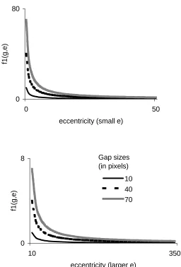
Figure 1.1: The wildebeest stampede from "The Lion King". Disney... 1-1 Figure 1.2: A highly accurate but intrusive eye-tracker ... 1-5 Figure 1.3: The low-cost, non-intrusive eye-tracker from Vision Control Systems ... 1-6 Figure 2.1: A convex and a non-convex polygon ... 2-5 Figure 3.1: The Müller-Lyer illusion... 3-1 Figure 3.2: The layers of the eye... 3-6 Figure 3.3: the fibrous layer of the eye ... 3-7 Figure 3.4: the vascular layer of the eye ... 3-7 Figure 3.6: Calculation of Visual angle. ... 3-10 Figure 3.7: The Visual Pathways ... 3-11 Figure 3.8: Typical Retinal Neuron ... 3-12 Figure 3.9: Different types of collision events ... 3-18 Figure 3.10: Interpenetrating entities of different colours ... 3-19 Figure 3.11: Different stimulus orientations (a)(b), and displacement direction (c)... 3-23 Figure. 4.1: Sample Entities ... 4-3 Figure 4.2: An entity and 4 levels of its sphere-tree... 4-8 Figure 4.3: Design of a sphere-tree ... 4-8 Figure 4.4: A 2D depiction of a scene with erroneous collisions... 4-13 Figure 4.5: Three possibilities for collisions detected at lowest level of accuracy ... 4-15 Figure 4.6: Three possibilities for potential collisions allowed to proceed to a higher level of accuracy4-15 Figure 4.7: The location of the Centre of Collision, C ... 4-19 Figure 4.8: Calculation of the Centre of Collision, C ... 4-19 Figure 4.9: two frames, identical except for the fixation point. ... 4-20 Figure 4.10: Perceptual function f1. ... 4-23
Figure 4.11: Perceptual function f2 for different values of C... 4-24
Figure 4.12: Perceptual function f3... 4-24
1
Introduction
1.1 Introduction
[image:11.595.120.476.409.662.2]The demand for highly interactive computer systems is increasing rapidly, as people wish to communicate with computers in a more natural fashion. This need for interaction adds to the pressure on developers of systems to produce realistic, real-time animations. However, this high degree of interaction with the user may also be exploited, in order to adaptively improve the realism of real-time animations. In order to maintain a user’s immersion in the animation, a high and constant frame rate is necessary. Realistic rendering, motion synthesis, and collision handling all place an impossibly high computational load on graphics workstations. In a scene with many moving objects, maintaining the target frame rate, while rendering each frame to the highest level of image realism and controlling motion and interaction of objects to full accuracy, is virtually impossible with single-processor work-stations.
Many interactive animation systems, such as games or simulations, require large numbers of virtual entities which are moving and interacting with each other, and/or with one or more users. In these applications, we cannot predict in advance how the user or the entities will behave, so we must create the animation as we watch it, i.e. in real-time. This means that the image must be re-drawn at least 10 times per second, although for true real-time performance the generation of up to 60 frames per second (f.p.s) may be required. Hence, there will be 100 milliseconds available, at the most, to update all entities in the simulation, and then render the new scene. There are many bottlenecks in such systems. Depending on the level of realism required, rendering and motion synthesis algorithms require a large amount of processing power. In multi-user systems, network lag is a major issue.
Some solutions to these problems could be to increase the computational power, add hardware accelerators, and develop parallel algorithms that may be implemented on multiple processors. However, using such approaches, the problem is postponed rather than eliminated, and such computational power will not be available to a wide range of users. An additional challenge is maintaining a constant frame rate. The time taken to render a given scene is dependent on the current level of complexity. Some frames may require only one object to be rendered, whereas a sudden change of view may cause many more interacting objects to be visible in subsequent frames. Obviously, the latter set of frames will take longer to process than the former, regardless of the computational power available. Hence, increasing computational power alone is not the solution. It may sometimes be necessary to trade realism and accuracy for speed, and aim to achieve optimal realism in the time available, thus maintaining a high and constant frame-rate.
1.1.1
Collision detectionA Collision Handling system is necessary to enforce solidness, and ensure that entities behave as expected when they come into contact, i.e. they should not interpenetrate, and their behaviour subsequent to collision should be compatible with their physical properties. This involves two very distinct phases: Collision Detection, and Collision Response. Detection is a problem of kinematics, while response is a problem of dynamics.
A possible application of real-time collision handling could be a game where a user must navigate his/her way through a rockfall without being hit. As multiple rocks are falling, they hit off each other and the edges of a ravine, either bouncing or breaking into smaller rocks. In order to achieve this effect, collisions between the rocks and with the ravine edges must be detected. Many other application areas exist: Large-scale Virtual Reality (VR) systems with thousands of moving entities; Crowd simulations; Educational simulations with chemical molecules or blood cells. An example could be the wildebeest stampede scene from the Disney film "The Lion King" (see Figure 1.1), where behavioural rules were used to simulate the behaviour of many objects, similar to the approach taken for flocking of birds ( or Boids) in [Reynolds 1987]. The stampede scene was generated off-line using many hours of computer time. To achieve anything approaching such an effect in real-time, efficient collision handling algorithms are necessary.
In some applications, such as scientific simulation, fully accurate physically-based collision handling is necessary. In these cases, solutions must be considered such as degrading the image realism to maintain physically-based response, or increasing the number of processors and developing parallel algorithms for tasks such as rendering and collision detection. However, in a growing number of applications, what is important is that viewers perceive events, such as collision response, to be accurate. Testing all potentially colliding objects at full resolution is not always necessary to achieve this goal. In fact, in some cases this testing may be fully redundant, for example, if the viewer is not actually looking at the objects when they collide.
1.1.2
Visual PerceptionWhat effects do properties such as size, velocity, colour, and semantics have on our perception of objects and their interactions? Could a combination of weights be given to these effects, in order to prioritise and schedule collision processing? What if it was known where exactly in the visible scene the viewer was looking? We shall see later in this thesis that it is a well-established fact that visual and spatial acuity falls off rapidly with increasing eccentricity of stimuli from the point of the eye's fixation. Is this also true for collisions? Would a viewer be less likely to notice a repulsion or interpenetration if it happened on a part of the screen at which they were not directly looking, or how close to the point of fixation, and how significant must the anomaly be for it to be noticed? These considerations begin to reveal the complexity of the problem, and lead to the following two conclusions:
- A study of human visual perception could yield important information about how
viewers perceive collisions, and hence enable a prioritisation of potential collisions to process within a given frame of an animation.
- Estimating the position on-screen where a viewer is looking could be very useful for
Traditionally, the use of eye-trackers has been confined to medical and scientific research. These types of trackers are very accurate, but also very invasive, involving the use of head restraints, bite bars, and even scleral coils which are inserted into the eye in a contact lens. This technology is too intrusive and immobile for use in an interactive graphical system (see Figure 1.2). In order to convince the computer graphics community that this form of technology is feasible, the eye-tracking technology must be much more usable. There are, however, some mobile, non-intrusive, and low-cost trackers being developed, and we have experimented with one such model from Vision
Control Systems (see Figure 1.3). Of course, the drawback at present with such
[image:15.595.77.515.377.632.2]systems is a loss of accuracy, both spatial and temporal, and we found that this eye-tracker was infeasible for use in this research for these reasons. However, once the use of such trackers in areas other than medical and scientific becomes established, the technology will improve dramatically.
Figure 1.2: A highly accurate but intrusive eye-tracker 1
1
Images downloaded from http://hering.berkeley.edu/zbackups/facphotos/SRI.html. The eye-tracker used is
the SRI Dual-Purkinje Eye-Tracker, which measures eye position according to the reflections of infrared
Figure 1.3: The low-cost, non-intrusive eye-tracker from Vision Control Systems
1.2 Objectives and Scope
In this thesis, we address the problem of real-time collision detection between large numbers of visually homogeneous (i.e. similar) objects. The following options are available at present:
- Perform fully accurate collision detection: This ensures the realism of collision
handling if enough time is available, but causes frame-rate problems for increasing numbers of objects
- Degrade of detection accuracy for speed: This option may deliver a high and
constant frame rate, but the degradation of accuracy can have un-predictable results, and the animation may look very unrealistic.
1.3 Organisation of the thesis
Chapter 2, Previous Work: This chapter reviews the current state of the art in collision detection, and justifies further research in this area.
Chapter 3, Visual Perception: This chapter starts by reviewing the precedents for perceptually-driven techniques in the wider field of computer graphics. To provide an understanding for later discussion, the basics of visual perception are explained from various perspectives. Finally, a detailed discussion of the factors which affect the perception of collisions is provided.
Chapter 4, The Application: A real-time animation system was developed to test the ideas presented in this thesis. The design of this system is explained in this chapter, as are the collision detection algorithms developed. Our new scheduling strategies are also presented, along with new metrics which can be used to measure total and perceived collision inaccuracy. Models of human visual perception of collisions are developed.
Chapter 5, Analysis and Performance: A comprehensive suite of tests were carried out to test the performance of our collision detection algorithms, both in terms of efficiency and perception, under a range of conditions. The perceptual models described in the previous chapter were used to schedule collisions, and the metrics were used to measure the inaccuracy introduced by our new algorithms. The results of these tests are presented here.
Chapter 6, Psychophysical Experiments: In this chapter we describe the psychophysical experiments that were conducted on human subjects to determine the validity of the model of collision perception developed in Chapter 4, and used to schedule collisions in Chapter 5.
1.4 Contributions of the Thesis
- We present the first perceptually-adaptive collision detection algorithm.
- Our approach has been validated through psychophysical experiments, which
investigate the sensitivity of humans to degradations in collision accuracy. To our knowledge, no such psychophysical experiments have ever been conducted before.
- New collision scheduling strategies are also presented and evaluated. Again, we are unaware of any other research which implements and compares different methods of ordering collision processing.
- A new interruptible algorithm to test for the intersection between two sphere trees has been developed, which integrates the best properties of two existing algorithms
- We have also contributed to the fields of Human Computer Interaction, and
eye-movement research, by proposing a potential new application of eye-tracking
2
Previous Work
In this thesis, we are proposing the hypothesis that adaptive techniques, coupled with a model of visual perception of collisions, may be used to enhance the realism of collision handling in real-time applications of many homogeneous objects. We also maintain that this approach may be extended to other areas where the processing of fine detail leads to a computational bottleneck. Before we present and validate our solutions, we must first examine the current state of the art in collision detection. This chapter first discusses the applications of collision detection in Section 2.1. In Section 2.2 the methods currently used for the various phases of collision detection algorithms are presented. In Section 2.3, the application of adaptive refinement to this problem is examined, and alternative solutions are considered in Section 2.4.
2.1 Applications of Collision Detection: Past, Present and Future.
The original motivation for Collision Detection algorithms arose in areas such as CAD and Robotics, where the desire was to do more work on the computer, and to off-load work from the human designer or planner. Problems such as handling many different CAD shape descriptions, VLSI layout, robot path planning, bin packing, and assembly planning gave rise to off-line algorithms, where objects positions and motions were fully predictable over time, and “what if” analysis was done to generate an optimum solution. Real-time performance was not an issue in such systems, and fully accurate mathematical intersection tests could be utilized.
Robotics applications in the past were typically characterized by static scenes, where one or more robotic devices performed pre-specified tasks. Therefore, pre-processing could be used to predict where collisions would happen. However, with the development of more autonomous robots, who can operate in unknown environments, and whose behaviour is impossible to predict in advance, this situation has also changed. The goal in robotics is no longer just efficient path planning, but to support a real-time safety system that warns of imminent collisions, such as proposed by [Shaffer and Herb 1992].
Most of the robotics research has also been into the more complex Collision Avoidance
problem. However, as most collision avoidance systems incorporate collision detection by necessity, this research is also very relevant in the field of computer graphics, and much cross-over research has occurred between the fields. For example, the collision detection algorithm proposed in [Lin and Canny 1991] and [Lin 1993] has been used extensively in both robotics and animation.
The range of applications which require collision detection is extensive. Vehicle simulators are one case in point, where the users manipulate a steering device, and attempt to avoid obstacles in their way. In molecular modeling, simulations allow interactive testing of new drugs to examine how molecules interact and collide with each other. Training and education systems that realistically model the movement of objects within the geometric constraints of their layout, allow designers to experiment interactively with different strategies, e.g. to assemble or disassemble equipment, to perform a virtual surgery, or to test different paths that a robot could take. Such simulations are a safe and cheap way to teach.
Virtual Reality (VR) applications allow users to enter a computer-generated virtual world and interact with graphical objects and virtual agents with a sense of reality. Such systems may be either immersive, or desktop based. One thing they have in common is a requirement for extremely high and constant frame-rates. Physical interactions such as touching, hitting and throwing are usually triggered by collision. The more objects in the environment, and the more complex these objects are, the higher the burden on the engine which powers the animation, and hence the greater the need for extremely rapid collision detection. Increasing performance of V.R. is often driven by hardware developments, as in [Rohlf and Helman 1994], but significant opportunities exist to increase performance via algorithmic improvement.
We have seen that there is a requirement for collision detection in almost all systems that animate graphical objects, or which need to determine potential collisions with real objects in advance. This poses a significant challenge in the area of real-time systems, and as the demand for more realism and interaction in such systems is constantly increasing, it is also likely to remain a challenge for quite some time into the future.
2.2 Hybrid Collision Detection
When animating more than two objects, the most obvious problem which arises is the
O(N2) problem of detecting collisions between all N objects. This is known as the
all-pairs problem. It is obvious that this is an undesirable property of any collision detection algorithm, and several techniques have been proposed to deal with it. Hybrid collision detection, a term coined by [Kitamura et al. 1994], refers to any collision detection method which first performs one or more iterations of approximate tests to identify interfering objects in the entire workspace and then performs a more accurate test to identify the object parts causing interference. [Hubbard 1995] and [Cohen 1995] also propose hybrid algorithms for collision detection. The former refers to the two levels of
the algorithm as the broad phase, where approximate intersections are detected, and
the narrow phase, where exact collision detection is performed. Such an approach is essential for acceptable collision detection performance. The narrow phase itself may also consist of several levels of intersection testing between two objects at increasing levels of accuracy, the last of which may be fully accurate. We shall refer to these as the
2.2.1
Narrow Phase: The Exact LevelAny collision detection algorithm depends on the technique used to model the objects, and the data structure used to represent that model. The narrow phase, where exact collision detection is performed, depends greatly on the object representation scheme used.
Polygonal representations of surfaces are widely used to represent surfaces in 3D
graphics. Surfaces, which are intrinsically planar, such as those on building exteriors and cabinets, can be easily and naturally represented in this way. However, virtually any surface can be represented by polygons if the number of polygons is sufficiently high. This leads, however, to an approximate representation only. In order to reduce the faceted effect of these surfaces, the number of polygons has to be increased to such an extent that affects space requirements and computation time of algorithms processing the surface. Many different special cases must be handled, and cases may occur where polygon edges “tunnel” through each other, or smaller surfaces pass through an entire polygon. A major advantage to using polygonal representations of objects is the fact that many manufacturers provide specialized acceleration hardware to implement common operations on polygons, such as clipping and shading.
Polyhedral methods are not well suited to surfaces that deform in time, and which roll or
slide against each other. In such cases High-level surface representations are more
desirable. One such representation is a collection of Parametric Patches, which are
regions on a curved surface bounded by parametric curves. The number of parametric patches needed to approximate a curved surface to a reasonable degree of accuracy is many fewer than the number of polygonal patches that would approximate it to the same
level. Implicit Surfaces are defined using implicit functions, and also have some
The drawback of these higher-level solutions is that the algorithms for processing them are usually more complex, and hence slower. This is another important reason that polygonal representations are prevalent. They are most useful for modelling objects which are deformable, such as cloth garments and blobby, jelly-like substances which decompose and split over time. We do not address the problem of collisions between such objects in this thesis. We are concerned with collisions between rigid objects, which retain their shape over time. Such objects are usually modelled using the polygonal representations mentioned above, and hence there has been much activity in the development of efficient collision detection algorithms between these models.
Polygonal models can be either convex, or non-convex. If a polygon is convex, that means that the line between any two points inside the polygon must also lie completely inside (see figure 2.1). The concept extends to three dimensions, where a surface composed of polygons is called a polytope. If the polytope is convex, then any line between two points inside this area must lie completely within the surface defined by such a polytope. Most of the work on collision detection techniques has concentrated on detecting collisions between convex polytopes. Such approaches fall into two broad
categories: Feature-based methods, and Simplex-based methods.
Figure 2.1: A convex and a non-convex polygon
Feature-based methods concentrate on the inter-relations between the vertices, edges and faces of two polytopes, i.e. their features. The main goal of such algorithms is to detect whether two polytopes are touching or not. The most significant of these
algorithms is the Lin-Canny algorithm mentioned in Section 2.1 [Lin and Canny 1991]
[Lin 1993] which has been regarded until recently as the fastest solution to such problems.
Convex
The Lin-Canny algorithm determines whether two objects are disjoint or not, by computing the distance between their closest features. It tracks these features, and caches them between subsequent calls to the algorithm. In this way it exploits coherence, because the closest features will not change significantly between successive frames, and “feature-stepping” is used to keep the closest features up to date, i.e. if the closest features have changed, they are going to be adjacent to the those cached, and hence finding them is quite efficient. The algorithm to track these features runs in expected constant time if the collision detection time-step (i.e. the steps which the animation takes before each iteration of the collision detection algorithm) is small relative to the speed at which the objects are moving. The algorithm has been built into a general collision detection package I-Collide, described in [Cohen et al. 1995] and [Ponamgi et al. 1997] which is freely available on the World Wide Web. This has contributed to the popularity of their algorithm.
The Lin-Canny algorithm does not handle penetrating polytopes, however, and if such a condition arises the algorithm enters an infinite loop. A quick-fix to this problem is to force termination after a maximum iteration, and return a simple result stating that the objects have collided. However, this solution is quite slow, and no measure of penetration is provided. This is a significant weakness, because the condition of inter-penetrating objects will occur very frequently unless the objects are moving quite slowly, and/or if the detection time-step is quite small. This is unrepresentative of most situations in which real-time collision detection is necessary. If inter-penetration occurs, and more information is needed about the exact time of contact, back-tracking is necessary to pin-point the exact instant in time when collision occurred. This is a slow and cumbersome process. The code is also very complex, with many special cases being handled separately (e.g. parallel features), and it is difficult to configure, with several numerical tolerances which need to be adjusted to achieve the desired performance.
Simplex-based algorithms have provided improvements on the Lin-Canny algorithm. A simplex is the generalisation of a triangle to arbitrary dimensions. The approach in these cases is to treat a polytope as the convex hull of a point set. Operations are then performed on simplices defined by subsets of these points. The first of such algorithms
was presented in [Gilbert et al. 1988] and is commonly referred to as GJK. The main
strength of this algorithm is that, in addition to detecting whether two objects have collided or not, it can also return a measure of interpenetration. [Rabbitz 1994] improved upon GJK by exploiting coherence, and [Cameron 1997] developed it further to produce
the algorithm which is known as Enhanced GJK. This algorithm achieves the same
almost-constant time complexity as Lin-Canny, while eliminating most of its main weaknesses. Mirtich claims that the V-Clip algorithm requires fewer floating-point operations than Enhanced GJK, and is hence more efficient, but it is also admitted that the GJK algorithms return the best measures of penetration.
The proponents of the above algorithms usually claim that extending their work to cater for non-convex polytopes is easily accomplished. Non-convex polytopes can be represented by hierarchies of convex components. A “pass the parcel” approach is recommended, with collision checking being performed between the convex hulls of successive subsets of convex components, which are then unwrapped when a collision is detected. Results are rarely presented for such operations, and the focus of the validation performed is mainly on the efficiency of the intersection tests between two convex objects. Mirtich admits that although this technique works well for slightly non-convex objects, it becomes very inefficient as the level of non-non-convexity increases. Therefore, these techniques are very useful for situations where a small number of convex, or slightly non-convex objects are interacting in real-time, but in other situations techniques based on hierarchical representations are much more suitable.
2.2.2
Narrow Phase: Progressive Refinement LevelsTrees of bounding volumes are used, each level approximating the object. This is a form of Level Of Detail (LOD) representation of the object. This differs from the polygonal levels of detail used in multiresolution methods for faster rendering of complex objects, or surfaces such as mountainous terrain [Hoppe 1996, 1997, 1998][Rossignac and Borrel 1993]. In such techniques, the aim is to render an approximation which is as visually similar to the original model as possible. LODs for collision detection are always conservative approximations to the object, and the choice of volume is usually based on the speed of their intersection tests. More recently emphasis has been placed on their ability to approximate the geometry of the bounded object. The following hierarchies have been used:
− AABB-trees [Von Den Bergen 1997]. Axis Aligned Bounding Boxes are used, the advantage of these being their ease of computation and overlap testing.
− Octrees [Sammet and Webber 1988][Kitamura et al. 1994] Octrees are built by recursively sub-dividing the volume containing an object into eight octants, and retaining only those octants which contain some part of the original object as nodes in the tree. Such a data structure is simple to produce automatically, and lends itself to efficient and elegant recursive algorithms. The disadvantage of this approach is that each level of the hierarchy does not fit the underlying object very tightly.
− Sphere Trees [Hubbard 1996][Palmer and Grimsdale 1995][Quinlan 1994]. The main advantages of using spheres are that they are rotationally invariant, making them very fast to update, and it is very simple to test for distances between them, and test for overlaps. The disadvantage is that spheres do not approximate certain types of objects very efficiently. Hubbard attempts to improve upon this by building first a medial axis surface, which is like a skeleton representation of an object, and then placing the spheres upon this to provide a tighter-fitting approximation to the object. [O’Rourke and Badler 1979] also developed a method of tightly fitting spheres to an object.
− OBB-trees [Gottshalk et al. 1996]. These hierarchies consist of tightly-fitting Oriented Bounding Boxes. It is claimed that using an algorithm based on a separating axis, it can accurately detect all the contacts between large complex geometries at interactive rates. However, it is admitted that other methods are very good at performing fast rejection tests, and a disadvantage of OBB-trees over Sphere trees is that they are slower to update. A similar approach is taken in
[Klosowski et al. 1997], who use hierarchies of k-DOPs, or discrete orientation
polytopes, which are convex polytopes whose facets are determined by half spaces whose outward normals come from a small fixed set of k orientations. Again, they implement it with a small number of highly complex objects, for the purposes of haptic force-feedback. If there are a large number of objects between which fast rejection or acceptance is needed, the update time needed for these approximations is likely to add an unacceptable additional burden.
− ShellTrees [Krishnan et al 1998, a, b]. These trees consist of oriented bounding boxes and spherical shells, which enclose curved surfaces such as Bezier patches and NURBS. They are particularly suited to collision detection between the higher-order surface representations discussed in the previous section.
2.2.3
Broad Phase Collision Detection[Hubbard 1995] highlights three potential weaknesses of collision detection algorithms.
The most serious of these is the all-pairs weakness discussed above, where every
object in the scene must be compared with every other one at every collision timestep of the animation. Most research has concentrated on alleviating this problem. A second
problem is what he calls the fixed-timestep weakness. Allowing the objects to move
larger distances before checking whether they intersect leads to a more efficient algorithm, but it is possible that some collisions will be missed, and objects will tunnel through each other. Decreasing the size of the time-step would reduce the chances of this happening, but would cause a lot of extra unnecessary intersection tests. The third
weakness refers to the narrow phase, and is the pair-processing weakness. This
Hubbard recommends the use of an adaptive timestep, which becomes small when collisions are likely, and large when they are not. For the broad phase of his algorithm, 4-dimensional structures called space-time bounds are used, which provide a conservative estimate of where an object may be in the future. The fourth dimension represents time. Overlaps of these bounds trigger the narrow phase, which is based on hierarchies of spheres. Collision detection between sphere trees is robust, thus solving the pair-processing problem. Using the space-time bounds, attention is focused on the objects which are likely to collide, and those far away can be ignored, thus alleviating both the all-pairs weakness and the fixed-timestep weakness. [Cameron 1990] also addresses the fixed-timestep weakness through the use of four-dimensional bounding structures.
In [Cohen et al. 1995] multiple object pairs are “pruned” using bounding boxes. Overlapping bounding boxes then trigger the narrow phase of the algorithm. Their “Sweep and Prune” algorithm orthogonally projects axis-aligned bounding boxes of all objects onto the x, y and z-axes. This results in intervals, of which overlaps in all three dimensions indicate overlaps of the corresponding bounding boxes. Because of coherence, the relative positions of objects will not change significantly between frames, so insertion sort is used to keep the interval lists sorted, which runs in almost linear time for almost-sorted lists.
2.3 Adaptive Refinement
In Virtual Reality applications, in order to create an illusion of real-time exploration of a virtual world, an interactive frame rate of more than 10 frames per second (f.p.s) must be achieved, and this frame rate must also be constant. If the frame rate is too slow, or too jerky, the interactive feel of the system is destroyed. In a very complex environment, the objects may be modeled using thousands or even millions of polygons. To render these polygons completely accurately, with full hidden surface removal, shading, and collision detection is far beyond the capabilities of currently available workstations. A highly variable frame rate would be the result. One solution to this problem is to adjust image quality adaptively in order to maintain a uniform frame rate.
We have seen in the previous section that the use of an adaptive timestep is recommended in [Hubbard 1995]. However, he goes further than this and recommends
adaptive refinement at the narrow-phase level also. The idea of interruptible collision
detection is presented, which allows the accuracy of intersection tests to be
progressively refined until a target time has elapsed. Collisions are detected between the sphere-trees of objects in round-robin order at increasing levels of detail, descending one level of all sphere trees at each iteration of the algorithm, until interruption occurs. This enables a fast, albeit approximate, answer when required.
As far as we can determine, this algorithm and the algorithms proposed in this thesis and its companion papers [O’Sullivan and Reilly 1997][O’Sullivan and Dingliana
1999][O’Sullivan et al. 1999][O’Sullivan and Radach 1999] are the only existing
algorithms for interruptible collision detection presented to date. What is lacking in Hubbard’s approach is that no attempt is made to prioritise collisions in order to reduce the visual impact of inaccuracies resulting from interruption, a weakness which this research remediates.
2.4 Other possibilities
If an application involves some pure forward simulation, then any geometric inaccuracy in any collision causes all subsequent parts of that simulation to be wrong. For example, a simulation may need to simulate some safety-critical situations, and perform a what-if analysis on various configurations of objects and their environment. In such situations it would be inappropriate to degrade accuracy. Thus, interruptible collision detection makes sense in many but not all applications. One solution in such situations is to degrade image quality while maintaining the integrity of the physical simulation. Another solution is to increase the computational power available. Modern graphics workstations have greatly improved performance, but even they cannot provide the high levels of realism and real-time performance required by some applications. More computational power is sometimes needed than can be provided by any one processor, so an obvious solution is to harness the power of several processors, and have them perform the task in parallel.
[Sillitoe et al. 1994] use a transputer-based architecture for the efficient parallel evaluation of clash-detection tests between modeled solids. [Swift et al. 1993] presents a parallel algorithm for generating octrees. [Borgolte et al. 1993] found that computational effort for on-line collision avoidance between a group of robots can be kept constant by using parallel processing hardware. [Hariyama et al. 1994] use a mutiprocessor constructed by several identical VLSI processors, in conjunction with a high-speed, large-capacity Content-Addressable Memory (CAM), to perform collision detection between a vehicle and obstacles at high speed. Obstacles are represented as a union of rectangular solids, and a vehicle is represented by a set of discrete points covering its surface. They found that if enough processors and CAM are available, any desired performance to any level of precision is possible.
3
Visual Perception
3.1 Introduction
The aim of interactive animation systems is to create an exciting and real experience for viewers, to give them a feeling of immersion, of “being there”. A visual experience must be created for them that mimics the events that happen in their real environment, or that matches their expectations of what might happen in an environment that they have never experienced (e.g. in space, or a high-speed racing car, or a virtual world). The tendency in the past has been to attempt to achieve this by matching as closely as possible the physics of the real world, with varying degrees of success. Of course, what a person perceives is strongly affected by the physical behaviour of the world around them, but it is the human visual system that receives and interprets the visual cues from the surrounding environment, and it ultimately determines what we perceive.
Seeing is believing, but there are many situations in which the eye can play tricks. People can be convinced that they have seen or experienced something that is contrary to reality. For example, they can be convinced that their train is moving, only to perceive that it was the train beside them moving in the opposite direction while theirs remained motionless in the station; There are roads upon which cars seem to roll uphill; After a waterfall is observed for some time, the rocks beside it appear to move upwards; Of the two lines in Figure 3.1, most people would perceive line b as being the longer, but they are actually identical in length. Phenomena such as these convince us of the necessity of looking beyond the laws of physics to find the secret of reproducing visual reality.
Figure 3.1: The Müller-Lyer illusion
a
Amazing though it may seem, many of the functions of the human brain, including the visual system, still remain a mystery. The science of the brain appears to be still in its infancy, and new theories and facts about the brain are constantly emerging. Therefore, there is no complete and rigorous theory that can be studied and applied. All that there is to know about the physical architecture of the brain is not yet clear, and new techniques are still being developed to examine it. It is in this climate that Professor Semi Zeki, one of the world’s foremost researchers into the visual functions of the brain, has written: “I hope that no one will be deterred from asking new questions and suggesting new
experiments simply because they are not specialists in brain studies. Leaving it to the
specialist is about the greatest disservice that one can render to brain science in its
present state. The question that the most humble person can ask about the brain is often
surprisingly sophisticated and one to which the most accomplished specialist has no
answer.” [Zeki 1993]
In Section 3.2, we review some of the perception-based techniques used currently in computer systems, and discuss the feasibility of tracking a viewers point of fixation. Some facts about visual perception are indisputable, such as the physiology and functions of the eye and the parts of the brain that handle visual perception, i.e. the visual cortex. In Section 3.3 we provide an overview of the present knowledge of the physiology of the eye and the visual pathways. Explaining how basic visual information is acquired and encoded is complex, but not impossible. Explaining how this information is subsequently processed and interpreted is another matter entirely. Visual perception is so central to our existence, that it has been the subject of intense research for centuries. However, the variety of approaches has given rise to many contradictory findings, which have been defended passionately by their proponents. This situation has arisen mainly due to the vastly different starting points of the researchers. Some of these different approaches are presented in Section 3.4.
3.2 Visual Perception in Computer Systems
In recent years the realisation has been growing within the computer graphics community of the advantages to be gained by using knowledge of human perception. The results of research in visual perception have been used to improve the visual realism of synthetic images in [Ferwerda et al. 1996][Ferwerda et al. 1997][Greenberg et al. 1997][McNamara et al. 1998] [Myskowski et al. 1999]. A heuristical approach to real-time shadow generation is recommended in [Meaney and O’Sullivan 1999]. Perceptual factors such as size and speed of objects have been used to choose the levels of detail (LOD) at which to render objects in a scene in [Funkhouser and Sequin 1993]. They use a hierarchical representation of objects, which maintains representations of objects at multiple levels of detail. Image quality is adjusted adaptively in order to maintain the target frame rate. A cost/benefit heuristic is used to choose the level of detail at which to render the object, thus trading accuracy for speed. A similar approach is taken in [Luebke and Erikson 1997] and in [Gossweiler 1994]. [Reddy 1998] discusses selection criteria for specification and evaluation of LOD representations.
The idea of concentrating effort on the portion of a Virtual World which is visible, i.e. inside the viewing frustum, is a useful one. This idea can be taken further, however, by determining the current regions of interest in the visible scene. It has long been established that many visual processing tasks deteriorate at increasing eccentricities from the fixation point [Aubert and Foerster 1857] [Weymouth 1858]. Therefore, knowing the location on the screen where a viewer is looking could very useful in many real-time computer systems. The most obvious method to achieve this is to use an eye-tracking device. In the past, the most common use of eye-trackers has been in medical and scientific research. These types of trackers are very accurate, but also very invasive, involving the use of head restraints, bite bars, or scleral coils which are inserted directly into the eye. More recently, more mobile, non-intrusive, and low-cost trackers have been developed, and their use has been gaining increasing support, in particular in field of Human Computer Interaction (HCI) [Ware and Mikaelian 1987][Jacob 1993][Jacob 1994][Jacob 1995][Skerjanc and Pastoor 1997]. A comprehensive review of eye-tracking technology and applications is provided in [Glenstrup and Engell-Nielsen 1995].
In the field of computer graphics such technology is also being advocated. In [Deering
1992] it was stated that: “(eye-tracking) is a promising long term solution, since gaze
direction can be exploited for other purposes such as identifying the region of screen
space – corresponding to the foveal portion of the retina - that deserves to be rendered
with high spatial detail.” Gaze-contingent degradation of video resolution was
implemented in [Wampers and van Diepen 1999] and [Duchowski 1998]. Gaze-directed adaptive rendering was used in [Ohshima et al 1996], and LOD management for rendering through peripheral degradation has been evaluated in [Watson et al. 1997], using a visual search task to determine the effects while wearing a Head Mounted Display (HMD). In [Janott and O’Sullivan 1999] eye-tracking data is used to order vertex-collapses of multiresolution meshes, thus retaining perceptually important regions at fuller accuracy for longer. However, the use of raw eye gaze information is potentially
problematic, and in [Stiefelhagen et al 1997] it is acknowledged that: “the problem of
deriving the focus of attention from the user’s ‘low level’ eye gaze patterns has not yet
been adressed. In fact, even if we could have a perfect gaze tracking system, we still
have the problem to find a user’s focus of attention using only the gaze information. A
Alternatively, task-specific semantics may be used to determine the fixation point, by attaching the point of fixation to an important object in the animation, e.g. the ball in a football game, an important character in a virtual world. [Funkhouser and Sequin 1993] do not track the user’s eye position, so they simply assume that objects appearing near the middle of the screen are more important than ones near the side, and reduce the benefit of each object by an amount proportianal to its distance from the middle of the screen.
Salience maps [Mahoney and Ullmann 1988] are used to prioritise regions of a scene with respect to the probability that they will be the target of a viewer’s fixation, and could also be a potential means of either predicting the current regions of interest, or to smooth the raw eye-tracking data. A Kalman filter is a mathematical tool that was used in [Welsh 1996] to smooth incomplete motion-tracking data, and this could also be implemented to counteract the spatial and temporal inaccuracies of the eye-tracker, and the physiological ‘noise’ described above. A Kalman filter model of the human cortex is presented in [Rao and Ballard 1997], and is used to explain the fixation behaviour of monkeys freely viewing a natural scene.
3.3 Physiology and Neurophysiology
3.3.1
The EyeWithout eyes, there is no sight, so this is where any study of vision must begin. The eye is the sensory organ of sight. It detects information from the environment in the form of light, and transmits this information by a series of electro-chemical changes to the brain. The human eye is a roughly spherical, hollow, sensory organ. It is held within a protective bony cavity in the front of the skull, called the orbit. It consists of an outer wall and a central cavity. The outer wall or globe consists of three layers (figure 3.2), which are:
• TheFibrous layer (outer coat)
• TheVascular layer (middle coat)
[image:37.595.216.388.398.546.2]• TheNerve layer (the inner layer)
Figure 3.2: The layers of the eye
The fibrous layer (figure 3.3) consists of the Sclera at the back, which is opaque, and the
Cornea at the front, which is transparent. The junction where they meet is called the
Limbus. The Vascular Layer, (figure 3.4) also called the Uveal Tract, is composed mostly
The crystalline lens is transparent, elastic, biconvex in cross section, and roughly circular
from the front. The functions of the lens are refraction of light and Accommodation,
[image:38.595.210.406.493.650.2]which is the focus adjustment of the eye. The Zonules of Zinn are numerous radially arranged fibres attached between the ciliary body and the lens around its circumference. Tensions in these fibres are adjusted by the muscles of the ciliary body, changing the shape of the lens and thus its powers of accommodation.
Figure 3.3: the fibrous layer of the eye
The nerve layer is more commonly known as the Retina (figure 3.5), and it is a multi-layered tissue, consisting of 10 layers. The nerve cells, or neurons, which exist in the retina are the same type as those in the brain. Therefore, the retina is part of the central
nervous system. The retina contains light sensitive cells called Visual Receptors, is
attached to the brain via the Optic Nerve, and can be subdivided into three regions: The
[image:39.595.134.440.274.494.2]Peripheral Retina, the Macula Lutea, and theFovea Centralis.
Figure 3.5: A diagram of the Retina 1
The visual receptors in the retina are called Rods and Cones. Rods are cells that
function best at low light intensity, i.e. in scotopic illumination, and produce black and white vision. They are primarily used for contrast determination. Cones operate at high or medium levels of light intensity, i.e. in photopic illumination. They produce colour vision, and are needed for fine discrimination of detail, or visual acuity. The rods do perceive colour, but not as strongly as the cones, whose contrast sensitivity is lower.
1
The retina contains about six million cones and 100 million rods. Information from the rods and cones is conveyed by the nerve fibres in the inner layers of the retina to leave
the eye via the optic nerve. The optic nerve leaves the eye via the Optic Disk, where
there are no visual receptors, and hence gives rise to a physiological blind spot. The
peripheral retina contains mainly rods and a few scattered cones. Because cones are necessary for discrimination of detail, visual acuity in the periphery is poor. The macula
lutea, so called because it looks like a yellow spot, is at the optical centre of the retina. It
contains an abundant amount of cones, and very few rods. It therefore produces a high level of visual acuity. The fovea centralis is a central depression at the centre of the macula. The cones here are tightly packed, and there are no rods. It is responsible for the highest levels of visual acuity. Each retina is divided into four segments, with the
fovea at exact centre. The nasal retina is that nearest the nose, and it looks at the
temporal field of view, and the temporal retina, at the side of the eye, looks at the nasal
field of view. Hence, the nasal retina of the left eye and the temporal retina of the right
eye look at the left half of the field of view, i.e. the left hemi-field, while the temporal retina of the left eye and the nasal retina of the right eye look at the right hemi-field. Each hemi-field is in turn subdivided into an upper quadrant and a lower quadrant.
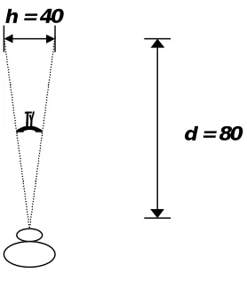
The definition of the precise position of a projection of the light from a point in the world onto a retina is determined by the direction of gaze, the fixation point, and the distance of the eye from that point. The fixation point is serviced by the fovea, and the angle between the vector from the fovea to the fixation point, and the vector from the fovea to any other point in the field of view, determines the region of the retina which services that point (see figure 3.6). The larger this angle is, the more peripheral the region of the retina is that services it. Thus can the precise position of a point on the retina be referenced. We can therefore speak of a point in the periphery as being situated at an eccentricity of 15° in the lower right quadrant, or of a point in central vision being situated at an eccentricity of 3° in the upper left quadrant. A definition of visual angle can be
found in [Olzak and Thomas 1986]. The visual angle θ is related to the distance
between two stimulus elements h, and the viewing distance d, as follows:
d
h
2
2
tan
=
θ
θ is measured in degrees, while h and d can be measured in any units, as long as the same units are used for both. When θ is small, a good approximation to the above is:
d
h
3
.
57
=
×
θ
Equation 2 [image:41.595.227.366.303.461.2]Equation 2 overestimates θ by about 1% when its true value is 10°. The peripheral parts of the retina deal with vision beyond 5°. The macula lutea is concerned with the central 5° of vision, and the fovea handles the central 1° of vision.
Figure 3.6: Calculation of Visual angle.
To summarise, visual perception results from a series of optical and neural transformations. The first visual transformation is the formation of the retinal image by the eye, which occurs as follows:
- Light from a source arrives at the cornea
- It is focused by the cornea and lens onto photoreceptors on the retina
- The photoreceptors transform light into neural signals, which are communicated
through the several layers of retinal neurons to the neurons whose output fibres constitute the optic nerve
- The neural signals are carried out of the eye by the optic nerve through the optic
disk, and are carried to the brain for further processing.
d = 80 h = 40
3.3.2
The Visual PathwaysThe visual pathways are the paths taken by nerve impulses between the eye an the brain when the retina is stimulated by light. They consist of seven structures (see figure 3.7):
- Retina
- Optic Nerve
- Optic Chiasm
- Optic Tract
- Lateral Geniculate Nucleus (LGN)
- Optic Radiations
- Visual Cortex
Figure 3.7: The Visual Pathways
Light stimulates the rods and cones of the retina. A first stage of image processing takes place in the retina itself, where there is a large number of interconnecting ganglion cells that perform basic processing such as edge-enhancement. Electrochemical messages are then passed to nerve fibres in the retina and then via the optic nerve to the optic chiasm. Here, information from the temporal (outer) half of each retina continues to the same side of the brain. Information from the nasal (inner) half of each retina crosses to the other side of the brain within the optic chiasm. The rearranged nerve fibres then pass through the optic tract to the lateral geniculate body, and on through the optic radiations to reach the visual cortex in the occipital lobe of the brain (i.e. at the back).
The cells of the retina are part of the central nervous system, and hence are called
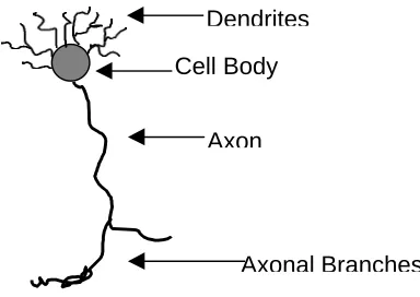
neurons. Retinal neurons have different shapes and sizes, but a typical structure is
[image:43.595.200.392.221.357.2]shown in figure 3.8. The dendrites receive input from other neurons, and the axon carries the neuron’s output onto its ultimate destination. The cell body performs whatever processing function is necessary for that type of cell.
Figure 3.8: Typical Retinal Neuron
The retina contains 3 distinct layers of cells, and two connective layers. The outer nuclear layer contains the cell bodies of the photoreceptors, i.e. the rods and cones. The axons of the photoreceptors make contact with the dendrites of the next layer of cells in the outer plexiform layer. The cell bodies of the bipolar and horizontal cells are located in the inner nuclear layer. The bipolar cells make connections onto the dendrites of the ganglion cells within the inner plexiform layer. The ganglion cell layer contains the ganglion cells, the axons of which comprise the optic nerve. These provide the only output to the brain, and therefore are the most interesting.
The ganglion cell layer has two types of cells, M cells, so-called because they project onto the M-cells of the magnocellular layer in the LGN, and P cells which project onto the P-cells in the parvocellular layer of the LGN. The M cells of the retina are sensitive to low contrasts, respond transiently, and have axons which conduct very rapidly. Hence, it is considered that these are important for motion perception. They are not wavelength-sensitive. The P cells of the retina respond to high contrasts, have a sustained reponse, and are wavelength selective. Hence, they are considered to be important for colour perception.
Cell Body
Axon
The fibres of the optic nerves carry information from the retina of each eye, and these fibres meet and cross over at the optic chiasm. The fibres from the nasal part of the retina cross over, and those from the temporal retina do not cross over, but continue on to the same hemisphere of the brain. Therefore:
• The fibres from the temporal retina of the left eye, and the fibres from the nasal retina of the right eye continue on to the left hemisphere of the brain. This means that this half of the brain looks at the right half of the field of view.
• The fibres from the nasal retina of the left eye and the fibres from the temporal retina of the right eye connect to the right hemisphere, which therefore looks at the left half of the field of view.
The visual pathway now becomes the optic tract, whose fibres terminate in the cells of the LGN. The LGN has 6 layers. The upper 4 layers, the parvocellular or P layers, have small cells, and the lower two, the magnocellular or M layers, have large cells. The two sets of cells have different destinations in the visual cortex. Most cells in the P layers are wavelength sensitive, whereas those in the M layers are not. Again, this indicates that the M layers transfer information about motion to the visual cortex, whereas the P layers transfer information about colour. Finally, the axons of the LGN cells travel in the optic radiation on to the visual cortex.
The differences in the behaviour of cells in the retina and the LGN indicates the existence of at least two parallel visual pathways, one for motion, and one for colour. In fact, there are four pathways:
1. A motion pathway 2. A dynamic form pathway 3. A colour pathway
4. A form pathway linked to colour
3.3.3
The Visual CortexThe visual cortex occupies the occipital lobe of the brain. It consists of several areas, the largest of which is the Striate Cortex. The striate cortex is a large sheet of cells at the back of the brain, so-called because the architecture of its cells, i.e. its cytoarchitecture, is very distinctive and consists of stripes. This part of the brain is also known as the primary visual cortex, or area V1, and for a long time was considered to be the only area of the brain responsible for visual perception. However, it was discovered that other areas of the brain, collectively called the pre-striate cortex, were also responsible for visual processing. These areas are referred to as areas, V2, V3 etc…Hence, we shall refer to the striate cortex as area V1 of the brain from this point onwards.
The area V1 on each side of the brain receives information about the opposite side of the field of view. The cells in the retina project in an orderly, systematic way onto the cells of the LGN, so that adjacent retinal points are mapped onto adjacent cells in the LGN. The cells in the LGN are mapped in a similarly systematic way onto the cells of area V1. However, magnification has occurred along the visual pathways, so that one retinal cell will project onto hundreds of cortical cells, which process the output of each
incoming fibre. This mapping from the retina onto area V1 is known as a topographical
map, because each part of the retina is represented in a given part of area V1.
The main function of area V1 is as a functional segretator, i.e. it selects the important information for certain sub-tasks, such as colour, motion, or form perception, and redirects the important information to the appropriate areas in the pre-striate cortex, i.e. areas V2, V3, V4, V5 and V6. Area V2 also contains the functional groupings of cells outlined above, and projects to the same specialized areas as above, namely V3, V4 and V5. Therefore, it also will send signals related to different properties of the field of view to those parts of the brain which are responsible for processing those attributes. It is also, therefore, a segregator. Area V3 lies next to B2, and receives a direct, point-to-point mapping from area V1. This means that the retina is also topographically mapped onto it. Recordings from this area of the brain have shown that the vast majority of cells are responsive to lines of a specific orientation, but show no difference in response when the colour of a stimulus is changed.
Next to V3 lies area V4. This area receives a direct input from the region of foveal representation in V1, but its predominant input is from area V2. The mapping is not so topographical as was the case from V1 to V3, but the receptive fields of cells in an area of V4 are usually in roughly the same area of the field of view. The cells in this area are heavily wavelength-specific, and only the central 40° of the retina is mapped in this area. Hence it is inferred that this is the part of the brain responsible for colour vision, and form from colour. Lying directly behind area V4 is area V5 (also called area MT). It receives a direct input from area V1. The cells in this area are all responsive to different types of motion, but the colour of the stimuli is unimportant. 90% of the cells are directionally selective. Hence, area V5 is considered to be responsible for motion perception. Finally, area V6, which is located in a different area of the brain, also receives input from area V2. The mapping from the retina is very complicated, and recently it has be suggested that one of its functions is that of space representation in the brain. All of these areas output many signals to other parts of the brain, or back into other parts of the same area.
Another pathway, the M dynamic form pathway, is derived also from the M ganglion cells of the retina. It is also relayed to the same layer of V1, and from there to area V3, both directly and via area V2. The P pathway originates in the P cells of the retina, which are relayed to the P layers of the LGN, and onto those layers of area V1 which are wavelength specific. These layers consist of “blobs” of cells, which are responsible for colour, and the areas between the blobs are called the “interblobs”, which are responsible for form. From there they divide to create a colour pathway, and a form pathway linked to colour. These two paths relay to area V4 both directly, and through area V2.
3.4 Theories of Visual Perception
As has been stated above, a wide range of approaches have been applied to explain human visual perception. An overview of the most important of these theories may be found in [Gordon 1996]. We consider two of the most significant theories, which are quite complementary to each other.
Psychophysics is a set of techniques used to study mappings between events in the
environment and levels of sensory responses, by conducting non-invasive experiments on humans. To be more specific, psychophysicists are interested in exploring thresholds, i.e. what is the minimum distance and/or size required to recognise a letter? At what point in the periphery may a gap between two objects be perceptible?
Neurophysiology is the search for explanations of perceptual phenomena by examining
From the perspective of some researchers, it may be more satisfying to deal with actual physical structures such as neural mechanisms, than with abstract (and often un-substantiated) psychological concepts. However, although advances in neurophysiology have been immense in recent years, this reductionist approach is often not sufficient to explain how the brain processes all but the most simple of visual events. Nevertheless, both approaches complement each other: psychophysical results are more secure when they can be linked to known physical structures, and the work of neurophysiologists is often motivated by the need to explain phenomena discovered in psychophysical research.
Our approach in this thesis is to discover facts about visual perception of collisions
through psychophysical experiments, but to use the results of neurophysiological
investigations both to guide the design of the experiments, and to explain our findings.
3.5 Collision Perception
To determine the factors which influence a viewer's perception of a collision, and the extent of their contribution, we must first try isolating these factors, and testing them individually. We need to carefully consider each potential factor, and decide on the best way to test its effects. This will lead to a set of psychophysical experiments, the results of which will be used to schedule collision testing in our application.
The list of potential factors includes:
1. Type of collision event 2. Eccentricity
3. Separation 4. Location 5. Orientation
6. Motion: velocity and direction 7. Presence/Number of distractors
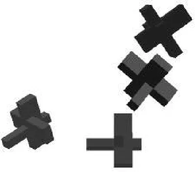
Figure 3.9: Different types of collision events
1: Objects approach
2: Normal Response. Objects touch, then reverse
3: Response Anomaly (a) Objects repulse
3.5.1
Type of collision eventIn the applications being considered, three types of collisions may occur (see figure 3.9):
- "True" collisions, where entities touch, the collision is detected, and fully accurate collision response occurs. We may consider this as being the control situation for experimental purposes.
- Interpenetrations, where the entities also touch, but the collision is not detected or is ignored by the application. The entities are therefore allowed to continue on their previous path, even though it causes them to merge into each other to a greater or lesser degree.
- Repulsions, where the entities are close to each other but have not actually touched. In this case the application decides to take the chance that they are actually touching, and accepts this situation as a true collision. This may then cause the entities to change their paths, causing a repulsion effect.
The application can control which type of collision anomaly will occur most often, if not always. It could be argued that a detailed study should be conducted into which type of anomaly is most disturbing to the viewer. However, there are certain points to be made in favour of allowing only repulsions to occur: