BASIC PROGRAM'M,ING
Preface
This manual is a basic text in programming the Univac II Data-Automation System. It is an introduction to the foremost data processing system yet developed, and to dynamic and advanced concepts in the field of data processing.
Study of this manual will also acquaint you with the language of the Univac II Data Automation System, and the principles of efficient Systems Design so'that maximum utilization of the capabilities of the Univac II Data Automation System can be achieved.
Although intended primarily as a text for a course of instruction conducted by the Remington Rand Univac Training Department, it is recognized that many may not have the opportunity to attend such a formal training course. With this in mind, each topic has been introduced with a thorough explanation followed by illu stra-tive examples and student exercises.
Table
Of Contents
I INTRODUCTION
Data Processing Areas in Business . Present Electronic Computer Applications. Data Processing Equipment . . . . Electronic Computer Classifications . . . .
II ELEMENTS OF THE UNIVAC DATA AUTOMATION SYSTEM
Input-Output Units . . . . The Univac Central Computer ..
The Memory Unit . . . The Control Unit The Arithmetic Unit
III INTRODUCTION TO CODING
Arithmetic Instructions - List A Illustrative Example . . . . Student Exercises . . . .
, Arithmetic Instructions - List B . . . .
The Decimal Point . . . .
PAGE
1
2 6 9
12
17 23 26
28 3.1 32
35
37
44 47 47
50
Rule for Addition and Subtraction. . . 50
Rule for Multiplication. . . 51
Rule for Division. . . 51
Student Exercises. . . 52
The Control Unit. . . 53
Three Stage Cycle of Operation . . . .. 54
Transfer of Control Instructions. . . 63
Illustrative Example. . . 67
IV INTRODUCTION TO FLOW CHARTS
Illustrative Example . . . .
Student Exercises. . . . . . .
Summary . . . .
V MODIIFICATION OF INSTRUCTIONS
Iterative Coding . . . . Iterative Flow Chart Symbols
Illustrative Example. . . .. . .. Arithmetic Instructions - List C .
Student Exercises . . . . Function Table Look-Up . . . .
Illustrative Example . . . . Function Table Look-Up in Flow Charts . . . . Shift Instructions . . . .
PAGE
72 \/
78 . . . . • 80 . . . . 82
84 88 93 94 96 99 . . . . 99 99
101 102
Student Exercises. . . 107
Summary. . . 107
VI ITEM PROCESSING 109
The Item . . . . . The Field . . . .
Representing Fields on Flow Charts .. Illustrative Example.
Working Storage . . . . Item Registers . . . .
Student Exercise . . . . Field Selection Instructions .
Illustrative Example . . . .
109 109 110 111 113 11,5 121 122 124 Student Exercises. . . 125 Summary . . . .'. . . . . 128
VrI SUBROUTINES AND VARIABLE CONNECTORS 129
Common Subroutines. . . . 129
Illustrative Example. . 129
Variable Connectors . . .
Student Exercise . . . . Subr outines . . . .
PAGE
VIII DETAILED DESCRIPTION OF INSTRUCTIONS 147
Transfer of Control Instructions . . . 147
Shift Instructions . . . 149
Multiword Transfer Instructions. . . 149
Arithmetic Instructions. . . .. 152
Overflow. . . .. 155
Undesired Overflow . . . . Student Exercises .. Summary . . . . IX INPUT - OUTPUT 162 162 163 166 Character Representation. . . 167
The Uniservo . . . 169
Buffering and Backward Read . . . 170
Tape Instructions. . . . . . . Tape Instructions on Flow Charts . . . .. Sentinels . . . 0 • • • • • • • •
The Instruction Tape . . . . 0 • • 0 • • • • • • • • • • 0 • • • • • • Servo Delta . . . . 0 • • •
Illustrative Example . 0 • • • • • • 0 • • • • • • • Student Exerc ise . . . . . . . . . 0 • • • •
Summary . . . . X TIMING AND EFFICIENT USE OF BUFFERS Preselection . . . . Illustrative Example .. Student Exercise . . . . 0 • • • • • • • • • • • • •
Routine Timing . . . . Timing a Straight Line Routine . . . . 172 176 176 177 177 178 186 187 188 189 189 196 196 199 Timing an Iterative Routine. . . 200
Timing a Branch Routine. . . 200
Tape Instructions. . . .. . . . .. 201
Timing a Routine Involving Tape. . . ... 203
Graphical Representation . . . . 207
Timing a Branch Routine Involving Tape. . . 208
Standy Block Method • • • • • •• . . . 212
XI SUPERVISORY CONTROL PANEL OPERATIONS
The 10m Instruction . . . . Conditional Transfer Breakpoints . . . . Printing from the Supervisory Control Panel
The All Conditional Transfer Breakpoint Selector Button Interrupted Operation. . . .
Other Breakpoints . . . . Manual Alteration of Instructions in the Memory The Fill Operation .. .
SCICR . . . . Generating Data . . . . . Debugging Proc edure .. . The Empty Operation .
Memory Dump . . . . Verifying the Output . . . .
Summary of Procedures to Follow for Test Running a Routine Sumnlary . . . .
XI I SORTING AND MERGING
Collation . . . . Digital Sort . . . .
PAG E 216 217 217 218 219 220 221 221 221 222 222 222 223 223 224 224 225 227 228 233 Function Table Sort . . . 236
XI I I PREPARATION AND DISPOSITION OF DATA
Keyboard to Tape Recording . . . . Univac Unityper . . . . . . .
Univac Verifier . .. . . . . . . Card-To-Tape Recording . . . .
Univac 80 Column Card-to-Tape Converter Univac 90 Column Card-to-Tape Converter Paper to Magnetic Tape Recording . . . . Univac High..;Speed Printer. . . . . . . Tape to Punched Cards . . . . Magnetic to Paper Tape . .
XIV SYSTEMS DESIGN
Choosing the Application . . . .
PAGE
252
252
Preparing the Program . . . .. 253
Input Verification. . . .. 21:)6 Item Rearranging . . . . " . . . , . . . 21>7 Output Preparation . . . " . . . • . . . .. 258
The Process Chart . . . .. 21>8 Time Estimation . . . ..
264-Computer Running Time. • . . • . . • . . . • . . . .. 264
Unityping . . . .. 264
V'erifying . . . .. 264
Card-to-Tape . . . .. 264
Univac High-Speed Printer . . . • . . . .. 265
Approximate Time Estimating . . . .. 265
Planning the Cut-Over . . . .. 266
Future Planning. . . .. 267
XV OPERATIONAL ROUTINES 268 l'ape Summary. . . • . . . .. 269
l"able Look Up . . . . . • . . . • . . . • •. 273
Explosion . . . '. . . • . . . .. 276
XVI STORAGE OF INFORMATION 282 Mercury Tank . . . . 283
Magnetic Core. . . . • . . . .' . . . • • • • • . . .. 284
The Memory. . . • • . . . • . . . .. 286
Summary. . . • . . . • . . . . • .. 287
XV I I MANIPULATION OF INFORMATION 288 Representation of Information. . . • • • • • • • • • • • . • . . . . . . • • . .. 288
Binary Addition. • • • • • . • • . . • • . . • .. . • • . • . • • . . . • ••. 290
Addition of Two Numbers with Opposite Signs . . . • . . . . . 290
The Arithmetic Unit. . • . . . • . . • . • • • • • • • • • . • • • . • • • • • • •• 293
Coded Binary . • • . • • • • • • • • • • • • • • • • • . • • • • • . • • • • • • • •• 294 Excess Three Arithmetic . • • • • • . . • . • . . . .. 295
Student Exercises. . . • . . . • • . . .. 297
PAGE
Logical Building Blocks. • . • . • • • . . • • • • • . . . 298
Logical Circuits . . . • • • . . • . . . ' . . . • . . • 301
Magnitude Comparator. • . . . • • . • . • . . . • . . . 302
Half Adder. • • • • • . • • • • • • • . • . • • • • • • . . . • • . . . 302
Binary Adder . • . . • . . • . . • . . . ' • • . . . • . . • . 303
Equality Comparator. . • • . • . . . • • • . . . 304
XV I I I INSURING ACC URACY OF PROCESSING Operator Accuracy • . . • • . . • . . • • . . • • . . . 301) 306 Rerun. . . . • . . . • • . . . . • . . . • . . • • • . . . 306
Computer Accuracy. . . • . . . . • . . . 306
Types of Failures. . . 307
Error Detection . . . 307
Programmed Error Detection Diagnostic Routines . . . • • • • 307
Duplicate Runs . . . 308
Programmed Checks . • . • . . . • . . . 308
Built in Checks. . . • . • • • . . . • . . . . . • . . . • • . . • . . . 309
Built in Checks of the Univac Central Computer . . . • . . . . 309
Odd Even Check. . . • • . . .• . . . • . . . . . . • • . • • . . . • 309
Duplicated Circuitry • . . . . • • . . . • . . . . • . . . . • • . . . . • . • . . 3 10 Counting Checks . . . • • • • • . • • '" • . • . . . • • . . . • . . . • 310
Logical Checks. • • • . • . • . • . . . • . • . • • • • • • • . • • . • • . • 310
chapter
1
Introduction
DATA PROCESSING AREAS IN BUSINESS
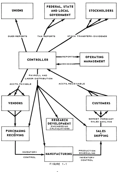
A first step in a study of electronic computers is to survey the areas of business operations wherein a computer may become a useful managerial tool. These areas are called data processing areas. In its day-to-day functioning a manufacturing concern is composed of myriad channels through which money and material flow in fulfillment of the company's obligations to its stockholders, employees, vendors, customer and the government. From a data processing point of view, these areas are concerned with management's attempts to record, measure and effectively con-trol this flow. Because of its broad yet familiar activities the manufacturing com-pany's activities will be considered. Figure 1-1 is a generalized block diagram of a typical manufacturing company and its environment.
The most common data processing areas have been indicated on the chart. A very brief description of each is listed below.
1
UNIVAC®II
A TYPICAL MANUFACTURING ORGANIZATION
AND ITS DATA PROCESSING ENVIRONMENT
UNIONS
DUES REPORTS
ACCTS. PAYABLE
VENDORS
PURCHASING • RECEIVING
FEDERAL, STATE AND LOCAL
GOVERNMENT
STOCKHOLDERS
TAX REPORTS STOCK TRANSFERS-DIVIDENDS
OPERATING
MANAGEME..-T
ACCTS. RECEIVAB LE
ENGINEERING CALCULATIONS
CUSTOMERS
MARKET FORECAST
SALES
•
SHIPPINGPRODUCTION INVENTORY
.... ---IIiIIII..-.I
MANU FACT U R ING ~_S_C_H_E_D_U_L_I_NG_ ...CONTROL INVENTORY
MARKET FORECASTING AND SALES ANALYSIS:
To attempt to find the beginning of the movement through the channels pictured would be to search for the beginning of a circle because of the multitudipous cross-references and interdependencies which exist. From . the point at which planning for the next year commences, howeverl a certain sequence does follow.
At that point the big question is, "How good will the new year be?". The answer can be found by making a reliable sales forecast to serve as a basis upon which all operational planning will be laid.
The past sales history is essential to such a forecast. Thus, many concerns break down their sales as often as once per week according to the products sold, the regions in which they were sold, the dollar values of the sale, the percentage gross and/ or net profit obtained and other significant criteria. In addition to predicating
any immediate action which needs to be taken, such reports, if compiled over a
period of years, will yield information on the seasonal and regional fluctuations of the sales of various products.
A further study of such a sales analysis may bring out some revealing correlation between the concern's sales and the general business trends and cycles, customer activities and similarly relevant factors. Such correlations are not always easy to find; but once discovered, they offer the means of making a reliable forecast of the sale of each product in each marketing area. An evaluation of the market forecast will affect the budget and production levels to be maintained during the year.
PRODUCTION SCHEDULING:
The sales forecast and any adjustments to it which may be necessary as the year progresses are the sources of the production orders. The production orders indicate the date of completion and size of each batch of every product to be manu factured. Referencing these orders against a bill of materials listing is then the basis of the production scheduling operation. This listing contains the material, machines and time required for the completion of each phase in the manufacture of the product. Working backwards from the t«due date" it is possible to list the times at which materials and machines must be available if the due date is to be met. Proper planning is essential since any misscheduling of machine requirements may result in delays and extra production expense for overtime, or idle machinery and idle men. In addition to yielding a machine schedule, the bill of materials listing yields the requisitions for the total raw material requirements and the time in the produc-tion line at which they must be available.
3
INVENTORY CONTROL:
From the bill of materials listing, information is also obtained for the inventory control. As a by-product of the machine scheduling, the quantities of raw materials needed during each manufacturing phase are also determined. These raw material requirements are used for the publication of requisitions. In addition, they are com-pared to the current inventory level of the material and posted to it. If the reorder level is reached, production or purchasing orders, depending on whether the material is processed within the company or purchased, are issued in order to replenish the stock. Proper use of reorder levels can offer considerable savings by accurate control of the minimum inventory level to be maintained. Accurate inventory con-trol is essential in reducing the capital investments and storage obsolescence costs of large inventories, or the costs of emergency reorders and delays resulting from shortages.
ACCOUNTS PAYABLE:
The accounts payable operation IS initiated by the receipt of an invoice from the
vendor. This invoice is first checked for amounts billed against quantities received and priced against the current price list. Then, although immediate payment of all accurate invoices is possible, payment is usually postponed temporarily to allow further use to be made of the available cash. Such unpaid invoices are listed on the accounts payable ledger. Cash balances and the efficient use of any discount privileges determine the time for selection from this ledger for payment. Checks are produced and appropriate entries made in the vendor's account. Information a vailable may also be extracted for such things as general ledger and property accounting, and reports on vendor activity.
PAYROLL AND LABOR DISTRIBUTIONS:
This area is commonly the most highly mechanized data processing area in busi-ness today. In spite of the fact that all payrolls are designed primarily to produce paychecks, the variety in important payroll details caused by unusual or individual labor contracts, differing local and state regulations and plant policies preclude a complete uniformity of description. With this precautionary statement in mind, consider payroll data processing to be divided into three parts: determination of gross pay, computation of net pay from the gross, and labor distribution.
payroll. Here gross pay is a fixed, constant amount for each pay p,eriod agreed to in advance by the employee and employer . Usually no calculations are necessary, and the determination of gross pay amounts to simply calling for it from the em-ployee's record. In most cases, however, the determination of gross pay is an in-volved process. Gross pay is more often based upon the number of hours worked in
each of several hourly rate categories (regular and overtime factor~) during the pay
period. This may be modified in many plants to include bonus or efficiency pay-ments determined by the output of groups of workers or by a piecework schedule. The net pay calculation involves the computation of tax deductions imposed by state, local and federal governments and such other deductions, usually variable in amount from one pay period to the next, as specified by union contracts and fringe benefits or employee options. The end product of the net pay calculations is a series of paychecks (or pay slips if payment is by cash) and various payroll registers listing gross and net pay and the several deductions. In addition to these, the individual earnings record must be updated for end-of-quarter and end-of-year government tax reports.
The labor distribution phase is used by management to establish product costs and selling prices. Gross-pay and hours-worked data for each employee, established in the gross pay phase, are distributed to each product, account or activity he has engaged in during the pay period. These are then summarized to produce labor costs for each of the distributed categories.
TAX REPORTS - UNION DUES REPORTS, ETC.:
Under present labor-management practices, management assumes many of the em-ployee's obligations to his environment. Taxes, union dues and various voluntary deductions are withheld. The necessity arises for the firm to make reports to the government, union dues reports to the unions, hospitalization and insurance re-ports, etc. The information for such reports is available from the payroll process-ing itse~f.
Year-to-date totals of gross pay, income tax withheld and FICA tax are sufficient for the preparation of W-2 forms. Similarly a compilation from the employee files and payroll processing results is all that is necessary in the preparation of most other reports.
5
UNIVAC®IIACCOUNTS RECEIVABLE:
The accounts receivable operation commences when a shipping document is re-ceived indicating that delivery of an order has been made. Products listed on this document are priced and the shipment is extended to produce the invoice sent to the customer. At the same time, the total dollar charge is posted to the customer's records on the accounts receivable ledger.
This ledger is often scanped daily. Cash receipts and any earned discounts are credited to it. Appropriate information is entered into the customers' credit history. Ageing accounts are extracted, checked, their credit history examined and appropri-ate action is taken. At the end of the month, the information present is compiled to form monthly statements, which also may be sent to the customer.
STOCK DIVIDENDS AND TRANSFERS:
In addition to the data processing involved in the manufacturing company's obliga-tions to supplier and customer, employees and government, some arise from its basic obligations to the stockholders, namely, allowing them a voice in the manage-ment and a share in the profits.
Up-to-date listings of holders are essential to the proper satisfaction of these obligations. Consequently the holder listings must be periodically maintained to assure that they reflect the latest results of all stock issues, cancellations and transfers. When a dividend is declared, it is then only necessary to select the owners as of that date from the listing and multiply the dividend rate by the number of their shares to make the proper disbursement. Similarly a scanning of this list is sufficient when it is necessary to print and distribute the proxy ballots for the annual stockholders meeting. Year-to-date dividends paid and other information on this listing may be employed in the preparation of the year-end state and federal tax reports and of any statistical reports desired.
PRESENT ELECTRONIC COMPUTER APPLICATIONS
This list is intended to be indicative and not exhaustive due to the constantly in-creasing number of installations and to the continuing expansion of applications at current installations.
ADVERTISING:
Calculation of sales volume predictions based upon past sales, employing least squares fit technique; monthly tabulation of editorial lineage by pre-determined classifications.
AIRCRAFT MANUFACTURING:
Payroll, labor distribution, efficiency ratings; engineering and scientific prob-lems including trajectory and matrix calculations.
CHEMICAL MANUFACTURING:
Payroll, engineering problems, central billing, inventory and production con-trol, accounts receivable, sales statistics. solution of differential equations.
El,ECTR ICAl AND ELECTRONIC MANU FACTUR IN G:
Production control including scheduling, inventory control, preparation of shipping documents, production scheduling and market forecast; financial con-trol including payroll, preparation of invoices, cost and general ledger account-ing and budget preparation.
GOVERNMENT AGENCIES:
HEADQUARTERS UNITED STATES AIR FORCE - Aircraft scheduling, budg-eting, determination of supply requirements, calculations of projected aircraft engine inventory for several engine types.
AIR MATERIEL COMMAND - Payroll, procurement, supply, contro'! -- fiscal and budget.
ATOMIC ENERGY COMMISSION - Problems arising In the design and con-struction of power and research reactors; problems in nuclear physics.
7
BUREAU OF CENSUS - Population statistics; seasonal business trends.
DEFENSE DEPARTMENT - Tables of phased requirements in personnel and material for the support of operational programs.
WEATHER BUREAU - The circulation acceleration of atmosphere at different levels computed from radiosonde data.
GENERAL INDUSTRIAL:
Payroll, cost distribution, stores accounting, market forecasting; production control including material scheduling, inventory control and production sched-uling; general accounting including invoicing, cost and general ledger account-ing, and budget preparation; capital accounting; stock transfer; prediction of the variability of product mixture based on changing components employing regression techniques; material utilization analysis; explosion and summariza-tion of parts and sub-assemblies for producsummariza-tion orders.
INSURANCE COMPANIES:
Premium billing and accounting, agents' commission payments, dividend cal-culation, policy loan accounting, actuarial computation, market analysis, annual statement preparation, mortgage loan billing, file maintenance, agency statistics, field auditing, policy loans, reserve valuation, payroll, check issue, actuarial statistics.
OIL COMPANIES:
Oil payment accounting, gas payment accounting, payroll, bulk station check-ing, sales and stock statistics, matrix calculations, calculations for optimiza-tion of amount of end product from raw input.
PUBLIC UTILITIES:
LIGHT AND GAS - Billing, payroll, matrix calculations, computation of utility rate tables.
TRANSPORTATION .. Revenue, material, vehicle accounting; payroll, person-nel records, cost distribution, plant accounting.
PUBLISHING:
Advertising space and sales analysis; preparation of mailing list using statis-tical sampling technique.
RAILROADS:
Freight revenue accounting, payrolt capital accounting, stock transfer, labor distribution, I.C.C. reports.
DATA PROCESSING EQUIPMENT
In the preceding section, the general data processing areas in industry were briefly described, and some of the applications for which computers are currently being utilized were listed. To the beginning student of electronic data processing many of these areas must have appeared so unrelated to each other as to warrant objec-tions to their being lumped together as being only different aspects of a common operation. Prior to the advent of electronic computers, management usually be-lieved there were no common grounds between them -- that payroll and premium billing are too different to allow their study b'y general techniques. The desire to apply electronic computers to business problems required computer designers to search out the fact that payroll and premium hilling were indeed susceptible to study by a universal technique. This means that a generalized description of data processing can be developed without the necessity of studying each individual area of application. Figure 1-2 is a general block diagram of a data processing system.
DATA GATHERING UNITS FOR VARIABLE INFORMATION
MASTER DATA FILES
DATA PROCESSOR
FIGURE 1.'2
9
PERIODIC REPORTS OR OTHER PR I NTEi> OUTPUTS
Each of the data processing areas described above consists of the four elements shown in Figure 1-2. A data processing system is best described by its outputs. These are the various reports, summaries, statistics, bills, checks, invoices, etc., either required by management or government, or which are a necessary part of the detailed operation of the company. The information required on these printed out-puts and their frequency establish the general requirements for the remaining three elements.
The inputs to the data processing system from which the output reports are to be compiled usually consist of two types; master data that remains essentially un-changed from one reporting cycle to the next or which changes in a known and fixed way; and variable information which is produced by the unpredictable activi-ties of the business. Master data is the permanent information records containing identifying and historical data about the individual, account, item, product or service being reported. Examples of master data are: names and addresses, account numbers, current credits and debits, running inventories, wear-out rates, etc. Variable information is data introduced to the data processing system reflecting
current operations. It is generated by human activity and is thus essentially
un-predictable. Examples of variable information are: the hours worked by an employee, receipts, expenditures, sales, shipments, etc. Since the transaction producing these variables are often physically dispersed (coming from different departments or branch offices) some means of gathering the data for injection into the system is required.
The data processor IS the converter of master and variable data into the output
reports. As the block diagram indicates it also posts changes, when necessary, to the master data files. These changes are introduced to the processor through essentially the same data gathering units which are used for the variable information.
The data processor may be a clerical staff or an electronic computer with all gradations between these two extremes. In order to be able to produce the output reports, the data processor must be able to
1. read documents,
:2. record documen ts and reports, 3. sort and classify data,
4. calculate,
5. make simple decisions.
MANUAL METHODS:
The postwar growth in American business has been characterized by streamlining factory and production methods in order to achieve high production at a lower unit cost. Office management, howe.ver, has increased the data processing output re-quired by this higher factory production more by simply increasing the clerical force than by improving unit costs through cleaning up or redesigning the data processing system. Admittedly system redesign is a difficult and involved task, requiring a careful study of each data processing system extant so that overlapping or useless operations may be removed.
For low volume work the human being has the considerable advantage of requiring no translation of business records or transactions, and his methods can be changed with relative ease. He is, however, susceptible to error especially if the work is
highly routine or if the work load is heavy; his speed of calculating, posting and
printing is slow; and for large volume work his cost is disproportionately high.
KEY DRIVEN DEVICES:
The next step in the direction of the automatic office is in improving a manual system by adding key-driven devices. This includes such standard office equip-ment as typewriters, adding machines, calculators and accounting machines. In general, these devices mechanize the calculation and printing functions of the
data proce~sor. In their simplest form, these key driven devices are either a
type-writer performing the printing function only or an adding machine performing addi-tion or subtracaddi-tion funcaddi-tions. By appropriately combining the print and calculate functions, and further, by building in a more elaborate control mechanism which can govern addition and subtraction, a class 'Of calculators capable of performing aU four arithmetic operations and the automatic printing of results has been pro-duced and is in common use.
A further extension of the printing calculator principle to provide greater flexibili-ty in the format of printed results has led to the flexibili-typical accounting machine. A
trend of very recent origin is the connection to th~se accounting machines of 9a per
tape punches which provide a means of direct communication to other types of calculating and computing mechanisms without the need for re-transcription of data. These devices are members of a common language data processing system.
For moderate volumes of data involving relatively short sequences of calculations, unit cost is low, speed and accuracy is greater than manual methods, and trained and experienced personnel are available. Changes in procedure and forms can be
11
UNIVAC®IIaccommodated with relative ease. Machines with punched paper tape output provide a means for further calculations to be done without the necessity for manual re-en-try of data.
One disadvantage of key driven devices is that data translation to a machine read-able form is necessary, with translation consisting of the entry of data into a key-board. Another disadvantage is that the sorting and classifying of data, decision making and the sequencing of operations must be done by human intervention.
PUNCHED CARD MACHINES:
Prior to 1953 punched card ~quipment, commonly referred to as tabulating
ment, marked the apex of office auto,mation. The general plan of tabulating equip-ment is to provide specialized machines which perform each of the five basic elements of the requirements listed for a data processor, although in some cases a single machine may perform several such functions. These machines are sorters, tabulators, calculators, interpreters, collators, key punches a.nd reproducers. These machines form a common language group. The punched card serves as a data com-munication and storage medium.
As compared with key-punch or manual methods punched card machines have speed,' accuracy, and low unit cost for relatively large volumes of work as well as permit-ting variety and completeness in reports. Changes in procedure and forms may be relatively difficult, and the scope of operations performed is limited so that ex-ceptions must be handled manually. There is in addition the arbitrary limitation of record size to either 80 or 90 digits or multiples of 80 or 90 digits.
ELECTRONIC COMPUTER CLASSIFICATION'S:
IN-LINE COMPUTERS:
Although the logical roots of modern electronic computers extend back over a century, the advent of their application to office automation was in 1953. Since then, the development of electronic data processors (or computers for short) has
proceeded in two main directions: the fC in-line" or ureal-time" computers
one of economics. Considerations of economic design has led to the development of computers intended for but not restricted to each mode, and this has often led to the equipment itself being identified as in-line or off-line.
An in-line application is one in which transaction information reflecting current activity is introduced into the data processor as it occurs resulting in the immediate modification of the master data record. Thus, these master records are always up to date. Thus modification of these master records is in effect directly t t in the line"
of the company's operations.
The basis for the in-line computer is the development of relatively high-speed storage facilities of exceptionally large capacities capable of storing the entire master file of data processing area. Further, this large capacity file storage must make available to the other components of the computer its stored information at a
very rapid rate.
Once the existence of this type of storage became available, it was possible to connect the data gathering units to the computer so that transactions could be entered directly into the computer, which can then consult the master file informa-with minimum delay. The calculations or other processing is done on an item-by-item basis, that is, on demand. Through the use of a stored program principle, the computer can sort and classify data, perform long sequences of involved calcula-tions, and can exercise simple decisions in a completely automatic manner. Aux-iliary units attached to the computer can be used to print final results or reports of such calculations if desired.
An example of this type of computer is the airline reservations system. The Univac File Computer is an example of equipment which can be applied to a variety of
in-line operations. An obvious advantage of in-in-line computers is that it permits the
coupling of ttpo.int of sale recording" with direct inHuiry units. Where fully current information in readily available form on each account or item is essential, the in-line computer offers high-speed and accuracy of operation. Another feature is that the task of pre- sorting the batches of transaction data (which is a characteristic of the off-line applications) is unnecessary with these so-called random access
memories.
One limitation of these applications is that the volume of transactions of a particu-lar type must justify a special piece of equipment. However, most business applica-tions will require that the eJectronic system perform other operaapplica-tions than simply the modification of master records by the posting of transactions - such operations as records of the posting, order issuance and summary report preparation. Hence, this equipment must be made adaptable for off-line operations as well as in-line.
13
Another problem which may arise with these computers is caused by the expansion
and contraction of the master file. If an electronic device is purchased of just the
size necessary to store the current master file, difficulty arises when adding new i terns to the file, especially when a record must be fitted to an already full
sec-tion. Contrasted to this, the deletion of items causes gaps. If a device is purchased
sufficiently large to hold all possible numbers, a great many more critical gaps may occur in the areas of inactive and non-existent items.
In general the in-line computer is inflexible'in the numbering or identifying of data for the items in the master file, and a further difficulty is that there are no provi-sions for the searching of files by other than the key criterion on which the items have been stored. For example, the master records in a stock inventory applica-tion may be stored by the stock number key, yet an inquiry or a summarizaapplica-tion may be required on a selected supplier's code.
The major subject of this manual is the application of the off-line computer, al-though many of the techniques illustrated are applicable to in-line computers.
OFF-LINE COMPUTERS
A major area of data automation interest is in the application of the off-line elec-tronic computer. Instead of handling each transaction as it occurs (as would be the case for the in-line computer) transactions are batched until an economical work load is gathered. These batched transactions are then run against the master files to produce the desired reports, documents, or posting operations. While data is accumulating for one .aspect of an operation, another operation isbeing perform-ed on the computer.
As contrasted with the in-line computer, the off-line computer cannot be- used economically on a demand basis. This is primarily because the media for storing the large volume master files of a business operation are generally magnetic tapes. Access to information on these tapes must be accomplished in a sequential fashion rather than in a random fashion as would be required if the computer is to be used on demand. This is, of course, not a limitation of flexibility of the computer, but is simply a matter of economics.
The instructions recognized by the computer permit it to ,perform: the reading of documents after they have been transcribed onto a magnetic tape, the writing of documents or reports, sorting and classifying information, calculating and exer-cising simple decisions as required.
The off-line computer incorporates the advantages of the in-line system in per-forming its operations at high-speed with a great degree of accuracy and at low unit cost for high volume processing; but it eliminates one disadvantage in that file contraction and expansion is simply a matter of the amount of magnetic tape used (a much more economical storage medium), and its flexibility is such that all aspects of a data processing area can be automated. The fact that a batching operation is required for efficient use (and that completely current files are thereby precluded) is meliorated by the speed at which operations are performed -- so that, in general, files are more current than would be possible with any other data pro-cessing system except an in-line computer relegated exclusively to one application.
In contrasting in-line equipment with off-line equipment, it has been implied that
existing in-line equipment is most often cc special purpose". The Univac
File-Com-puter is an example of one comFile-Com-puter which is not U special purpose" and yet may
be used in line. The term tc general purpose" is applied to systems which can be
applied to any data processing area for which the computer is given appropriate instructions. General purpose computers are characterized by having stored pro-grams of alterable instructions.
ANALOGUE AND DIGITAL COMPUTERS
There are two methods of measuring quantities, and two types of computers de-signed around the two methods. Quantities are represented with numbers or with comparisons to the quantity to be represented. A man says a fish is 12 inches long or indicates its length with the distance between extended palms. Computers which count with numbers are called digital computers and those which operate without counting, but derive their results directly from the magnitudes of electric currents, voltages, or shaft rotations, are called analogue computers. Digital com-puters, exclusively, are used for data processing. These systems employ an in-dividual code for each number and for each letter of the alphabet, and often for
punctation marks, for abbreviations such as
$,
%, & etc., and other symbols.15
COMMERCIAL AND SCIENTIFIC COMPUTERS
While the Univac II Data Automation System IS frequently employed for the
solu-tion of scientific problems, its more common use is for business applicasolu-tions such as the computation of large payrolls, inventories, etc. These problems are charac-terized by the vast quantity of input and output data. Very few calculations must be performed to compute each individual paycheck; the problem lies in the number of pay checks to be computed. The name t t data processing" is applied to these
problems.
Scientific problems, on the other hand, involve small amounts of information upon which a vast number of operations must be performed. Because of this difference in the nature of business and scientific problems, there are computers designed for emphasis in each field ..
chapter
2
Elements of the Univac
Data Automation System
To determine the elements of a data processing system, examine the steps in the manual solution of a data processing application. Consider a company that- keeps a record of its stock in a ledger. Each day a clerk is supplied with a sales form. On the basis of the form the clerk brings the inventory up to date by writing a new column in the ledger.
17
UNIVAC®//INPUT~
PROCESSING~
OUTPUT~
FIGURE 2· 1
To do the processing the man goes through certain st.eps .
•
READ THE FIRST INVENTORY STOCK NUMBER
READ THE NEXT ONE
IS THERE A SALES ITEM FOR IT?
YES
NO
WRITE THE INVENTORY
_-II·.~itltQUANTITY IN THE
~--~~---~ HEW COLUMN
SUBTRACT THE SALES QUANTITY FROM THE
INVENT-ORY QUANTITY
IS THIS THE LAST INVENTORY
STOCK NUMBER?
. .
---~~NO~-~IY~E~S~~
PUT THE LEDGER
AWAY
SUBTRACT THE
Thus, the clerk must be able to perform arithmetic; SALES QUANTITY
FROM THE
INVENT-FIGURE 2·3
he must be able to make logical decisions;
FIGURE 2.4
he must be able to remember information;
READ THE FIRST INVENTORY STOCK NUMBER
IS THERE A SALES ITEM FOR IT?
NO
ORY QUANTITY
IS THERE A SALES ITEM FOR IT?
NO
WRITE THE INVENTORY _ . . ~ QUANT I TY I,N THE
~---~---~ NEW COLUMN
READ THE NEXT ONE
SUBTRACT THE SALES QUANTITY FROM THE
INVENT-ORY QUANTITY
F I'GURE 2·5
19
UNIVAC®IIand he must either execute the steps in the sequence shown or do something logically equivalent to this sequence of steps.
..liliiii
THEN, .... DO THIS
+
THEN
....
....
DO ORTH IS
I
THIS.,
,.
THEN, DO THIS
THEN, DO THIS
~ ~
DO THIS
F I'GURE '2·6
This example involves six elements.
1 Input 2 Arithmetic
3 Logical Decisions
4 Memory 5 Control 6 Output
FIRST, DO THIS
THEN,
....
DO THIS
....
~ ~
,
THEN
OR NOW, STOP
I
THIS+
S Toe K 1--..,..--r--,-...,....~---.---1
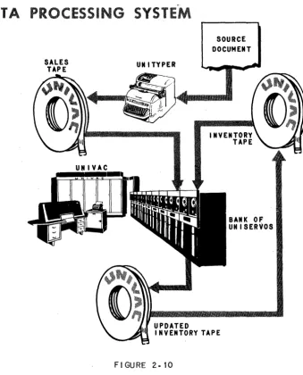
SOURCE DOCUMENT
UNITYPER
F I'GURE '2· 7
INVENTORY
TAPE
Instead of a sales form, a sales tape is produced daily, also by the Unityper. In-stead of the clerk, the Univac Central Computer does the processing.
UNIVAC
PROCESSING
FIGURE 2·8
21
UNIVAC®//The inventory tape is read by means of a tape handling mechanism called a Unis~rvo.
UNISERVO
FIGURE 2.9
The sales tape is read from another Uniservo.
The clerk brought the inventory up to date by writing a new column in the ledger. The Central Computer brings the inventory up to date by writing an updated inven-tory tape on a third Uniservo.
In this application the Central Computer requires three Uniservos - two for reading and one for writing. Reading and writing requirements vary from application to application. To provide maximum flexibility, the Central Computer has access to a bank of 16 Uniservps, any of which can be used for reading or writing.
In the manual solution, the column the clerk writes in the ledger on anyone day, that is, the inventory output, becomes the inventory input on the next day. The sales form continues to originate each day from outside the data processing sys-tem.
DATA PR CESSIN
SALES TAPE
UNIVAC
INPUT OUTPUT UNITS
SYSTE
UNITYPER
UPDATED
SOURCE DOCUMENT
BANK OF UNISERVOS
I NVENTORY TAPE
FIGURE 2. 10
In many cases, input data does not come, and output data is not desired, in tape form. The Univac Data Automation System includes several input units to convert data from some other form to tape, and output units to convert tape data to some other form.
INPUT UNITS
The Unityper has already been discussed as an input unit.
23
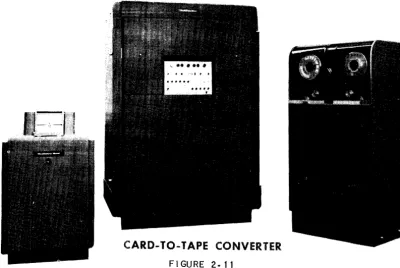
The Univac Card-to-Tape Converter converts data punched on cards to tape.
CARD-TO-TAPE CONVERTER
FIGURE 2.11
The lJnivac PTM converts data punched on paper tape to magnetic tape.
,
FIGURE 2.12
, • '. * '. ''t".-.
'. " "" ~, '*" ....
":,->.fI '\lJI"'iI¥~ v'~~'iI "'<i~GI. ~
•••••••••••••• ... »
OUTPUT UNITS
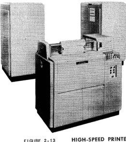
The Univac High-Speed Printer.
FIGURE 2· 13
HIGH-SPEED PRINTER
The Univac Tape-to-Card Converter.
FI'GURE 2.14
TAPE -TO-
CARD CONVERTER
25
UNIVAC®IIThe Univac MTP converts magnetic to paper tape.
FI GURE 2.15
MAGNETIC -TO-PAPER TAPE CONVERTER
KEYBOARD INPUT OUTPUT
Besides using tape, the Central Computer can also accept and produce small volume data directly by means of a keyboard and a typewriter.
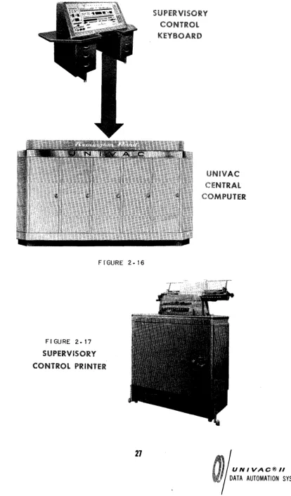
The Central Computer accepts data directly from an operator's key strokes on the Supervisory Control Keyboard.
The Central Computer produces printed data directly on the Supervisory Control Printer, which is a modified typewriter.
THE UNIVAC CENTRAL COMPUTER
FI'GURE 2.16
FIGURE 2. 17
SUPERViSORY
CONTROL PRINTER
27
UNIVAC@/I
These functions are performed by the Central Computer of the Univac System. The memory function is performed by the Central Computer's memory unit; the control function, by the Central Computer's control unit; and the arithmetic and logical decision functions, by the arithmetic unit.
THE MEMORY UNIT
In the manual system des.cribed above, all information .necessary to the processing is made available to the clerk in some form.
1. The stock number and inveritory and sales quantities are on the ledger page and sales form.
2. The date of the current updating is on a calendar.
3. The instructions for updating the inventory are in a procedures manual.
The above information can be classified as:
1. data,
2. constants,
3. instructions.
Simila1l'ly, in the Univac System, all necessary information is made available to the Central Computer; the data, on an input tape; the constants and instructions, on an instruction tape.
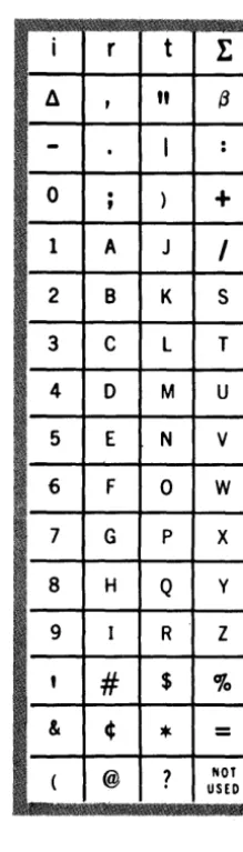
store data, constants or instructions. The 63 characters used to represent informa-tion are shown below.
i
rt
1:
II
,
"
13-
.
I
: 0.
,
)+
1 A J
I
2 B K S
3 C L T
4 0 M U
5 E N V
FIGURE 2· 18 6 F 0 W
CHARACTERS 7 G
P X
8 H Q y
9 I R Z
,
#
$%
& ¢
*
=
( @
?
NOTUSED
One cell can store one "wordH
, a word being any permutation ,:>f twelve characters.
The following are examples of words.
JOHN~J~JONES JUNE~I O~1926
0123~5678901 AOOIOOC00200
29
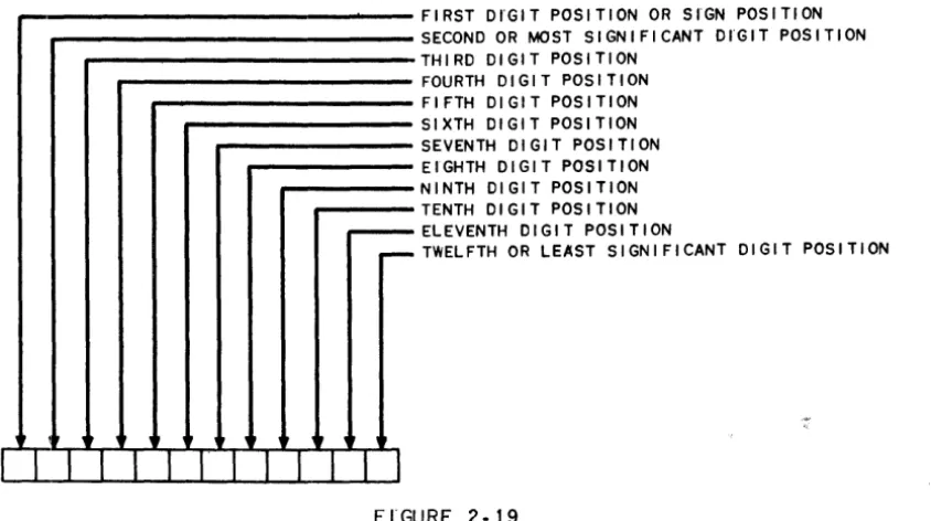
The positions of the characters in a word are named as follows.
~
,
r ,FIRST DI'GIT POSITION OR SrGN POSITION SECOND OR MOST SIGNIFICANT DrGIT POSITION THIRD DIGIT POSITION
FOURTH DIGIT POSITION FIFTH DIGIT POSITION SIXTH DIGIT POSITION SEVENTH DIGIT POSITION EIGHTH DIGIT POSITION NINTH DIGIT POSITION TENTH DIGIT POSITION ELEVENTH DIGIT POSITION
TWELFTH OR LEAST SIGNIFICANT DIGIT POSITION
I I I I I I
I' 1 1 1 1 II
FI'GURE 2·19
If a word represents an algebraic quantity, the sign of the quantity must be in the
sign position. A plus sign is represented by a zero; a minus sign, by a minus.
FIGURE 2·20
WORD AS A SIGNED QUANTITY
Once a word has been transferred to a cell, it remains in that cell until another word is transferred to take its place.
Figure 2-21 is a stylized version of the memory unit storing instructions, data and constants.
FI'GURE '2-2 t
THE CONTROL UNIT
Tlie code for an instruction is represented in SiX characters. Consequently, two instructions, called an instruction pair, are represented in one word.
FIGURE 2-22
PAIR
LEFT HAND INSTRUCT I ON
(I I
1
I
WORD
The function of the control unit is to select, in the proper sequence, each instruc-tion in the memory, interpret it and execute it. Instrucinstruc-tions are selected in pairs, one word, at a time. The left hand instruction (LHI) is executed, and then the right hand instruction (RHI). Thus, the control unit operates on a three stage cycle.
1. Select an instruction pair from the memory. 2. Execute the LHI.
3. Execute the RHI.
The selection of instruction pairs is performed in a sequential manner. That is, if the instruction pair just executed is in cell 0019, the next pair to be executed is in cell 0020.
31
Initially the control unit begins the sequential execution of instruction pairs with the pair in cell 0000. Thus, to have instructions executed in sequence, it is only necessary to represent the first instruction in the LHI of the word in cell 0000; the second in the RHI of the word in cell 0000; the third in the LBI of cell 0001; and so on.
CONTROL
FI'GURE 2·23
THE ARITHMETIC UNIT
LIFT HAND I . . TRUCTION
RIGHT HAND I "STRUCT I ON
INSTRUCT I ON INSTRUCTION INSTRUCTION INSTRUCTION INSTRUCTION INSTRUCTION
The arithmetic unit has characteristics In common with a desk calculator in that
it contains an adder to produce the sum or difference of two words, a multiplier the product, and a divider to produce their quotient. In addition, to enable the Central Computer to make logical decisions, the arithmetic unit contains a com-parator, which inspects two words to determine their equality or relative magnitude.
To operate on a word in the memory, the Central Computer must transfer the word
to the arithmetic unit. To provide storage for such words, the arithmetic unit
con-tains four registers named A, X, Land F. The arithmetic registers are identical to memory cells except that they are auxiliary to the memory. The registers serve the arithmetic unit in the same way as dials serve a calculator; each register
stor-ing either a word to be operated on or the result of an operation.
Figure 2-24 is a stylized version of a portion of the arithmetic unit.
ARITHMETIC
UNIT
FIGURE 2·24
FROM MEMORY
TO THE
q...--~I----4+---40--"" MEMORY
SI6UL
_ - . . TO
COHROL
UKIT
The memory, control and arithmetic units and their interrelations are shown here:
(The 60 word registers I and 0, used for input and output and the multiword
chapter
3
Introduction to Coding
The preparation of a problem for its solution by The Univac Data Automation Sys-tem is called programming. Programming is done in three steps.
1. Process Charting - The layout of the data processing system in terms of input, output and processing.
2. Logical Analysis - The analysis of the processing into a sequence of
tc small" logical steps.
3. Coding - The translation of the logical analysis into instructions.
PROCESS CHARTING
Figure 3-1 is a process chart.
In this manual all problems requiring logical analysis and coding are given in dis-cursive form. All the problems specify three things - input, processing and output and could be put in process chart form which is the usual basis for analysis and cod-ing.
35
UNIVAC®//
PROCESS
CHARTFIGURE 3· 1
CODING
L
UP DATE ON HAND AMOUNT
~
INPUT
...- PROCESSI NG
~OUTPUT
Computers usually perform a function in a series of operations. Each operation is executed under the influence of an instruction. An instruction specifies at least two things.
1. the operation to be performed. 2. the data to be operated on.
The data is usually specified in terms of the storage in which the data is to be found. For example, the data might be specified in terms of the address of the cell in which it is stored.
A computer might perform the function of adding two quantities together and record-ing the sum in three operations.
1. Select one quantity.
If one quantity is in cell 1880; the other, in 1881; and if the sum is to be stored in cell 1882; the instructions to cause the computer to do the above operations might be:
1. BRING 1880
2. ADD 1881
3. CLEAR 1882
where BRING, ADD and CLEAR are code for the operations to be done; and 1880, 1881 and 1882, the addresses of the cells in which the data is stored.
In the central computer of the lJnivac Data Automation System an instruction con-sists of six characters, named as follows.
FIRST SECOND THIRD FOURTH FIFTH
I.NSTRUCTION DIGITS
FIGURE 3.'2
SIXTH
The first and second instruction digits indicate what operation is to be performed; the third through sixth digits, the address of the word affected by the operation.
~
!
I
AT
lH
IS~ ~
____________
~____________
~;7WHAT TO DO .. TO •••• THE WORD ADDRESS
FIGURE 3.3
The instruction
.501880
tells the central computer to perform the operation indicated by n50" on the word in cell 1880.
ARITHMETIC INSTRUCTIONS - LIST A
An «fm" is used to symbolized the third through sixth instruction digits.
Paren-theses are used to symbolize C C the contents of". The symbol (m)
37
UNIVAC®II
means nthe contents of cell m". An t tr" IS used to symbolize nregister". The
symbol
rA
means Cf register A". An arrow is used to symbolize n is (are) transferred to". The
symbol
(m) ... A
means n(m) are transferred to rA".
To process data, the computer must read the data from tape and store it in the
memory. There are ins~ructions that, when executed, do the reading. These
lfi-structions will not be discussed at this time. Instead, reading data will be in-dicated by the words, "Read Data".
INSTRUCTION OPERATION MNEMONIC
BOrn (m)--...rA, rX Bring
Transfer (m) to rA and rX, or bring (m) to rA and rX.
INSTRUCTION OPERATION MNEMONIC
COm (rA) ... m; O--lll--rA Clear
Transfer (rA) to m. Transfer a word of zeros to rA, or clear rA.
One of the possible uses of these instructions is to transfer a word from one cell to another. If the word in cell 1880 is to be transferred to cell 1881, the sequence of instructions might be
B01880 C01881
INSTRlJCTION OPERATION MNEMONIC
HOm (rA) Ii m Hold
Transfer (rA) to m.
1881
rA
rX
B
o
1 8
1011\21311115161 7181 9101" /012131 11 IsI617Its\9\011\2\
FI GURE 3-4
INSTRUCTION
10m
8
1880
o
1881roI3"/
11\5\6\7\8\9\ 0 \1 \2 \31 rA \ 0 11115\617\8191 0II
12\3 111 \ rX8
8
1 ••••••••••••• 111 ••••
1.'.'
0I
0I
0I
0I
0 \ 0 \ 0I
0 \ 0 \ 0 \ 0 /0/ 10\1/2/3\11\5\6\7\8\9\0\11OPERATION
(rX)~m
Transfer (rX) to m.
1
1880
1881
rA
rX
One of the possible uses of these instructions is to duplicate the contents of a certain cell in several other cells. If the contents of cell 1880 are to be duplicated in cells 1881, 1882 and 1883, the instructions might be
801880 H01881 101882 C01883
or: B01880 101881
101882 101883
or: 601880 H01881
H01882 H01883
etc.
INSTRUCTION OPERATION MNEMONIC
AOm (m) ... rX; (rA) + (rX)---..rA Add
Add (rA) and (m), and transfer the sum to rA.
39
UNIVAC®IIB
8
1880
1881
I
Ai A I A I A I A/ A I A I A I A I A I A / A I/B/BIBIBIBI BIBIBIBIBIBlal
1882 I c I c I c I c I c I c I c I c I c I c I c I c I
1883 . I DID I DID I DID / DID I DID I DID I
rX
J
o
1
8
8
1880 [A I A I A I A I A I A I A I A I A I A I A I A I 1881 IA'lAIAIAIAIAIAIAIAIAIAIAI
1882 IAIAI AI AI AI AI AI AI AIAIAI A' . . . .
18e3 I DID I DID I DID I DID I DID I DID I
FIGURE 3.5
o
2
18BO
la(BIBIB/BIBIBIBlaIBIBIBI 1881
I c I c I c I c I c I c I c
I
c J c I c I c I c I 1882I DID I DID I DID I DID I DID I DID I 1883
I E
I
E I EI E I E I EI
E I E.I E I E I E I E I rA IFIFIFIFIFIFIF\FIFIFIFIFI rXH
I
A I A I A I AI A I A I A I A I A I A I A I A I 18eoIA IAIA I A IAI AI A IAIA I A IAI AI 1881
IclclClclclClclclclclclcl 1882
IDIDIDIDIDIDIDIDIDIDIDIDI t883
IAIAIAIAIAIAIAIAIAIAIAIAI rA
rX
C
0
I
1
8
I
8
I
3
I A I A I A / A I A I A I A I A I A I A I A I A I 18eo
I A I A I A I A I A I A I A I A I A I A I A I A I 1881
I A I A I A I A I A I A I A I A I A I A I A I A I 1882
• •
t
IAIAIAI AIAIAI AIAIAI AI A/AI le83The mnemonic is to add (rA) and (m). The computer executes the AOm instruction as follows. (m) are transferred to rX. (rA) and (rX) are added. The sum .is trans-ferred to rA.
To add the contents of cell 1880 to the contents of cell 1881 and store the sum in 1882, the sequence of instructions might be
B
1880
1881
rA
rX
c
o
1
B01880 A01881 C01882
8
8
I 0 II I 2/31 ~ l·s16171 8/ 9/ 0 /1 /
o
ADDER
o
1 8 8
2
1880 10 II 1213111IsI6\7/8\91 0 II I
1881 lo121al~ls161718191011121
1880
1881
\ 0 \3\ ~ \S\6\7\8191 0 II 1213\ 1882
I 0 I ~ I S/6/7/8/9/ 0 /1 /2/3 I ~ I rA
\ 0 lsi 6\ 7\8\9\ 0 /1 \2\al ~ lsi rX
[A
I
0
I
1
8 8
1
1881
1882
rA
rA
1882
@illIT£]IEI!D~I0_
• • • • • • • • • • • • • • •
-or
rA
rX I 0 1213/lIlsI6/718191 0 II 121
B01880 A01881 H01882
if it is desired to preserve the sum in rA.
41
FrGURE 3·6
UNIVAC®//
INSTRUCTION OPERATION
XOm (rA) + (rX)---..rA
Transfer the sum of (rA) and (rX) to rAe
When executing the XOm instruction the computer ignores m.
One of the possible uses of the XOm instruction is to add the same number to a sum more than once. Assuming that a quantity is in cell 1880, the sequence of instructions to build up three times the quantity might be
B01880 XOOOOO XOOOOO
I
BID
I
1
1
8
1
8
I
0
I
1880
rA
x
rX
ADDER
x
I
0\
0 \ 0 \ 0
o
FLGURE 3·7
o
101112131415161711J1910111 101213/4/516171819101112/
10 1 0 1 0 II 1210 101 0 I 0 II 1210·1
o o o
IA~O
rA
rX
rA
rX
o
INSTRUCTION OPERATION MNEMONIC
SOm -(m)~rX; (rA) + (rX)-...rA Subtract
Subtract (m) from (rA). Transfer the difference to rAe
The mnemonic is to subtract (m) from (rA). The computer executes the SOm in-struction as follows. Minus the (m) are transferred to rX. (rA) and (rX) are added. The sum is transferred to rA:
1880
rA
rX I A
I
B II 12131 q Ie I D II 121 31 q IADDER
s
o
1
I
81 8
o
FIGURE 3.8
loin I 0 1010 10/0/0/0/1/ S /0 I
SIGN CHANGER
1880
rA
rX
If the contents of a cell are negative, minus the contents would be positive.
INSTR UCTION OPERATION
50m (m)-...SCP
Print (m) on the Supervisory Control Printer (SCP).
1880
5
o
1
8 8
o
ALP H A X X BRA V 0
FI'GURE 3.9
43
UNIVAC®/1
INSTRUCTION OPERATION
90m
StopStop operation
In executing the 90m instruction, the computer ignores m.
ILLUSTRA TIVE EXAMPLE:
Reading the data stores the ON HAND quantity of a commodity in cell 1880, the ON ORDER quantity in cell 1881, and the EXPECTED REQUIREMENTS for the
next 60 days in cell 1882. Print (on hand) + (on order) - (required). (Data will
frequently be stored in memory starting at cell 1880 because of programming con-venience. Reasons for this will be described in a later chapter.)
LOGICAL ANALYSIS
1. Read the data.
2. Add the on order to the on hand. 3. Subtract the required from the sum. 4. Print the difference.
5. Stop.
CODING
0000 READ
}
Read the dataDATA
0001 B01880
}
Add the on order to the on handA01881
0002 S01882 Subtract the required from the sum
C01883
}
0003 501883 Print the difference
900000 Stop
The following is a description of the thinking that might have accompanied this coding. (The next new material begins on page 46.)
and moving sequentially through the instruction pairs following, the instruction pairs should be stored in logical sequence, starting in cell 0000. Furthermore,
since the computer executes the LHI of an instruction pair before the RHl, the first instruction of a pair to be executed should be coded as the LHI.
The .logical analysis shows that the first st~p is to read the data. This step is
shown by writing HRead Data" in cell 0000.
The next 'step in the analysis is to add the on order quantity to the on hand quantity. The computer will add two quantities if it is given an AOm instruction. But the AOm instruction adds those quantities stored in rA and m. The on hand and on order quantities are in cells 1880 and 1881. Before the quantities can be added together one must be stored in rA. To store a quantity in rA, the BOrn instruction can be used. To store the on hand quantity in rA the LHI in cell 0001 should be:
B01880
At the completion of the B01880 instruction the on hand quantity will be in rA. To add the on order quantity to (rA), the instruction needed is
A01881
which should be the RHI of cell 0001.
After the execution of the AOm instruction the