IJISET - International Journal of Innovative Science, Engineering & Technology, Vol. 2 Issue 12, December 2015. www.ijiset.com
ISSN 2348 – 7968
VLSI Architecture of a Clock-gating Turbo Encoder for
Wireless Sensor Network Applications
Anitha.VP 1
P
, Dr.T.MenakadeviP 2
P
1
P
Electronics and Communication Engineering, Adhiyamaan College of Engineering,
Hosur, Tamil Nadu, India.
P
2
P
Electronics and Communication Engineering, Adhiyamaan College of Engineering,
Hosur, Tamil Nadu, India.
Abstract
Wireless sensor network can be considered to be energy constrained wireless scenarios, since the sensors are operated for extended periods of time, while relying on batteries that are small, lightweight and inexpensive. Much architecture has been proposed for energy constrained wireless communication applications using look-up table. The conventional turbo decoder architecture requires high chip area and hence high power consumption. This motivated the proposed system to design the decoder architecture with high throughput, less decoding iteration and less memory requirement. Clock gating is a technique that can be used to control the power dissipated by clock net. The proposed work is implemented using clock gating technique in order to reduce the power consumption. The previous turbo decoder architectures uses optimal-log based algorithm which has the complexity about 75% and requires sequential operations hence leads to time and energy consumption. Whereas the proposed architecture uses the fundamental Add Compare Select(ACS) operation. Due to the parallel processing operation ACS blocks tend to have low processing steps, so that low transmission energy and less complexity about 71%. The proposed work implementation has a throughput of 1.03 Mb/s, memory requirement of 128.8 Kbps, the complexity is reduced by 4% and the power consumption is reduced by 32%.
Keywords: Lookup table architectures, Clock gating technique, Throughput, ACS block, Transmission energy.
1. Introduction
VLSI technology defined the edge of the ASIC business, which accelerated the push of powerful embedded systems in to adorable products. A Wireless Sensor Network is spatially distributed autonomous to monitor physical or environmental conditions in order to send their data through the network to a main location. But, designing the decoder on the receiver side encounters many challenges like algorithm complexity, large silicon area, high power consumption and low throughput. The proposed work is concentrated on designing the parallel turbo decoder which fits for the Wireless Sensor network applications.
Turbo codes are on the verge of finding their way in numerous cutting edge applications like cellular
communications and satellite communications. A turbo decoder is composed of modules that work in an iterative scheme. Some alternative algorithms exist for the algorithm incorporated in these decoder modules. Recent Application-Specific Integrated Circuit (ASIC) based decoder architectures have been designed [1] for achieving a high transmission throughput, rather than for low transmission energy. This addresses design and implementation aspects of parallel turbo decoders that reach the 326.4 Mb/s peak data-rate using multiple soft-input soft-output decoders that operate in parallel.
The Error-Control Coding (ECC) is implemented in Wireless Sensor Networks (WSN), to determine the energy efficiency of the specific ECC implementations in WSN are been proposed [2]. ECC provides coding gain, resulting in transmission energy savings, at the cost of added decoder power consumption but is not an error-control code, as there is no encoding.
C.Schlegel (2011) defined the physical layer (PHY) and Medium Access Control (MAC) sub layer specifications for less data rate wireless connectivity with fixed, portable, and moving devices with no battery or very limited battery consumption requirements. The energy consumption of Amplitude Shift Key (ASK) is (i.e.14.013 mJ) less than Offset Quadrature Phase Shift Key (OQPSK) (i.e. 15.401 mJ) but due to its high sensitivity to noise this modulation scheme is rejected and OQPSK is chosen[3].
A modified version of the BCJR algorithm, that has redesigned vigorously is also used [4]. There are several simplified versions of the Maximum A posteriori Probability (MAP) algorithm, namely the log-MAP and the max-log-MAP algorithms. But in this case power consumption is high and it is sensitive to signal that produces more noise. J.M.Mathana (2014) presents VLSI architecture for an efficient turbo decoder using sliding window method. The speed of the implemented architecture is improved by modifying the value of the branch metrics [5]. But this method occupies a large amount of chip area.
A low-complexity ACS (add compare and select) architecture is introduced in WSN decoder design. The entire decoder architecture is coded using Verilog HDL and it is synthesized using Xilinx EDA with Spartan 3E FPGA[6]. But this design is said to be
more complicated and requires more cost because of large usage of components.
A flexible and efficient VLSI architecture to solve the memory conflict problem for highly parallel turbo decoders targeting multi standard 3G or 4G wireless communication systems is been proposed [7].But this method achieves a high throughput only when the clock rate is high it doesn’t support for low clock rate.
Guido Masera (2013) proposes a VLSI decoding architecture for concatenated convolution codes. (i) the possibility to switch on-the-fly from the Universal Mobile Telecommunication System (UMTS) turbo decoder to the WiMax duo-binary turbo decoder with a limited resources (ii) the design of a parallel, collision free Wireless Max decoder architecture [8].But this method doesn’t achieve a better memory space, it uses a very large memory space.
This motivates the employment of the lookup table based algorithms in energy-constrained scenarios, since it approximates the optimal Log more closely than the Max-Log [9] and therefore does not suffer from the associated coding gain degradation. By this survey it is understandable that, no lookup table based ASICs have been specifically designed for the energy constrained scenarios.
Previous lookup table based turbo decoder designs were developed as a part of the drive for higher processing throughputs, although their throughputs have since been eclipsed by the Max-Log architectures. This opens the door for a new generation of LUT based ASICs that exchange processing throughput for energy efficiency.
Taking all these points in to account, the proposed work motivates to make the decoder architecture energy efficient. This work introduces the clock gating technique in decoder architecture. By using the clock gating technique the power consumed by the unused gates during the decoding process can be eliminated. The proposed work organizes as follows.
The conventional LUT based architecture is discussed in section 2. Section 3 deals with the proposed decoder architecture and its algorithm. Section 4 describes about the results and discussions of the work. Section 5 deals with the conclusion and future work.
2. Conventional Lookup Table Based
Architecture
The existing system design, consist of the Lookup table log based architecture into its most functional add compare select (ACS) operations and perform them using a novel low-complexity ACS unit. The proposed work also produces the simulation for energy efficiency, and power reduction [10].The Max-Log algorithm [9] appears to demonstrate itself to both
high-throughput scenarios, as well as to the above mentioned energy constrained scenarios. The low turbo decoder energy consumption is implied by Max-Log algorithm [10] which achieves low complexity.
The low-complexity is achieved at the cost of reducing the coding gain by 0.5 dB compared to the optimal Log algorithm increasing the required transmission energy by 10%.This disadvantage of the Max-Log outweighs that it is attractively low complexity, by optimizing the overall energy consumption of sensor nodes that are separated by long distance.
2.1 Turbo coding
2.1.1 Encoder Setup
A turbo encoder consists of a parallel linking of two relatively low constraint length convolution codes as depicted in figure 1. A pseudo random interleaver separates these two component codes (ENC1 and ENC2). The size of the interleaver determines the performance of the code, which is better for larger values of N. The turbo code operates as a block code transforming the input bits into output bits that are transmitted.
For every new input block, the encoder is said to start in a known initial state. In order to have an end state, some extra input bits, called tail bits are generated. Generally this is done only for ENC1. This method is extended and tail bits are added after the interleaver also, in order to force ENC2 in a known end state. This scheme is referred as full termination. Another option is to force both the encoders to its known end state is to use precursor bits as in. Both schemes reduce the throughput a little, but improve the decoding performance and allow the optimization of the decoder module.
2.1.2 Decoder Setup
A maximum of the turbo decoder would be prohibitively complex. The iterative decoding scheme is a clever solution for this problem. Both of the decoder modules (DEC1 and DEC2) produces an increasingly better correction term which is appropriately de-interleaved and used as a priori information by the next module. The other inputs of a decoding module are the log ratios of the received symbols,
FR – Forward Recursion
P-BR – Pre-Backward Recursion
BR – Backward Recursion
Fig. 1 Turbo encoder and decoder scheme.
2.1.3 Turbo codes
Turbo-like codes generally have a simple encoding scheme and a relatively complicated decoding scheme.
Fig. 2 The channel encoding and decoding system over a channel.
Turbo decoder architecture uses 3rd Generation Partnership Project (3GPP) and Universal Mobile Telecommunication System (UMTS) standard as an example to introduce the typical turbo coding schemes. This algorithm includes convolution code algorithm and the SISO decoding algorithm.
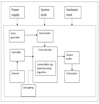
3. Proposed Clock gating Turbo decoder
Architecture
In the proposed system the lookup table log based architecture is designed with Clock gating technique which leads to reduction in power consumption and
energy consumption. The circuit is converted into digital hardware.
Fig. 3 Proposed system architecture.
The proposed system consists of a novel architecture suits for the energy-constrained scenarios, which avoids the wastage of energy in the conventional architecture. The min work is to redesign the timing of the conventional architecture in a manner that allows the components to be efficiently merged.
This produces an architecture comprising only a low number of low-complexity functional units, which are collectively capable of performing the entire algorithm. More wastage is avoided, since the critical paths of the functional units are naturally short and equally lengthened. This eliminates the requirement for additional hardware used for the purpose of managing.
3.1 LUT based algorithm using clock gating technique
There are two main advantages of inducing LUT based Log algorithm. Firstly, the original algorithm consists of many multiplication operations which lead to very complex circuits while implementing in hardware. Log algorithm avoids the multiplications by transforming the algorithm into the logarithmic domain, where multiplications become additions. Secondly, it values of soft decisions in the normal domain could have a very large dynamic range and theoretically unlimited, which leads to a large amount of memory space in practice. To transfer them to logarithmic domain reduces the dynamic range of the soft decisions and consequently all the internal variables in the algorithm. Hence significantly this approach reduces the memory requirement to implement the algorithm.
(a)
(b)
Fig. 4 (a) Conventional lookup table architecture (b) Timing of the sliding-window technique.
Notation ‘y’ is used to represent two bits namely systematic bits (‘a’) in the encoder including the termination bits (‘e’), which leads to
y = [a, e] (1)
and this can be used to represent the received un coded sequence LLRs in the decoder
{yn}^Ny (2)
where n=1 and
N represents the bits
The conventional architecture, which employs the sliding window technique Fig 4(b), to generate the LLR as the concatenation of equal length sub sequences. Each of these windows is generated separately, using a forward, a pre-backward and a backward recursion. These three different recursions are performed concurrently for three different windows.
A novel lookup table based architecture, which avoids the wastage of energy and allows its components to be efficiently merged, is proposed in this work. Furthermore, this approach naturally results in a low area and a high clock frequency that leads to low static energy consumption.
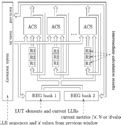
The proposed energy-efficient lookup table based architecture does not use a separate dedicated hardware for the three recursions instead this implements the entire algorithm using the ACS blocks in parallel, each of which performs one ACS operation per clock cycle.
The proposed architecture consists of a twin level register structure to minimize the main memory access operations which requires high level energy consumption. At the first register level, each ACS unit is paired with a set of general purpose registers R1, R2, and R3.
The general purpose registers are used to store intermediate results that are required by the same ACS unit in consecutive clock cycles. Hence the proposed turbo decoder architecture is said to have the least memory requirement and less energy consumption. Due to the parallel operation of the ACS block in the decoder architecture the design is said to be time constrained. The outputs of four ACS block is said to be considered for a single max operation in the turbo decoder.
Fig. 5 Energy-efficient lookup table architecture.
This allows the four ACS operation to be performed in four consecutive clock cycles using a single ACS unit, as the second register level comprises REG bank 1 and REG bank 2 as shown in Fig.5 which are used to temporarily store the table variables between consecutive values of the bit index during the recursions decoding processes. The REG bank 1 comprises registers for the priori LLRs and dummy registers for the required LUT constants. Meanwhile, the sets of or metrics are stored in REG bank 2.
The main memory stores all the required priori LLR sequences and extrinsic LLR sequences during the decoding process and also the state metrics that comes from the previous window, which facilitates the processing of the entire algorithm. Since the proposed architecture is implemented with a fully parallel
arrangement of an arbitrary number of ACS units this may be readily applied to any log based decoder, regardless of the specific convolution encoder parameters employed.
Clock gating is a technique which is used to control power dissipated by clock input. The disadvantage of the clock gating is that the enable signal is generated by user software. If the protocol can generate the enable signal automatically by itself, the user software will be no need. Any application core can be modeled as a Finite State Machine (FSM) which includes several states like Idle, Ready, Run and so on. The state and the transition of the design will be mapped to the sequential circuit and the combinational circuit respectively.
When the core finishes its work, the bit enters the idle state (IS) and stays idle until it accepts another request from the system bus. Each of those states are called except IS working state (WS). All states in an IP core are classified to two classes. When an IP core stays in the IS for some cycles, it does not need the clock.
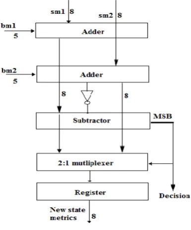
3.2 ACS Unit
The goal of the add-compare-select unit is to add the branch metric for an edge in to its path metric of the present trellis state. This is done in order to create a new path metric for a next state in the next trellis stage. This metric is then compared to the computed path metric from the competitive path to determine the survivor for the next state. The ACS operation must be performed for at most Nmax present state path metrics for each trellis stage.
Fig. 6 ACS unit.
The novel low-gate-count ACS unit performs one ACS operation per clock cycle. The control signals to the ACS units are provided by the operational Code, which can be used to perform the functions of the block.
Note that the operation code approximates the absolute difference between two operands. Its result is said to be equivalent. The second complement operand representation employs the fraction bits this is equivalent to decrementing the binary representation and subtraction.
Note that a simpler ACS unit implementation is facilitated by this inaccuracy, which can be trivially canceled out during the calculation. More specifically, a calculation can be performed with the following four operations, which store intermediate results in the registers.
4. Results and Discussions
At the encoder side the 8-bit data is been generated with the help of Linear Feedback Shift Register, the obtained output is encrypted and finally sent through the communication channel. For the purpose of encryption we use a constant 8-bit code to do the process of “AND”ing with the original bit.
In this section the output waveform for 8-bit input data generation, counter and the clock divider circuit is been produced which can be further developed to an encoder of turbo code. The 8-bit input is generated with the help of linear feedback shift register (LFSR), which involves clock, reset and enable as inputs that produces 8-bit random output for the purpose of encryption. The RTL schematic and the output waveform of the LFSR are discussed in figure 7 and 8.
Fig. 7 RTL schematic of generating random input.
Fig. 8 Waveform of generating random input.
In the proposed architecture the clock divider is used to distribute the clock signal to each and every block equally. By implementing this the waiting time of
the block for the clock signal can be reduced. This includes clock and reset as input and the clock_divided
output signal. The RTL schematic (i.e) the internal circuit of the clock divider is discussed in the following figure 9 and figures 10 deals with the output waveform.
Fig. 9 RTL schematic of clock divider.
Fig. 10 Waveform of clock divider.
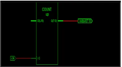
The input bits generated as per the above mentioned technique will be sequential in order to send the input randomly. The counter counts the random 8-bit input (i.e) 28 = 256 combinations randomly and sends to the purpose of encryption at the encoder side and then sent through the communication channel to the decoding operation. The proposed architecture is implemented at the decoder side and carries out the further decoding operation. The following figure 11 and 12 deals with the RTL schematic and waveform of the counter.
Fig. 11 RTL schematic of counter.
Fig.
Fig 12 Waveform of counter.
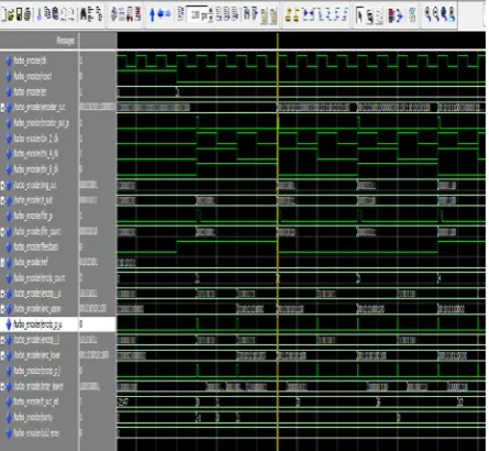
The turbo-encoder that includes the above designed block such as 8-bit input data generation, clock divider and counter for the process of encoding. In this design the input bits are encrypted using XOR operation. Further the code is sent through the channel for the turbo decoder. This turbo encoder uses an interleaver for error detection and correction purpose. The final output waveform and the RTL schematic and the waveform of the proposed turbo encoder are given in the figure 13 and 14. The parameters of the proposed encoder is discussed in table 1.
Fig. 13 RTL schematic of the turbo encoder.
Fig. 14 Output waveform of turbo encoder.
Table 1: Calculated parameters of the proposed turbo-encoder.
At the decoder side the ACS unit is the main block in the proposed architecture. This generates the Most Significant Bit which is considered to be the output of the bits stored from the main registers of the decoder. The RTL schematic and the output waveform of the ACS block are given in figure 15 and 16. The ACS block is used in parallel such that the decoding operation is said to be faster than the conventional encoder. The operations taken place in the decoder are:
1. Addition 2. Subtraction 3. max*
Fig. 15 RTL schematic of ACS block.
Fig. 16 Waveform of ACS block.
The max* operation in the decoder is done by using the output of 4 ACS blocks. And finally the bits will be decrypted using the code word stored in the main memory and gives the original input bit. The comparison of the resulting parameters is discussed in table2.
Table 2: Comparison of resulting parameters
The parameters of the proposed architecture is compared with the other decoder architectures and analyzed that the proposed architecture uses less memory space and increased throughput. But the throughput is less when comparing to the Max-log and UTMS architecture this is because the number of decoding iterations is less when compared to the proposed architecture.
5. Conclusion
In the present scenario wireless technologies play a vital role. The turbo decoder carries out some major applications such as satellite communication, mobile telephony, internet etc. Realization of turbo decoder algorithm in hardware encounters lots of challenges such as algorithm complexity, large silicon area, high power consumption and low throughput. Taking these drawbacks in to account the proposed lookup table log based architecture is designed in such a
way that it supports high data rate, high throughput, high speed and reduced number of decoding iterations. This can adopt look-up table log based architecture technique to reduce the hardware complexity by 4% and power consumption by 32%. This work implementation has the throughput of 1.03 Mb/s and memory requirement of 128.8 Kbits which makes the decoder fit for the present wireless network applications. In this paper the results up to the turbo encoder design is produced and the techniques are discussed.
5.1 Future work
In synchronous digital circuits the clock net is responsible for significant part of power dissipation Clock gating reduces the unwanted switching on the parts of clock net by disabling the clock. Clock signals is said to be a great source of power dissipation because of high frequency and load. Clock signals do not perform any computation operation but mainly used for synchronization. Hence these signals are not carrying any information. So, by using clock gating one can save power by reducing unused clock activities inside the gated module. A review of some existing techniques available for clock gating will be presented. Also a new technique that provides more immunity to the existing problems in available techniques will be discussed in the decoder design.
References
[1] Christoph Studer, Christian Benkeser , Sandro Belfanti, and Qiuting (2011) ‘Design and Implementation of a Parallel Turbo-Decoder ASIC for 3GPP-LTE’, IEEE journal of solid-state circuits.
[2] T.Wark, R.jurdak (Nov 2010) “Error Control Coding in Low-Power Wireless Sensor Networks: When is ECC Energy-Efficient”Proc. IEEE, vol98, pp. 1903-1917.
[3] C.Schlegel, and K.Iniewski (2011), “Energy Efficiency of the IEEE 802.15.4 Standard in Wireless Sensor Networks: Modeling and Improvement Perspectives”IEEE 802.15.4 standard.
[4] E. Boutillon, C. Douillard, and G. Montorsi (Jun 2007) ‘Iterative decoding of concatenated convolutional codes: Implementation issues’, Proc. IEEE, vol. 95, no. 6, pp. 1201–1227.
[5] S.Badrinarayanan, J.M.Mathana and R.Rani Hemamalini Karthik (Feb 2014) ‘Efficient VLSI architecture of SISO based Turbo decoder for wireless applications’, International Journal of Advanced Research in Electrical, Electronics and Instrumentation Engineering. Vol. 3, Issue 2.
[6] Dr.J.M.Mathana, S.Gunasekar, S.Jagadish and R.Karthik (Apr 2014) ‘VLSI Architecture of High
Performance Turbo Decoder for Wireless Sensor Networks’, International Journal of Advanced Research in Electrical, Electronics and Instrumentation Engineering Vol. 3, Issue 4.
[7] Guohui Wang, HaoShen, YangSun, Joseph R. Cavallaro, Aida Vosoughi, and Yuanbin Guo (May 2014) ‘Parallel Interleaver Design for a High Throughput HSPA /LTE Multi-Standard Turbo Decoder’, IEEE transactions on circuits and systems.vol. 61, no. 5.
[8] Maurizio Martina, Mario Nicola and Guido Masera (2013) ‘A Flexible UMTS-WiMax Turbo Decoder Architecture’, IEEE transactions on circuits and systems.vol. 55 n. 4, pp.369-373. - ISSN 1549-7747.
[9] Z. He, P. Fortier, and S. Roy (Oct 2006) ‘Highly-parallel decoding architectures for convolutional turbo codes’, IEEE Trans. Very Large Scale Integr. (VLSI) Syst., vol. 14, no. 10, pp. 1063–8210.
[10] Liang Li, Robert G. Maunder, Bashir M. Al-Hashimi and Lajos Hanzo (Jan 2013) ‘A Low-Complexity Turbo Decoder Architecture for Energy-Efficient Wireless Sensor Networks’, IEEE transactions on very large scale integration (vlsi) systems, vol. 21, no. 1.
[11] Hesham El Gamal and A. Roger Hammons (Feb 2001) ‘Analyzing the Turbo Decoder Using the Gaussian Approximation’, IEEE transactions on information theory, vol. 47, no. 2.
[12] I.F.Akyildiz, W.Su,Y. Sankarasubramani, and E. Cayirci (2008) ‘Wireless sensor networks: A survey’, Comput. Netw.: Int. J. Comput. Telecommun. Netw., vol. 52, pp. 292–422.
[13] Jagdish D. Kene1 and Dr. Kishor D. Kulat (July 2013) ‘Iterative Decoding Termination Schemes for Turbo Code Performance Optimization In Mobile Wi-Max Environment’, International Journal of Computer Science Issues, Vol. 10, Issue 4, No 1, ISSN : 1694-0784.
[14] L. Hanzo, J. P. Woodard, and P. Robertson (Jun 2007) ‘Turbo decoding and detection for wireless applications’, Proc. IEEE, vol. 95, no. 6, pp. 1178–1200.
[15] L. Hanzo, T. H. Liew, B. L. Yeap, R. Tee, and S. X. Nang (2011) ‘Turbo Coding, Turbo Equalisation and Space-Time Coding’, New York:Wiley.
[16] L. Li, R. G. Maunder, B. M. Al-Hashimi, and L. Hanzo (2010) ‘An energy-efficient error correction scheme for IEEE 802.15.4 wireless sensor networks’, Trans. Circuits Syst. II, vol. 57, no. 3, pp. 233–237.
[17] L. Li, R. G. Maunder, B. M. Al-Hashimi, and L. Hanzo (2010) ‘Design of fixed-point processing based
turbo codes using extrinsic information transfer charts’, in Proc. IEEE Veh. Technol. Conf, pp. 1 – 5.
[18] P. Robertson, E. Villebrun, and P. Hoeher (1995) ‘A comparison of optimal and sub-optimal MAP decoding algorithms operating in the log domain’, in Proc. IEEE Int. Conf. Communication, pp. 1009–1013.
[19] P. Robertson, P. Hoeher, and E. Villebrun (1997) ‘Optimal and sub-optimal maximum a posteriori algorithms suitable for turbo decoding’, Euro. Trans. Telecommunication, vol. 8, no. 2, pp. 119–125.
[20] S.-G. Lee, C.-H.Wang, andW.-H. Sheen (2010) ‘Architecture design of QPP interleaver for parallel turbo decoding’ in Proc. IEEE Veh. Technol. Conf., 2010, pp. 1–5.
[21] Varun Gautam (June 2013) ‘A Concept Paper on VLSI Implementation of Turbo Decoders’, International Journal of Electronics & Communication Technology Vol. 4, Issue Spl - 3, ISSN : 2230-7109.
[22] W.-P. Ang and H. K. Garg (2001) ‘A new iterative channel estimator for the log-MAP & max-log-MAP turbo decoder in Rayleigh fading channel’, in Proc. Global Telecommun. Conf, vol. 6, pp. 3252–3256.
[23] Y. Sun and J. R. Cavallaro (2010) ‘Efficient hardware implementation of a highly-parallel 3GPP LTE, LTE-advance turbo decoder’, Integr., VLSI J., vol. 44, no. 1, pp. 1–11.
[24] Y. Zhang and K. K. Parhi (2006) ‘High-throughput radix-4 logMAP turbo decoder architecture’, in Proc. Asilomar Conf. Signals, Syst., Comput, pp. 1711–1715.
[25] A. J. Viterbi (1998) ‘An intuitive justification and a simplified implementation of the MAP decoder for convolutional codes’, IEEE J. Sel. Areas in Communication., vol. 16, no. 2, pp. 162–264.
[26] Alexander Worm, Heiko Michel and Norbert When ‘Implementation Aspects of Turbo-Decoders for Future Radio Applications’, University of Kaiserslautern Institute of Microelectronic Systems Kaiserslautern, Germany.
[27] C. Benkeser, A. Burg, T. Cupaiuolo, and Q. Huang (Jan 2009) ‘Design and optimization of an HSDPA turbo decoder ASIC’, IEEE J. Solid-State Circuits, vol. 44, no. 1, pp. 98–106,
[28] C. Berrou, A. Glavieux, and P. Thitimajshima (1993) ‘Near Shannon limit error correcting coding and decoding: Turbo codes’, IEEE Int. Conf. Communication pp. 1064–1070.
[29] C. Schurgers, F. Catthoor, and M. Engels (Feb 2001) ‘Memory optimization of MAP turbo decoder algorithms’, IEEE Trans. Very Large Scale Integr. (VLSI) Syst., vol. 9, no. 2, pp. 305–312.
[30] C. Studer, C. Benkeser, S. Belfanti, and Q. Huang (2011) ‘Design and implementation of a parallel turbo-decoder ASIC for 3GPP-LTE’, IEEE J. Solid-State Circuits, vol. 46, pp. 8–17.
[31] C. Wong, Y. Lee, and H. Chang (2009) ‘A 188-size 2.1 mm reconfigurable turbo decoder chip with parallel architecture for 3GPP LTE system’, in Proc. Symp. VLSI Circuits, pp. 288–289.
[32] C.M.Wu, M. D. Shieh, C. H.Wu,Y.T.Hwang, and J.H.Chen (Apr 2005) ‘VLSI architectural design tradeoffs for sliding-window log-MAP decoders’, IEEE Trans. Very Large Scale Integr. (VLSI) Syst., vol. 13, no. 4, pp. 439–447.
[33] F.-M. Li, C.-H. Lin, and A.-Y. Wu (Oct 2008) ‘Unified convolutional/turbo decoder design using tile-based timing analysis of VA/MAP kernel’, IEEE Trans. Very Large Scale Integr. (VLSI) Syst., vol. 16, no. 10, pp. 1063–8210.
[34] G. Barrenetxea, F. Ingelres, G. Schaefer, and M. Vetterli (2008) ‘Wireless sensor networks for environmental monitoring: The Sensorscope experience’, in Proc. IEEE Int. Zurich Seminar Commun, pp.98–101.
[35] G. Masera, M. Mazza, G. Piccinini, F. Viglione, and M. Zamboni (Mar. 2002) ‘Architectural strategies for low-power VLSI turbo decoders’, IEEE Trans. Very Large Scale Integr. (VLSI) Syst., vol. 10, no. 3, pp. 279– 285.