INSTALLATION
MANUAL
Package
2
Copyright 0 1995 Fujitsu Business Communication Systems All rights reserved.
Fujitsu Business Communication Systems shall not be liable for any commercial losses, loss of revenues or profits, loss of goodwill, inconvenience, or exemplary, special, incidental, indirect or
consequential damages whatsoever, or claims of third parties, regardless of the form of any claim
that may result from the use of this practice. I
Chapter
Title
Page
1 INTRODUCTION . . . l-1 INTRODUCTION . . . . l-l . . ORGANIZATION . . . .._... l-l REFERENCE DOCUMENTATION . . . l-2
Fujitsu Documentation . . . l-2 Industry Standards . . . l-3 GENERAL INFORMATION . . . l-3
SYSTEM CONSTRUCTION ... 2-1 CABINET CONFIGURATION.. ... 2-l
Basic Cabinet.. ... 2-l Expansion Cabinets ... 2-l Wall Bracket.. ... 2-l HARDWARE CONFIGURATION.. ... 2-3
Power Units.. ... 2-3 Floppy Disk Drive.. ... 2-3 CIRCUIT CARDS ... 2-5 Common Control Cards ... 2-5 Interface Cards.. ... 2-5 SYSTEM SPECIFICATIONS.. ... 2-5 SOFTWARE ... 2-6 MAXIMUM CAPACITIES.. ... 2-7
3
4
PREPARATIONS ... 3-l LIST OF MATERIALS.. ... 3-l MATERIALS NEEDED ... 3-l TOOLS ... 3-l INSTALLATION SITE REQUIREMENTS.. ... 3-3 SPECIAL INSTALLATION INSTRUCTIONS.. ... 3-4 WALL LAYOUT ... 3-4 POWER REQUIREMENTS ... 3-5 HEAT LOADING.. ... 3-5 GROUNDING REQUIREMENTS ... 3-5
Chapter
Title
Page
POWER BRACKETS ... 4-9 AC Cord ... 4-9 DC Power Cables.. ... 4-9 INSTALLING EXPANSION CABINETS.. ... 4-10 Installing the First Expansion Cabinet.. ... 4-10 Installing the Second Expansion Cabinet.. ... 4-l 1 Installing the Third Expansion Cabinet.. ... 4-12 INSTALLING THE SFDC.. ... 4-14 Installing the Floppy Disk Drive.. ... 4-15 POWER FAIL TRANSFER ... 4-16 Installing the ACPD or DCPD.. ... 4-17 Supplemental 24V Power Supply.. ... 4-l 8 CIRCUIT CARD INSTALLATION ... 5-1 GENERAL ... 5-l COMMON CONTROL CARDS.. ... 5-l INTERFACE CARDS.. ... 5-l LINE/TRUNK CARDS.. ... 5-2
Chapter
6 TERMINAL AND LINE CONNECTION ... 6-1 - PIN ASSIGNMENT OF MDF TERMINAL.. ... 6-l CROSS CONNECTION. ... 6-l METHOD OF WIRING ... ... ... 6-l ATTENDANT CONSOLE.. ... 6-l 0 DATA INTERFACE UNIT.. ... 6-10 WALL MOUNTING PROCEDURE FOR PROPRIETARY TELEPHONE.. ... 6-l 1 DATA TERMINAL ADAPTER (DTA) ... 6-15 DIGITAL STATION.. ... ... 6-18 DSS 30 ... ... 6-l 8
9
10
MAIN DISTRIBUTION FRAME ... 7-l ROUTING THE MDF CABLES.. ... 7-l
SYSTEM START-UP ... 8-I SYSTEM START.. ... 8-l DEFAULT DATA.. ... 8-l INITIAL PROGRAM LOADING.. ... 8-l START-UP PROCEDURE.. ... 8-3 IPL AFTER ODDB LOADING HAS BEEN STORED ON DISK.. ... 8-3
BAlTERY BACK-UP ... 9-I GENERAL ... 9-l HARDWARE.. ... 9-l Cabinet Hardware ... 9-l Battery Plant.. ... 9-l Battery Sizing ... 9-3
PERIPHERAL EQUIPMENT ... IO-I STATION MESSAGE DETAIL RECORDING (SMDR) PRINTER.. ... 10-l XON/XOFF Flow Control Option.. ... 10-l Power On/off Option.. ... 1 O-2 REQUIREMENTS FOR CABLE ... 10-2
DTE Mode Printer ... 1 o-2 DCE Mode Printer ... ... 10-2 RS-232C PORTS IN THE BASIC CABINET.. ... 104 SMDR INSTALLATION ... 1 O-5 SMDR SCREENING.. ... 1 O-5 SMDR FORMAT.. ... 10-6
Chapter
Title
Page
HOTEL/MOTEL PRINTER.. ... . ... 1 O-1 0 XONIXOFF Option ... 10-I 1 Power On/Off Option ... 10-I 1 CABLE REQUIREMENTS ... 1 O-l 2 Hotel/Motel Printer Cable Connection ... 10-12 Hotel/Motel Printer Installation ... ... 10-13 HOTEL/MOTEL PRINTER SCREENING.. ... ... . ... 10-13 HOTEL/MOTEL PRINT OUT FORMAT.. ... IO-1 3 RESPONSE PROCEDURES FOR MALFUNCTIONS ... 10-I 8 Paper End ... lo-18 Printer with XONIXOFF Option ... lo-18 Printer with Line Disconnect Option ... 10-19 Printer without Paper End Alerting Function ... 1 O-l 9 OTHER PROBLEMS.. ... . . . ... 10-19 ACD CALLS WAITING INDICATOR.. ... ... 10-19 Operational Checks ... 1 O-20 DIAGNOSIS.. ... lo-22 MUSIC SOURCE EQUIPMENT. ... 1 o-22 DICTATION MACHINE.. ... lo-22 EXTERNAL ALARM UNIT.. ... . . . . ... 1 o-22 APPLICATION PROCESSOR APPLIQUE.. ... 1 O-22
Chapter
Title
Page
12 WORK COMPLETION CHECK . . . 12-1 GENERAL . . . . 12-1 . Initial Setting of Real-Time Clock . . . . .._..._..._..._... 12-l Interface Card . . . . . . 12-1 . Extension-to-Extension and Attendant-to-Extension Verification . . . .._.. 12-1 CO Trunk Verification _ _ . . . 12-2 Tie Trunk Verification . . . 12-3 Data Terminal-to-Data Terminal Verification. . . ..~... 12-4 SYSTEM DATA VERIFICATION . . . 12-4 13
Appendix
A
FINAL INSTALLATION ... 13-1 DRESS UP . . ... 13-l Installation Check List (Cabinet) ... 13-1 Cabinet Covers ... ... 13-l Housekeeping.. ... 13-1
APPENDIXES
Title
Page
SPARE/OPTIONAL PARTS ... A-l PARTS NEEDED.. ... ... A-3
-
Table
2-l 2-2 3-l 3-2 3-3 5-1 5-2 5-3 5-4 5-5 5-6 5-7 5-8 5-9 5-10 5-l 1 5-12 5-13 5-14 5-15 6-l 6-2 7-1 7-12 8-1 8-2 9-1 9-2 9-3 9-4 IO-1 1 o-2 1 o-3 IO-4 1 o-5 11-l II-2 11-3 11-4 11-5 11-6 11-7 11-8LIST OF TABLES
Title
Page
Figure
2-l 2-2 2-3 3-l 3-2 4-1 4-2 4-3 4-4 4-5 4-6 4-7 4-8 4-9 4-l 0 4-l 1 4-12 4-13 4-14 4-l 5 4-16 5-l 5-2 5-3 5-4 5-5 5-6 5-7 5-8 5-9 5-l 0 5-l 1 5-12 5-13 6-l 6-2 6-3 6-4 6-5 6-6 6-7 6-8 6-9 6-10 6-l 1 6-12 6-13 6-14LIST OF ILLUSTRATIONS
Title
Page
Series 3 Cabinet.. ... ... . ... 2-l Four Cabinet Configurations.. ... 2-2 Series 3 Cabinet internal View ... ... 2-4 Unpacking the Cabinet ... 3-2 Series 3 Wall Arrangements.. ... 3-4 Wall Bracket Detail ... ... 4-2 One Piece Front Cover.. ... ... 4-3 Three-Piece Front Cover. ... 4-4 Access Port Covers.. ... 4-5 Bottom Cover Plate ... 4-5 Cabinet Installation ... 4-6 Power Distribution Unit, -48 VDC and RGMW Installed ... 4-7 Power and Ground Connections ... 4-8 DC Cable and G Ground Installation ... 4-9 Ground Cable, Address Extension Cable.. ... 4-l 1 Extended Cable Installation.. ... 4-l 3 Mounting the SFDC.. ... 4-14 Floppy Disk Drive Installation ... 4-l 5 Power Fail Transfer Card Installation ... 4-16 ACPD/DCPD Installation ... 4-l 7 24V Supplemental Power Supply Installation ... 4-l 8 Front View of the CPU Cards ... 5-4 4SLE Card Switch Positions.. ... 5-9 8BWC Card Jumper Configuration ... 5-l 0 2TE4 Card Jumper Configuration.. ... 5-12 4TE4 Card Jumper Configuration.. ... 5-l 3
Power Fail Transfer Card ... 5-14 6DID Card Jumper Configuration ... 5-l 5
Figure
7-l 7-2 7-3 7-4 9-l 9-2 1 o-1 1 o-2 1 o-3 10-4 10-5 10-6 1 o-7 1 O-8 1 o-9 10-10 10-11 10-12 10-13 10-14 10-15 lo-16 10-17 lo-18 10-19 1 O-20 1 o-21 1 o-22 1 O-23 11-l 11-2 11-3 12-1 12-2 12-3 12-4LIST OF ILLUSTRATIONS
(Cont’d)
Title
Page
INTRODUCTION This document contains information for the installation of Series 3 system hardware. This document assumes that the user is familiar with the operating principles of telecommunications systems and possesses the skills required for installing, configuring, and validating those systems.
ORGANIZATION The organization of this manual is as follows:
Chapter 1, Introduction: Describes the purpose and organization of the manual. Includes a list of Reference Documents.
Chapter 2, System Construction: Describes the physical characteristics and operation principals of the Series 3 system. Chapter 3, Preparations: Describes site requirements, unpacking instructions, and hardware inspection and handling instructions. Chapter 4, Cabinet Installation: Describes bracket and cabinet mounting, power unit installation, floppy disk drive installation, and inter-cabinet cables.
Chapter 5, Circuit Card Installation: Describes card mounting locations and inter-card connections.
Chapter 6, Terminal and Line Connection: Describes installation terminal equipment, including proprietary telephones, the Attendant Console, and other devices.
Chapter 7, Main Distribution Frame: Describes MDF cable connections, I/O connectors, Attendant Console wiring, T-l and 23PT cabling.
Chapter 8, System Start-Up: Describes system power-up, IPL, power-down, and data save procedures.
Chapter 9, Battery Back-Up: Describes sizing and installation of battery back-up equipment.
Chapter 10, Peripheral Equipment: Describes the installation of peripheral equipment.
Chapter 11, Property Management System Interface (PMSI): Describes the installation of PMSI equipment.
Chapter 12, Work Completion Check: Describes precutover testing to verify system operation after installation.
REFERENCE DOCUMENTATION
The following is a list of available documents:
Fujitsu Documentation System Description/Features (Section 123-001-002). Describes . in detail all of the features available in the system.
Applications Manual (Section 123-015-002). Used to assist in the installation, programming, and maintenance of the system.
Attendant Console User Guide (Section 123-040-002). Describes basic attendant console operating instructions.
Digital Station User Guide (Section 123-050-002). Describes Digital Station operating instructions.
CT-10120130 User Guide (Section 123-052-002). Describes CT-lo, CT-20, and CT-30 telephone operating instructions.
Single Line Telephone User Guide (Section 123-063-002). Describes single line telephone operating instructions.
Maintenance Manual (Section 123-060-002). Provides complete instructions for maintaining the Series 3 system.
Data Base Manual (Section 123-080-002). Provides information necessary to interface with the system and implementation procedures for each command.
Site Log Manual (Section 123-200-002). Provides configuration forms used for entering data base information.
It is recommended that pre-cutover tests be performed. This testing information is located in the Maintenance Manual and the Data Base. A brief test is also recommended to assure telephone operation. Such tests may require referencing the System Description/Features and User Guides.
Industry Standards The following additional documents may be helpful when installing the Series 3 system:
EIA Standard RS232C Interface Between Data Terminal Equipment and Data Communications Equipment Employing Serial Binary Data Interchange.
EIA RS-464 “Private Branch Exchange Switching Equipment for Voiceband Applications.”
EIA RS-464-1 “PBX Switching Equipment for Voiceband Applications, Addendum Number 1 .‘I
EIA PN-1429 “Proposal Addition” to RS-464.
EIA RS-478 “Multi-Line Key Telephone Systems (KTS) for Voiceband Applications.”
GENERAL INFORMATION l The Series 3 meets FCC Rules and Regulations, Part 68, and
Part 15Class A. . FCC Registration:
- Key System: BJ885Z-60084-KF-E - PBX System: BJ8USA-75355-PF-E
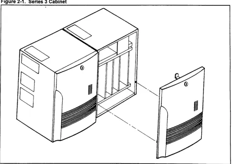
CABINET CONFIGURATION The Series 3 system is made up of one to four wall mounted cabinets. A two cabinet Series 3 system is shown in Figure 2-l. Figure 2-2 shows an exterior view of Series 3 four cabinet configurations; a basic cabinet and three expansion cabinets.
The Series 3 consists of the following hardware components:
Basic Cabinet The basic cabinet, referred to as cabinet zero, houses one of the power distribution boxes (ACPD or DCPD), the common control card (SC2P2B / SC2P2E or SC4P2B / SC4P2E), and various line and trunk cards
Expansion Cabinets The expansion cabinets are physically the same as the basic cabinet. Each expansion cabinet is equipped with a Main Power Supply Unit (MPSU). The third cabinet, in three and four cabinet systems, contains the SSDEC (switching expansion) card and a power distribution box (ACPDIDCPD).
Wall Bracket The bracket is mounted on the wall, and the cabinet is then secured to the bracket. The Series 3 system require a minimum of 12 inches clearance above and below each cabinet.
Fiaure 2-2. Four Cabinet Confiaurations
BASIC EXTENSION EXTENSION EXTENSION SERIES 3 CABINET MOUNTING
1 2 3 CONFIGURATIONS
NOTE: There must be a minimum of 12 inches clearance above and below all cabinets.
I I
BASIC EXTENSION EXTENSION EXTENSION
1 2 3
I I
T
OR 12”TO24”
EXTENSION EXTENSION EXTENSION
2 3 BASIC 1
I I
BASIC EXTENSION 1 t UPTO24” + EXTENSION 2 EXTENSION 3
HARDWARE CONFIGURATION
Power Units l ACPDIDCPD: The power distribution unit is the primary power
input to the Series 3 system. It is available in two versions: the ACPD for AC only operation; and the DCPD for AC with battery back up operation. Installed in the basic and second expansion cabinets.
. MPSU: The Main Power Supply Unit (MPSU) provides +/- 5VDC and -24VDC power for each cabinet. Each cabinet includes its own MPSU. Refer to Table 2-l.
. RGMW: The Ring Generator supplies 20Hz ring voltage and DC message waiting voltage for single line phones. One RGMW mounted in cabinet zero supplies ring voltage and message waiting power for cabinets zero and one. One RGMW in cabinet two supplies cabinets two and three. The RGMW is never installed in cabinets one or three.
. 48V PS: The -48V PS supplies -48 volts for 4SLE, 6DID and 4TE4 cards and for recharging the back-up batteries. The cabinets are connected by a power bus. When two or more 48V PS units are installed in a system, all units load share equally. Refer to Figure 2-3. Each 48V PS has a capacity of 3.0 Amps (A). The 6DID and 4TE4 cards draw an average of 0.3 A each. Any surplus current capacity can be used to charge external back up batteries. Refer to Chapter 9 for battery back up information, and to Table 2-l below.
. 24V PS: This power supply is mounted beneath the card shelf and has no switches. There is a green LED on the front edge.
Floppy Disk Drive The optional floppy disk drive stores the customer data base.
Table 2-1. Power Supply Front Panel Indicators, Switch, and Fuse Labels
POWER SUPPLY LABEL
OPE
uv
FUNCTION MPSU is operating correctly.
Under Voltage, the output of the MPSU is under the specifications.
MPSU
INT
Momentary loss of AC input power. An interruption longer than 10 ms, but less than one second. Must be manually reset. INT is disabled if battery back-up is installed.
-48V PS
24V PS
RES FUSE
OPE SYNC (none)
Reset switch for INT indicator.
48 volts output fuse. The -48 volts for 6DID and 4TE4 cards. -48V PS is operating correctly.
LA J
MPSU
63
r :
Tir :
Tr 4
i
lr :
Tr-m
:
L
T :
nnr
ir
L L L L L
: : : : i
1
4 5 6 7 8 9 10
CIRCUIT CARDS
Common Control Cards
Interface Cards
SYSTEM SPECIFICATIONS
l SCPNZM: Combined processor, memory, switch network, and
(optional) floppy disk controller for use in one and two cabinet - systems. installed in the basic cabinet.
l SCPN4M: Combined processor, memory, switch network,
floppy disk controller (optional), and switching extender for three and four cabinet systems. Installed in the basic cabinet.
l SSDEC: Switching extender card for three and four cabinet
systems. Mounts in the processor slot of the third cabinet. IGDTC, IGSLC, 8EKC, 8DTC 8SLC 8PDL, 4SLE, 4BWC, 8BWC 2lTL, 2lTE, 2TE4,4TE4,4DMR, 4CHT, 6DID, RVAC, 2APIA, MUFN, 24Tl,23PT, CLKS, GPFA, CACC, and CACH cards can be ordered depending on the customers requirements.
The system specifications are listed below. For additional information refer to Table 2-l.
l Cabinet dimensions:
- Wrdth: 14.61 in. (37.11 cm) - Height: 19.91 in. (50.57 cm)
- Depth: 14.675 in. (37.27 cm) includes door - Weight: 5 lb. (25 kg) fully equipped
. Mounting bracket dimensions: - Width: 20.89 in (53 cm) - Height: 19.8 in. (50.4 cm)
l Central Controller (MBL 80186)
- 8 Mhz; one and two cabinet systems (SCPN2M) - 16 MHz; three and four cabinet systems (SCPN4M) . l/O interface:
- 2 ports
- RS-232C compatible - Full duplex mode - Stop bits; 1 or 2
- ASCII characters: 7 or 8 - Asynchronous clock - Baud rate: 110 to 4800 - Panty: none, odd, or even . Maintenance:
SYSTEM SPECIFICATIONS l Digital switching network bus:
(Cont’d) - Time Division Multiplex (TDM) non-blocking
- 512 time slots in one and two cabinets (SCPN2M) - 1024 time slots in three and four cabinets (SCPN4M) . One 3.5 inch floppy disk drive (optional):
- Capacity of 1.44 MB formatted (IBM format) - Customer data base back up
SOFTWARE The features provided include:
. . . . . . . . . . . . .
Basic Calls (Business Package)
Station Message Detail Recording (SMDR) (Business Package) Direct Inward Dial (DID) (Business Package)
Direct Inward System Access (DISA) (Business Package) Automatic Call Distribution (ACD) (Business Package) Hotel/Motel Features (Business Package)
Least Cost Routing (Business Package)
Property Management System Interface (Business Package) T-l Interface (Enhanced Package)
ISDN PRI Interface (Enhanced Package) FIPN Interface (Enhanced Package) Data Switching (Enhanced Package)
ACD Report Manager Application Processor (Enhanced Package)
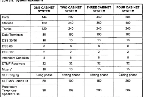
MAXIMUM CAPACITIES Some system maximum capacities are set by the number of available card slots in the cabinets; others are set by the system software. Table 2-2 lists all the maximum capacities. Not all of the maximums can be configured in the same system. For example; the maximum total number of DSS buttons in a system is 640.
Table 2-2. System Maximums
DTMF Receivers Mixers*
SLT Ringing
SLT MW Lamps Lit Proprietary
Telephone Speaker Use
32 32 32 32
10 10 15 15
6/ring phase 12/ring phase 18lring phase 24/ring phase
50 100 150 200
96 192 288 384
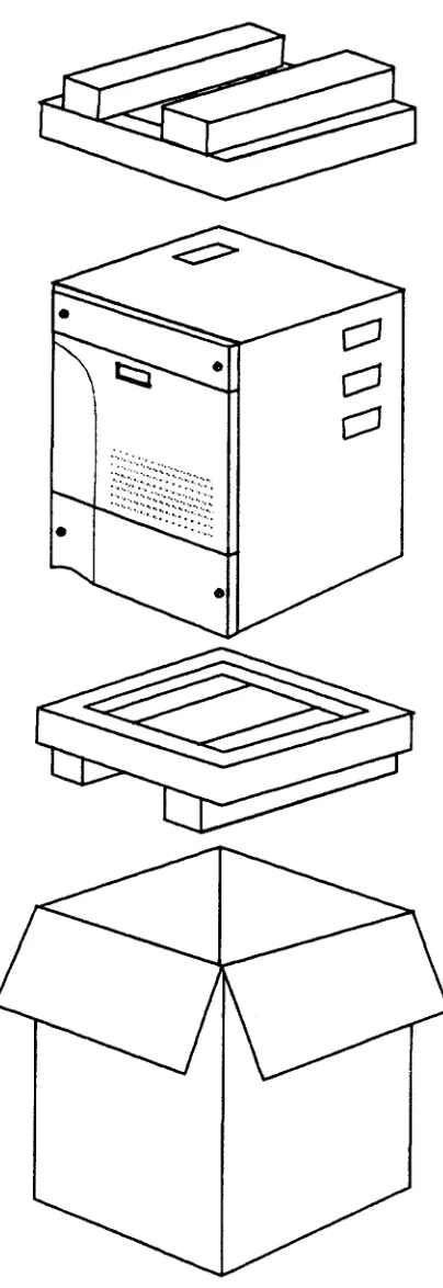
LIST OF MATERIALS Observe the following rules when unpacking and inspecting the system hardware:
. Inspect all shipping containers for evidence of damage that may have occurred during shipment. If such evidence is found, advise the carrier and distributor.
. Open the shipping containers and remove the contents carefully. Refer to Figure 3-l.
. Inspect the contents of the containers for any damage; if found, advise the carrier and distributor.
l When handling cards, do not remove them from antistatic bags
until card installation. Take normal precautions for electrostatic damage to CMOS devices (antistatic spray, grounding, etc.) Account for all system parts before discarding packing materials. Table 3-l at the end of this chapter contains a list of parts that should be shipped with each system.
TOOLS
You should have the following (customer provided) materials for installation:
. Mounting bolts; expansion bolts, or No. 10 bolts with insert sleeves, or No. 10 x 98 inch wood screws (minimum) . Ground wire from cabinets to MDF ground bar (12 AWG
stranded or solid)
l Signal ground wire from MDF to utility entrance ground (6 AWG
or larger, stranded)
. AC power outlet, 110 VAC, 15 Amps
. DC wire from battery plant to cabinet (10 AWG stranded or solid) No special tools are required for installation.
Figure 3-1. Unpacking the Cabinet
INSTALLATION SITE REQUIREMENTS
A stable, clean, and uncluttered area should be carefully considered when selecting an installation site. The equipment cabinets are designed to fit easily in the installation site. The cabinets are compact and operate quietly, so they can be placed in an office or work area.
Before the system can be installed, the operations in this chapter must have been completed.
Keep in mind the following environmental considerations in the selection of an installation site:
. The installation site should be clean, dry, and uncluttered to limit the intake of dust and dirt into the cabinet.
. The installation site should e well ventilated to dissipate warm air vented from the equipment cabinets.
. The installation site should be well lighted to make installation and maintenance easier.
. The installation site ambient temperature must be maintained between 32” and 104” Fahrenheit (0’ to 40” Celsius).
. The installation site should be maintained at a relative humidity between 10% and 90% (non-condensing) over the specified temperature range.
. The minimum wall load requirement for mounting a Series 3 cabinet is 55 pounds per cabinet.
. The equipment location should be subject to very little vibration
l There should be enough AC power outlets and circuits for the
system and its peripheral hardware.
. The equipment location should be free of overhead water pipes which might rupture and damage the equipment.
l The equipment location should be free of strong magnetic fields,
such as those created by large transformers. Also, avoid an area where there is apt to be static electricity.
l The equipment location must be free of corrosive fumes or
machine exhaust which might cause deterioration of circuit components.
. The equipment location should not have heating ducts or adjacent windows which could cause the ambient temperature to rise above or fall below the rated operating range.
. The equipment location must allow adequate air circulation through the cabinet.
SPECIAL INSTALLATION l Never install telephone wiring during a lighting storm.
INSTRUCTIONS .
Never install telephone jacks in wet locations unless the jack is designed for wet locations.
. Never touch bare telephone wires or terminals unless the telephone has been disconnected at the network interface. . Use caution when installing or modifying telephone lines.
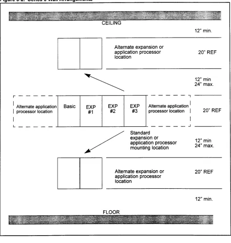
Figure 3-2 shows wall arrangements for the Series 3 system. WALL LAYOUT
igure 3-2. Series 3 Wall Arrangements
CEILING
12” min.
Alternate expansion or application processor
location 20” REF
r---
l ’ Alternate application
I processor location EXP #l
12” min 24” max.
EXP EXP
-Ll
Alternate application ’#2 #3 processor location I I
20” REF
--- J
Standard expansion or
application processor 12” min
mounting location 24” max.
Alternate expansion or application processor location
20” REF
12” min.
POWER REQUIREMENTS The power requirements are as follows:
l Voltage: 96 to 127 VAC
. Frequency: 60 Hz f 5 Hz . Phase: Single phase only . Maximum current:
- 3.8 A rated current for single cabinet system - 7.2 A for a two cabinet system
- 11 .O A for a three cabinet system - 14.4 A for a four cabinet system
. Power consumption (max):
- About 418 W for a single cabinet system - About 792 W for a two cabinet system - About 1210 W fora three cabinet system - About 1584 W for a four cabinet system
HEAT LOADING
GROUNDING REQUIREMENTS
. Typical heat generated:
- About 956 BTU (single cabinet/70 lines) - About 1853 BTU (two cabinet systeIl50 lines) - About 2809 BTU (three cabinet system/220 lines) - About 3703 BTU (four cabinet system)
Although standard power provides an acceptable level of performance for most installations, some will require the power failure transfer feature which switches designated stations to assigned outgoing trunks during power outages.
Some facilities (particularly those with computer installations) are equipped with an Uninterruptable Power Supply (UPS). This is the preferred power source since it provides automatic switchover to 120 VAC back up in case of a loss of power. If a UPS is available at the facility, the installer should verify that the Series 3 system power
outlet is connected to the UPS system.
Battery back up for the Series 3 is described in Chapter 8. . Signal ground: A single wire is connected to the G (center)
terminal of the terminal block in the bottom of cabinet zero (Basic). Refer to Chapter 4. This wire must be 12 AWG, stranded or solid copper conductor. The resistance of the connection from the terminal block to the Utility Entrance
Ground must not be greater than 5 ohms.
. Frame ground: Frame ground is provided by the third wire ground in the AC power cable. The brackets of cabinets
Table 3-1. Basic Cabinet Parts Lists
I
SPECIFICATION I COMMENTSCabinet
I
E2 IO-990-V02 1 1 Includes coversWall Mount Bracket
I
E2 10-9900-X1 56 1MPSU (Power Supply) (old) -or-
EMPSU (Power Supply) (new) RGMW (Ring Generator) ACPD (AC only)
DCPD (AC/DC)
Modem (2400 BPS Modem)
710036-01
710036-02
710038-01 E08B-1034-CO01 E08B-1034-Cl01
735077-05
Shipped in a separate box. Requires supplemental 24V supply.
Shipped in a separate box. Supplemental supply not required. Shipped in a separate box AC operation
AC operation with battery back up Attached to I/O port in cabinet
Music on Hold Adapter I 360456-01 1 Shipped in a separate box
4DMR* (4 circuit DTMF receiver) 1 E20B-4505-R350 I Shipped in a separate box 48V PS (-48~ Power Supply) I 710037-01 I Shipped in a separate box AC Power Monitor I E20B-9900-R370 I First and third cabinets only
* As an option, customers may order a 4DMR or a MUFN card.
Table 3-2. Expansion Cabinet Parts Lists
‘able 3-3. SSDEC Kit
PART SPECIFICATION COMMENTS
SSDEC El 6B-3020-R130
SSDEC Cable E660-2507-T673#00-01
E Ground Extender (short) E660-9900-T108 #I
E Ground Extender (long) E660-9900-T108 #2
E Ground Extender (short) E660-9900-T115 #I
GENERAL
WALL MOUNTING BRACKETS
Attaching the Mounting Bracket
Drilling the Mounting Bolt Holes
Wall Bracket Grounding
The following procedures detail the mounting of wall brackets, cabinets, and the connection of the inter-cabinet cables.
Each bracket will support one cabinet.
When planning the layout for a system with expansion cabinets located above or below the basic cabinet allow a minimum 12 inches between the top and bottom mounting brackets. The space is required for MDF cable clearance and cooling air flow. The
maximum spacing is 24 inches. Refer to Chapter Two.
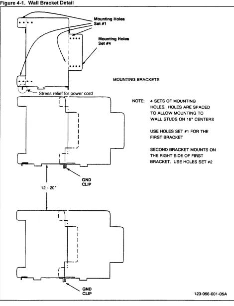
Each mounting bracket has four sets of bolt holes. Refer to Figure 4-l. Bolt Hole Set One is used to attach the bracket for the first cabinet in a row. Bolt Hole Set Two is used to attach the second cabinet bracket. The basic cabinet (cabinet zero) is always the first cabinet; expansion cabinet one mounts to the right of the basic cabinet. Attach the mounting bracket to the wall using either expansion bolts, or bolts and insert sleeves. The bolts must be at least 114 in. diameter; or, if mounting the bracket on wood, the minimum size wood screw permitted is a 114 x 5/8 inch. The method used to secure the bracket must be capable of supporting 55 pounds (25 kg).
Drill the bolt holes as follows:
1. Find and mark the stud locations behind the walls where the bracket is to be mounted. The mounting bracket provides holes for 16-inch center-to-center stud distance.
2. Mark the positions of the four holes to be drilled in the wall for the mounting bracket. For the basic cabinet use Bolt Hole Set
One.
3. Mark the center of the holes using a drill or punch.
4. Drill each marked hole to the correct depth and width for the bolts/sleeves or screws to be used.
5. If sleeve inserts are used, drive one into each of the holes. 6. If another bracket is to be installed to the right; attach the FIRST
bracket to the wall. Set the right bracket in place, next to the left bracket. Notice that two right side tabs fit under the main plate of the left mounting bracket. Align the Set Two holes in the new
bracket tabs with the Set One hole in the right side of the first bracket. Ensure that the left bracket frame ground tab is over the hole in the right bracket. Mark the wall through the Bolt Hole Set Two holes.
Figure 4-1. Wall Bracket Detail
Mounting Holes
set #4
MOUNTING BRACKETS
NOTE: 4 SETS OF MOUNTING
HOLES. HOLES ARE SPACED TO ALLOW MOUNTING TO WALL STUDS ON 16” CENTERS
USE HOLES SET #l FOR THE FIRST BRACKET
GND
BASIC CABINET 1. Unpack the basic cabinet as described in Chaoter 3. INSTALLATION (One-Piece
Front Cover) 2. To remove the front cover, turn key clockwise, swing top out to clear to locking tab, lift the cover up and out of the cabinet. Refer to Figure 4-2.
3. Tip cabinet onto its back. Loosen the screws holding the bottom plate. Slide bottom plate off of the screws. Refer to Figure 4-5. CAUTION: All covers must be replaced at the end of the
installation procedures to meet FCC Part 15 requirements.
BASIC CABINET
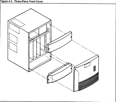
INSTALLATION (Three-Piece Front Cover)
1. Unpack the basic cabinet as described in Chapter 3. To remove the front cover, open the small lock cover, turn key clockwise, swing top out, lift the cover up and out of the cabinet. Refer to Figure 4-3.
2. Remove two screws from the top front cover. Remove top cover. Remove the bottom front cover the same way.
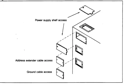
3. Remove the power supply shelf access port covers from the top of the cabinet. Refer to Figure 4-4.
4. Tip cabinet onto its back. Loosen the screws holding the bottom plate. Slide bottom plate off of the screws. Refer to Figure 4-5. CAUTION: All visible covers must be replaced at the end of the
installation procedures to meet FCC Part 15 requirements.
Fiaure 4-4. Access Port Covers
Power supply shelf access
extender cable access
/ Ground cable access
;--- ---- ---- ---
--L;-.--- ..-..--.-- -
INSTALLING THE EMPSU A Main Power Supply Unit (EMPSU or MPSU) is mounted in each cabinet. An MPSU (P/N 710036-01) requires a supplemental 24V power supply. When installing an EMPSU (P/N 71036-02) the supplemental power supply must not be installed.
1. Set the MPSU on the right side of the power supply shelf in the basic cabinet.
2. Align the MPSU with the connector on the backplane. Remove the access cover on the left side of the cabinet in order to see the connectors. Replace the cover after the MPSU is installed. 3. Slide the MPSU back until the connectors are seated.
4. Secure the MPSU with the M4xlO screw provided.
INSTALLING THE BASIC CABINET ON THE WALL BRACKET
The basic cabinet is ready to be installed on the wall bracket when the MPSU has been installed in the power supply shelf.
1. Lift and attach the cabinet by lining up the mounting slots in the top of the cabinet back with the tabs on the bracket and lowering the cabinet onto the mounting bracket as shown in Figure 4-6. 2. Use two screws and washers to fasten the equipment cabinet to
AC Power Monitor Install the AC Power Monitor plug in the backplane connector as shown in Figure 4-10.
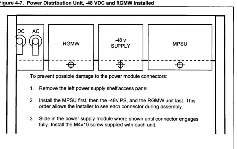
Ring Generator If a Ring Generator Message Waiting power supply is required to support single line phones, set the RGMW unit between the guide rails next to the ACPD or DCPD. Refer to Figure 4-7. Push the RGMW unit back until the rear edge connector is seated in the backplane connector. Secure with the M4xlO screw provided. The RGMW is installed in cabinet zero (Basic) and expansion cabinet two as needed.
-48 Volt Power Supply If a -48 volt power supply is required, set the unit between the guide rails next to the Main Power Supply. Push the -48 volt power supply back until the rear connector is seated in the backplane connector. Secure with the M4xlO screw provided.
On the bottom of the RGMW unit is the Message Waiting voltage strap. The RGMW is shipped with the strap in position WI.
NOTE: Do not cut the strap.
. Strap position WI is for US installations; message waiting voltage is 100~.
. Strap position W2 is for Canada installations; message waiting voltage is 13%.
NOTE: Refer to Table 2-l for further information on power supply indicators such as OPE, SYNC, etc.
Figure 4-7. Power Distribution Unit, -48 VDC and RGMW Installed
DC AC
SUPPLY MPSU
To prevent possible damage to the power module connectors:
1. Remove the left power supply shelf access panel.
2. Install the MPSU first, then the -48V PS, and the RGMW unit last. This order allows the installer to see each connector during assembly.
POWER AND GROUNDING
Power The AC power, DC power and ground connectors are located in the bottom of the cabinet. Refer to Figure 4-8.
Frame Ground The system wall mount brackets should be connected together. The frame ground tabs for side by side, or wire for installations. The ground connection for the frame is made through the third wire in the AC power cord. Verify that the AC receptacle dedicated to the Series 3 system is correctly wired and properly grounded.
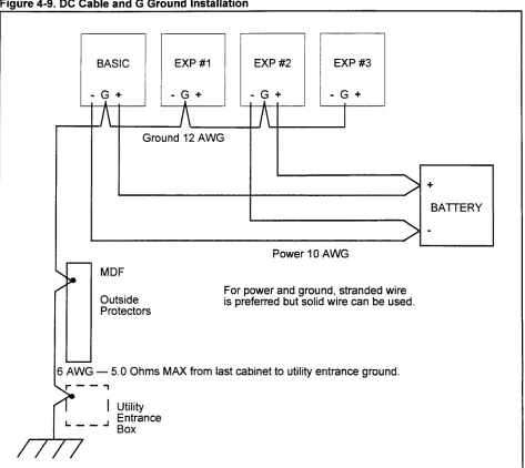
Signal Ground The signal ground wire must be connected from the G terminal on the DC terminal block to an MDF mounted ground bus bar. The DC resistance of the wire from the last cabinet to the utility entrance grounding point must be less than 5.0 ohms. Refer to Figure 4-9.
POWER BRACKETS
AC Cord Use the small straight bracket and nylon ties to provide strain relief for the AC power cord. The bracket is attached to the left ground tab of the wall mount bracket with the provided screw, washer, and nut. Align the dimple on the small bracket with the recess on the ground then tighten the screw. Attach the AC power cord with the nylon ties as shown in Figure 4-8.
DC Power Cables The conduit-monitoring angle bracket is used for the DC power cables when the system is equipped with battery backup. DO NOT ATTEMPT TO RUN THE MDF CABLES OR ANY OTHER CABLES THROUGH THIS BRACKET. If no conduit is installed, use the gromstrip to line the inside of the large hole to prevent damage to the cables. The angle bracket mounting slots allows the bracket to slide up and down to provide clearance for the DC power and ground terminal block. Refer to Figure 4-8.
Figure 4-9. DC Cable and G Ground Installation
1 I I I i I I 1 I I I
Ground 12 AWG
Power 10 AWG
+
BATTERY -
MDF
Outside Protectors
For power and ground, stranded wire is preferred but solid wire can be used.
j AWG - 5.0 Ohms MAX from last cabinet to utility entrance ground.
,r--7
I Utility L--J Entrance
INSTALLING EXPANSION CABINETS
The first expansion cabinet is mounted on the right side of the basic cabinet. The third and fourth cabinets can be installed to the right, above, or below the basic and second cabinet. Refer to Figure 4-1. Notice that expansion cabinet one is always mounted against the right side of the basic cabinet, and expansion cabinet three is mounted against the right side of expansion cabinet two.
installing the First Unpack the expansion cabinet as described in Chapter 3. Remove Expansion Cabinet the front door, front upper and lower covers, and the bottom cover
plate. 1.
2.
3.
4. 5.
6.
7.
8. 9.
10
Set all ACPD or DCPD switches to off. Remove power to the basic cabinet.
Remove the power supply assembly (MPSU part number 710036-01) from the right side of the basic cabinet power shelf. Remove the access port covers from the right side of the basic cabinet.
Remove the top access cover from the expansion cabinet. Remove the access covers from the left side of the expansion cabinet.
Mount and secure the expansion cabinet as described for the basic cabinet.
Route the power extender cable from the basic cabinet power supply shelf to the extension cabinet through the access ports. Refer to Figure 4-10. Seat plugs into the backplane connectors as shown.
Replace the top access cover on the expansion cabinet. Install the ground extender cables and the address extender cable as shown in Figure 4-10. Refer to Table 3-2.
Replace the MPSU in the basic cabinet. 11. Install the MPSU in the expansion cabinet. 12. Install the 48V PS in expansion cabinet. 13. Install RGMW as needed.
Fiaure 4-10. Ground Cable. Address Extension Cable
CONNECTED TO
* A Power extension cable * B Address extension cable
* C Ground extension cables: one 4-wire conductor, one 3-wire conductor * D SSDEC cable
* E ACD power monitor
* F Ground extension cables (SSDEC Kit): one 3-wire conductor, one 2-wire conductor
NOTE: Refer to Figure 4-8 for external power and ground connections.
installing the Second Unpack the expansion cabinet as described in Chapter 3. This will Expansion Cabinet be the third cabinet or second expansion cabinet. Remove the front
door, front upper and lower covers, and the bottom cover plate. 1. Set all ACPD or DCPD switches to OFF. Remove power from
the basic cabinet.
2. Remove the lower access port covers from the right side of the first expansion cabinet.
3. Remove the access port covers from the left side and the top of the second expansion cabinet.
4. Install the ACPD or DCPD in the second expansion cabinet. Refer to Figure 4-l 5. Replace power supply shelf access port cover.
5. Mount and secure the second expansion cabinet as described for the basic cabinet.
6. For snug mount cabinets install the short E ground extender cables as shown in Figure 4-l 0. For cabinets not snug mounted, install the long E ground extender cables. Use the access cover plates included with the cables. Ensure the grommets are installed in the cover plate cut outs. Refer to Figure 4-l 1 and Table 3-3.
Installing the Second 9. Install a 12 AWG ground wire from the G terminal of the second Expansion Cabinet (Cont’d) expansion cabinet to the G terminal of the first expansion
cabinet. Refer to Figure 4-9.
10. Verify that all ACPD or DCPD are set to OFF. Attach the AC power cord to the second expansion cabinet.
11. Verify that a SCPN4M card is installed in the basic cabinet. Route the long address expander cable from the SCPN4M card through the bottom cover plate near the I/O connectors. Route the cable up into the second expansion cabinet, to the SSDEC card. Use a M3 nut and star washer to secure the ground lug of the cable to the stud on the right side of the cabinets.
12. Refer to Chapter 8 for system start-up procedures. 13. Replace all covers and doors.
Installing the Third Unpack the expansion cabinet as described in Chapter 3. This will Expansion Cabinet be the fourth cabinet or the third expansion cabinet. Remove the
front door, front upper and lower covers, and the bottom cover plate. 1.
2.
3.
4.
5. 6.
7. 8. 9.
Set all ACPD and DCPD switches to off. Remove power from the basic and second expansion cabinets.
Remove the access port covers from the right side of the second expansion cabinet, and the left side of the third expansion cabinet.
Remove the power supply assembly (MPSU part number 710036-01) from the right side of the second expansion cabinet power shelf.
Mount and secure the third expansion cabinet as described for the basic cabinet.
Remove the top access cover from the expansion cabinet. Route power extender cable from the second expansion cabinet power supply shelf to the third extension cabinet through the access ports. Refer to Figure 4-10. Seat plugs into the backplane connectors as shown.
Install the MPSU in the third expansion cabinet. Replace the MPSU in the second expansion cabinet.
Install the address extender and ground extender cables. Refer to Figure 4-l 0.
10. Refer to Chapter 8 for system start-up procedures.
igure 4-l 1. Extended Cable Installation
BASIC t ST EXPANSION
-REMOVEANDREUSE
GROIIND EXTtNSlON CABLES
2ND EXPANSION CABLE’COVEF?
INSTALLING THE SFDC The Floppy Disk Drive Controller (SFDC) is required if the system is equipped with the optional floppy disk drive. The SFDC mounts on the CPU card. If not installed before shipment, proceed as follows. Refer to Figure 4-12.
1. Set the ACPD or DCPD switch(es) to OFF.
2. Remove the CPU card from the basic cabinet. Set the card on a padded surface, with an anti-static bag or anti-static foam sheet under the card.
3. Remove the SFDC from the anti-static shipping bag. 4. Align the connectors. Seat the SFDC onto the CPU card.
5. Install the included screws to secure the SFDC card. The screws must be installed to provide ground to the SFDC.
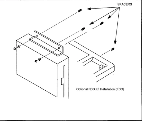
Installing the Floppy Disk The optional Floppy Disk Drive (FDD) is installed in the basic Drive cabinet only. Perform the following steps:
1. Connect the FDD cable to the FDD.
2. With the CPU card removed from the cabinet, align the FDD with studs on the right side of the cabinet.
3. Secure the FDD in place as shown in Figure 4-13. NOTE: Do not over-tighten the nuts.
4. Seat the FDD cable in the front connector of the SFDC card, located on the CPU card. (Refer to Figure 4-12.)
Figure 4-13. FIODDV Disk Drive Installation
POWER FAIL TRANSFER One Power Fail Transfer (GPFA) card can be installed in each cabinet. Align the card with the guides located on the left side of the cabinet under the card shelf. Push the card back until the 6PFA card edge connector is seated in the backplane. Seat the MDF cable connector and tighten the strain relief screw. Refer to Figure 4-14. Refer to Chapter 6 for cross connection information.
Installing the ACPD Installation is shown in Figure 4-15. Two types are available; AC or DCPD only operation, and AC/DC operation. Installation is as follows:
1. Remove the access cover from the top of the cabinet.
2. Remove the top access cover from the left side of the cabinet. 3. Set the ACPD or DCPD on the left side of the cabinet power
supply shelf.
4. Seat the cables in the backplane connectors.
5. Move the ACPD or DCPD to the left and push it back into the cabinet.
6. Install rear mounting screw with lock washer. 7. Replace the access cover on the top of the cabinet. 8. Install the cover on the left side of the cabinet.
Supplemental 24V This supplemental supply is required in systems equipped with the Power Supply MPSU. Systems equipped with with the EMPSU do not use this
supplemental power supply. Installation is shown in Figure 4-16. The supplemental power supply (E20B-9900-R410) is factory installed. Installation is as follows:
1. Remove the front covers and door from the cabinet.
2. Attach the supplemental power supply to the studs on the right side of the cabinet, under the lower card guide.
3. Route the cable as shown in Figure 4-16. 4. Seat the cables in the backplane connectors. 5. Replace the front cabinet covers and cabinet door.
Figure 4-16. 24V Supplemental Power Supply Installation
On the front of the 24V Supplemental Power On the front of the 24V Supplemental Power Supply is a green LED. The LED is dim at low Supply is a green LED. The LED is dim at low current loads (few digital phones). The LED is current loads (few digital phones). The LED is brighter at higher current loads (more digital brighter at higher current loads (more digital phones).
GENERAL Cabinet card location, common control cards, and system restart procedures are described in this chapter. A list of the maximum number of cards that can be installed in each cabinet is shown in Table 5-l. Refer to Chapter 8 for system power up, start up, and power down procedures.
COMMON CONTROL CARDS l SCPNZM: Combined processor, memory, switch network, and
optional floppy disk controller for use in one and two cabinet systems. Installed in the basic cabinet.
l SCPN4M: Combined processor, memory, switch network,
optional floppy disk controller, and switching extender for three and four cabinet systems. Installed in the basic cabinet, . SSDEC: Switching extender card for three and four cabinet
systems. Installed in the processor slot of the third cabinet. System status lamps, shown in Figure 5-1, on the CPU card, and include:
. RUN: Green; indicates that the system is operating without a major problem. This LED should light when the power supply is turned on.
. ALM (Alarm): Character display; indicates a minor or major problem (as an error code). These error codes are displayed sequentially starting as ’ - “, with the remainder of the code following. If more than one error is present, a period (“ “) will appear in the lower right corner of the display, faults will be displayed in order of priority, until the first one repeats.
. TO (Timer Overflow): Red; indicates a major CPU/memory or system problem.
Table 5-2 shows the designators and function of each of the system status buttons, switches, and status lamps located on the CPU card.
To set the DIP switch for default data base, refer to Table 5-3.
INTERFACE CARDS .
. . . . . . . . .
2APIA: 2 Circuit Application Processor Interface Card. 2TE4: 2 Circuit 214 Wire E&M Tie Trunk Card.
2lTE: 2 Circuit E&M Tie Trunk Card (man. discontinued) 2TTL: 2 Circuit Loop Dial Tie Trunk Card.
4BWC: 4 Circuit Central Office Bothway Trunk Card. 4CHT: 4 Circuit Character Trunk Card.
4DMR: 4 Circuit Dual-Tone Multi-Frequency Receiver Card. 4SLE: 4 Circuit Single Line (OPX) Telephone Card.
INTERFACE CARDS (Cont’d) l GPFA: 6 Circuit Power Failure Transfer Card, with ground start
. 8BWC: 8 Circuit Central Office Bothway Trunk Card.
l 8DTC: 8 Circuit Digital Telephone Interface Card.
. 8EKC: 8 Circuit Electronic Key Telephone Card.
. MUFN: Multi-Function Card (combines the 4DMR and 4EKC (% of 8EKC) card)
. 8SLC: 8 Circuit Single Line Telephone Card.
l 8PDL: 8 Circuit Positive Disconnect Line Card.
. 16SLC: 16 Circuit Single Line Telephone Card. . 16DTC: 16 Circuit Digital Telephone Interface Card. . 23PT: 23-Channel ISDN PRI Trunk Interface Card. . 24Tl: 24-Channel Digital Trunk Interface Card.
l CLKS: Clock Card.
. RVAC: Recorded Voice Announcement Card. . CACC: Call Accounting Card (Commercial).
l CACH: Call Accounting Card (Hospitality).
CAUTION: The 4BWC and 2lTL trunk circuits must be
protected by a sneak current fuse, ITW LV SCP-2, in all legs of each circuit. The fuse is designed to be mounted at the MDF in place of the normal bridge clips on a Reliance Electric or Siemens 66 block.
Table 5-I. Maximum Number of Cards per Cabinet
Single Line Analog Telephone - 8 circuit 8SLC 10 10 10 10 40 Positive Disconnect Line Card - 8 circuit 8PDL 10 10 10 10 40
Electronic Key Telephone - 8 circuits 8EKC/ 10 10 10 10 40
MUFN’
I
Digital Station - 8 circuits 8DTC lo- lo- lo- lo- 40-
5*3 5*3 5*3 El*3 20.3
Digital Station - 16 circuit 16DTC 8 8 8 8 32
Single Line Analog Telephone - 16 circuit 16SLC 8 8 8 8 32 n terface
Cards Bothway Trunk - 4 circuit 4BWC 10 10 10 10 40
Bothway Trunk - 8 circuit 8BWC 10 10 10 10 30.4
Tie Trunk, loop start - 2 circuit 2l-rL 10 10 10 10 40
Tie Trunk, 2 wire E&M - 2 circuit 2TTE 10 10 10 10 40 Tie Trunk, 4 wire E&M - 2 circuit 2TE4 10 10 10 10 40 Tie Trunk, 4 wire E&M - 4 circuit 4TE4 10 10 10 10 40
DID Trunk - 6 circuit 6DID 10 10 10 10 40
ISDN Digital Trunk - 23B+D 23PT 5 5 - - 10
T-l Digital Trunk - 24 channels 24Tl 5 5 5 5 10
DTMF Receiver - 4 circuic5 4DMR/ 8 8 8 8 8
MUFN
Character Trunk - 4 circuit 4CHT 2 2 2 2 4
Service
Cards Recorded Voice Announce Card RVAC 2 2 2 2 8
Application Processor Interface 2APIA 2 2 2 2 2
Clock Extracting (digital trunks) CLKS 1 - - - 1
Call Manager Card CACCiH 1 1 1 1 1
/ I
Power Fail / Power Fail Transfer 1 6PFA 1 1 j 1 1 1 ( 1 1 4
NOTES: 1. All system maximum capacities cannot be installed in one system.
2. Total includes both 8EKC and MUFN cards. The maximum number of MUFN cards per system is eight, based on the DTMF receiver portion of the card.
Figure 5-l. Front View of the CPU Cards
c
:.
. .
c
iI
l-l
NO DATA KEPT
R
El S T
DATA KEPT
BAlT Off
On
q
Ejector
RUN LED (Green) TO LED (Red)
ALM Display
IPL MODE SELECTION (COLD/HOT) Switch
RESET Button
DEFAULT DATA TYPE FD/RAM RESET SELECTION Switch
Ejector
Ejector
DEFAULT DATA TYPE DDTl
FD/RAM RESET DDTO
SELECTION Switch
RUN LED (Green) :+ 0 TO LED (Red)
ALM Display
NO DATA KEPT
IPL MODE SELECTION
B i
(COLD/HOT) Switch T
DATA UEPT
RESET Button Iw
SSDEC Cable Connector
Table 5-2. System Controls and Indicators CONTROLS/INDICATORS
Restart button
CPU toggle switch
DESIGNATOR FUNCTION
SET Push button which activates the
system restart
NO DATA SAVED (cold) Non-locking type switch which DATA SAVED (hot) specifies the restart mode CENTER (no restart) COLD: Initial start mode
HOT: Clear restart mode Default data type selection (DIP)
switch
System running lamp (green)
DDTO (switch 3) DDTl (switch 4) RUN
4-bit DIP switch (upper 2-bits are used to select default data type)
Glows steadily when the system is running without a major problem.
Alarm display ALM Alphanumeric single character display
of system error codes. Timer overflow lamp (red) . .
I
1 TO 1 Glows steadily when normal processor
program sequencing is interrupted.
BAT7 on/off jumper BAlT on/off Set the jumper to ON after system
power is applied. Move the jumper to OFF for shipping or extended storage (saved data on the card will be lost).
Table 5-3. IPL Select Switch
DIP SWITCH SETIING DDTO
(Switch 3)
DDTl (Switch 4)
Closed 1 Closed
Closed I Open
DEFAULT DATA RESULT
No default data base assigned - Set for FORMLOAD Load data base from floppy disk drive
Table 5-4. Line Card Specifications CARD 3sLc 3PDL 3EKC/ VlUFN :EKC 3oftion) 16SLC 8DTC 16DTC ISLE
LINE CARD SPECIFICATIONS Loop limit - 600 ohms (including telephone) Line leakage resistance - 15K ohms Loop limit - 600 ohms (including telephone) Line leakage resistance - 15K ohms Loop limit - 2000 ft.; 24 AWG Line leakage resistance - 15K ohms tiring - 4 wires/Proprietary telephone; XT-30 with OCHA
Loop limit - 600 ohms (including telephone) Line leakage resistance - 15K ohms Power: -24V
Ring Voltage: 80VAC superimposed on -24V Loop limit - 2000 ft.; 24 AWG
Line leakage resistance - 15K ohms tiring - 2 wires
Loop limit - 2000 ft.; 24 AWG ,ine leakage resistance - 15K ohms Wiring - 2 wires
Single line loop extension card - 1600 ohms ncluding the telephone
-ine leakaae resistance - 15K ohms
Table 5-5. Trunk Card Specifications
~CARD LINE CARD SPECIFICATIONS
2TE4 Signal - E&M, 2 and 4 wire compatible 4TE4
2lTE Signaling - E&M
Loop limit: Type I: 150 ohms Type II: 300 ohms 2l-rL Signaling - loop start and ground start
Loop limit: 3000 ohms
REMARKS 8 circuits
Analog, standard interface 8 circuits
Analog, standard interface 8 circuit / 4 circuits
Proprietary telephone: (CT-l O/20/30); Attendant Console; and DSS/BLF 40/80/l 00 console interface
16 circuits
Analog, standard interface
Digital simultaneous voice and data; telephone/ DIU interface
Accommodates the following:
. DS20, DS20S, DS20SD, and DS32SD . 8 CSDs or Digital Stations - voice only . 8 DIUs/DSS 30s
. 6 CSDs with DTA plus two Digital Stations/ CSDs without DTA or two DlUs
. Attendant PC console
16 circuits, voice or data on each circuit, not both . DS20, DS20S, DS20SD, and DS32SD . 16 CSDslDigital Stations/DIUs/DSS 30
l Attendant PC Console
4 circuits
Analog standard telephone Off premise extensions
REMARKS 2 circuits / 4 circuits E&M tie trunks 2 circuits
Analog tie lines E&M tie trunks 2 circuits
Analog tie lines and DID 4BWC Signaling - loop start and ground start
LOOD limit - 300 ohms
2 circuits
Analoa CO interface 6 circuits (DID only) 6DID Signaling - loop start and ground start
Loop limit - 600 or 900 ohms
8BWC Signaling - loop start and ground start 8 circuits
Loop limit: 3200 ohms Analog CO interface
24Tl Signaling -A/B bit 24 digital circuits
Frame format: DUESF 23PT Signaling - LAP B (#4ESS, #SESS, DMS 23 circuits (23B+D)
16 Circuit Digital Telephone Interface
Card (1 GDTC)
8 Circuit Digital Telephone Interface
Card (8DTC)
Table 5-6. Combination of Proprietary Telephones and Line Cards
The 16DTC card provides the interface circuitry for Digital Stations, CSDs, DSS 30s and/or Attendant PC Consoles. Each IGDTC card contains 16 circuits. The voice or data, data control signals, and power (-24V) are fed via one pair of wires. Each circuit provides one voice or data interface.
The 16DTC card also provides the interface for a Data Interface Unit (DIU). A DIU can be used to interface with data terminals through its RS-232C connector. In Hotel/Motel applications, it provides an interface port for an RS-232C compatible printer for providing Hotel/ Motel messages. Refer to Table 5-6.
The 8DTC card provides the interface circuitry for Digital Stations, CSDs, DSS 30s and/or Attendant PC Consoles. Each 8DTC card contains eight circuits. The voice/data, data control signals, and power (-24V) are fed via one pair of wires.
The 8DTC card also provides the interface for a Data Interface Unit (DIU). A DIU can be used to interface with data terminals through its RS-232C connector. In Hotel/Motel applications, it provides an interface port for an RS-232C compatible printer for providing Hotel/ Motel messages. Refer to Table 5-6.
INTERFACE CARD
16DTC 8DTC
DS TELEPHONE
Yes Yes
CSD TELEPHONE
VOICE ONLY VOICE and DATA
(no DTA) (with DTA)
Yes No
Yes Yes
DIU
8 Circuit Electronic Key Telephone Card (8EKC)
Multi-Function Card (MUFN)
8 Circuit Single Line Telephone Card (8SLC)
8 Circuit Positive Disconnect Line Card (8PDL)
16 Circuit Single Line Telephone Card (IGSLC)
The 8EKC card provides the interface circuit for proprietary
electronic key telephones, Attendant Consoles and Busy Lamp Field/ Direct Station Selection 40/80/l 00 button consoles. Each 8EKC card contains eight circuits. Each circuit serves one device via two pairs of wires. One pair is for analog voice transmission; the other for control signals along with the power for the terminal (-24V). When the loop limit from the Attendant Console exceeds 300 feet, an additional pair of wires is required. When the loop limit from the DSS 100 (in the case of one pair wiring) exceeds 1000 feet, an additional pair of wires is required.
Two consecutive circuits on this card are also required for the Off- Hook Call Announce feature for each CT-30 telephone.
The EKC portion of the MUFN card contains four electronic key telephone circuits. These circuits are identical to those on the 8EKC card. This card also contains four DTMF receiver circuits, equivalent to a 4DMR card.
The 8SLC card provides the interface circuitry for eight standard single line telephone sets, in addition to fax machines, modems, night bells, and dictation machines. Each 8SLC card contains eight circuits with each circuit serving one telephone set. An 8-bit microprocessor is on board and performs real time processing for the interface circuits. The loop resistance can be up to 600 ohms including the telephone set.
The 8PDL card provides disconnect supervision in conjunction with voice mail and dictation devices, as well as external conference bridge equipment. Each 8PDL card contains eight circuits with each circuit serving one telephone set. An 8-bit microprocessor is on board and performs real time processing for the interface circuits. The loop resistance can be up to 600 ohms including the telephone set.
The 16SLC card provides the interface circuitry for standard single line telephone sets, in addition to fax machines, modems, night bells, and dictation machines.
4 Circuit Single Line (OPX) The 4SLE card provides the interface circuitry for off-premise single Telephone Card (4SLE) line telephone sets. Each 4SLE card contains four circuits with each
circuit serving one telephone set. An 8-bit microprocessor is on board and performs real time processing for the interface circuits. The loop resistance can be up to 1600 ohms including the telephone
There is a switch option on the 4SLE card to select whether the circuit is used as a long line (loop resistance: 600-1600 ohms, including telephone set) or short line (loop resistance: up to 600 ohms, including telephone set). Each circuit has two switches. If both switches are set to the “Long” side, the circuit can be used for off premise extensions (OPX). Table 5-7 shows the available combination of long line and short line installation. Figure 5-2 shows the switch positions on the 4SLE card.
Table 5-7. Combination of Long/Short Lines
1 NUMBER OF SHORT LINES ( NUMBER OF LONG LINES 1
0
1
Upto 1
2 0
4SLE Card Switch Positions
Lul s
Circuit 3
Lm s
Circuit 2
Lms
Circuit 1
q Elo
Lms
Circuit 3
q un
Lms
Circuit 2
cln"
Lms
Circuit 1
Eln~
Lms
Circuit 0
0
Lms
Circuit 0
8 Circuit Central Office Bothway Trunk Card (8BWC)
The 8BWC card provides eight circuits of interface circuitry for public switched telephone Central Office (CO) lines. It has a balancing network selection option (short-default/long). Each 8BWC card, equipped with an a-bit microprocessor, contains eight interface circuits. Two types of signal supervision are provided; loop start and ground start. A loop of up to 2000 ohms including the CO equipment can be served.
Figure 5-3 shows the switch positions for the 8BWC card. 4 Circuit Central Office The 4BWC card provides the interface circuitry for the public Bothway Trunk Card (4BWC) switched telephone network of Central Office (CO) lines. Each
4BWC card, equipped with an a-bit microprocessor, contains four interface circuits. Two types of signal supervision are provided; loop start and ground start. A loop of up to 3200 ohms including the CO equipment can be served (at 48V, 20mA DC).
Figure 53. 8BWC Card Jumper Configuration
\ 0
,1+7 3),17 3$7 3)/1~3),17 3))l 7 3,,17 3\,1 7 3\
OQO ODO 0Qt-Y 0 0. OQO’ OQO O%QO ODO
I
JO00 JO01 JO02 JO03, ’ JO04 ’ JO05 JO06 JO070 I
/
/ I
/ I
/
--N I
Y \
I
/ ’ EXAMPLE ’ \ I
/ 1 2 3
i ‘\ I
I
Short I~
\ f
\ Long/
\ /
\ /
2 Circuit Loop Dial Tie Trunk The 2lTL card provides the interface circuitry for the direct Card (2TTL) connection between the system and another PBX, key telephone
system, or public network.
One 2lTL card, containing an 8-bit microprocessor, contains two circuits. A loop with up to 3000 ohms resistance including the distant end system (at -48V 20mA DC). These cards are available for Direct inward Dialing (DID) service.
2 Circuit E&M Tie Trunk Card The 2TTE/2TE4 card provides the interface circuitry for another PBX, (2TTE12TE4) key telephone system, or public network used in the Series 3
system (common carrier signaling equipment). The 2TTE card provides 2-wire transmission; the 2TE4 card provides changeable 2- wire/4-wire transmission. Each card, controlled by an 8-bit
microprocessor, has two interface circuits. A loop of up to 150 ohms resistance for Type 1, or 300 ohms for Type 2, including resistance of external interface, can be served. These cards are available to Direct Inward Dialing (DID) service.
Figure 5-4 shows the switch positions for the 2TE4 card
4 Circuit E&M Tie Trunk Card The 4TE4 card provides the interface circuitry for another PBX or key (4TE4) telephone system/public network used in the Series 3 system
(common carrier signaling equipment). The 4TE4 card provides 2- wire/4-wire transmission (changeable). One 4TE4 card, controlled by an 8-bit microprocessor, has four interface circuits. A loop of up to 150 ohms resistance for Type 1, or 300 ohms for Type 2, including resistance of external interface, can be served. These cards are available for Direct Inward Dialing (DID) service.
Figure. 54. 2TE4 Card Jumper Configuration
Jl J2
0
OPERATION JO00 JO01 JO02 JO03 JIOO JlOl JlO2 J103
2 Wire 2to 3 2to3 2to3 2to 3 2to 3 2to 3 2to 3 2to 3
Figure 55. 4TE4 Card Jumper Configuration
0
JO04 J104 J204 J304
0