726+,%$
Telecommunication Systems DivisionDigital Business Telephone Solutions
Installation and Maintenance
Manual
Software Release 4.1
and ACD
Software Release 3.1
Publication Information
Toshiba America Information Systems, Inc., Telecommunication Systems Division, reserves the right, without prior notice, to revise this information publication for any reason, including, but not limited to, utilization of new advances in the state of technical arts or to simply change the design of this document.
Further, Toshiba America Information Systems, Inc., Telecommunication Systems Division, also reserves the right, without prior notice, to make such changes in equipment design or components as engineering or manufacturing methods may warrant.
DKA-MA-IN/MT-VE 4025061
Version E, May 1999 (DK40i, Strata AirLink) Version D.4, January 1999 (Format change) Version D.3, November 1998 (Update TBDK-0022) Version D.2, October 1998 (Update TBDK-0021) Version D.1, September 1998 (Update TBDK-0019) Version C, October 1997
© Copyright 1999
Toshiba America Information Systems, Inc. Telecommunication Systems Division
All rights reserved. No part of this manual, covered by the copyrights hereon, may be reproduced in any form or by any means—graphic, electronic, or mechanical, including recording, taping, photocopying, or information retrieval systems—without express written permission of the publisher of this material.
Strata is a registered trademark of Toshiba Corporation. Stratagy is a registered trademark of Toshiba America Information Systems, Inc. Strata AirLink, Call Center Viewer are trademarks of Toshiba America Information Systems, Inc.
Trademarks, registered trademarks, and service marks are the property of their respective owners.
Strata DK
General End User Information
The Strata DK Digital Business Telephone System is registered in accordance with the provisions of Part 68 of the Federal Communications Commission’s Rules and Regulations.
FCC Requirements
Means of Connection: The Federal Communications Commission (FCC) has established rules which permit the Strata DK system to be connected directly to the telephone network. Connection points are provided by the telephone company— connections for this type of customer-provided equipment will not be provided on coin lines. Connections to party lines are subject to state tariffs.
Incidence of Harm: If the system is malfunctioning, it may also be disrupting the telephone network. The system should be disconnected until the problem can be determined and repaired. If this is not done, the telephone company may temporarily disconnect service. If possible, they will notify you in advance, but, if advance notice is not practical, you will be notified as soon as possible. You will be informed of your right to file a complaint with the FCC.
Service or Repair: For service or repair, contact your local Toshiba telecommunications distributor. To obtain the nearest Toshiba telecommunications distributor in your area, call Toshiba America Information Systems, Inc., Telecommunication Systems Division in Irvine, CA (949) 583-3700.
Telephone Network Compatibility: The telephone company may make changes in its facilities, equipment, operations, and procedures. If such changes affect the compatibility or use of the Strata DK system, the telephone company will notify you in advance to give you an opportunity to maintain uninterrupted service.
Notification of Telephone Company: Before connecting a Strata DK system to the telephone network, the telephone company may request the following: 1. Your telephone number.
2. FCC registration number:
♦ Strata DK may be configured as a Key or Hybrid telephone system. The appropriate configuration for your system is dependent upon your operation of the system.
♦ If the operation of your system is only manual selection of outgoing lines, it may be registered as a Key telephone system.
♦ If your operation requires automatic selection of outgoing lines, such as dial access, Least Cost Routing, Pooled Line Buttons, etc., the system must be registered as a Hybrid telephone system. In addition to the above, certain features (tie Lines, Off-premises Stations, etc.) may also require Hybrid telephone system registration in some areas.
♦ If you are unsure of your type of operation and/or the appropriate FCC registration number, contact your local Toshiba telecommunications distributor for assistance.
DK14 and DK40i
Key system: CJ6MLA-74479-KF-E
Hybrid: CJ6MLA-74478-MF-E
DK424
Hybrid: CJ69XA-10243-MF-E
Key system: CJ69XA-10242-KF-E
PBX: CJCHN-22757-PF-E
3. Ringer equivalence number: 0.3B. The ringer equivalence number (REN) is useful to determine the quantity of devices which you may connect to your telephone line and still have all of those devices ring when your number is called. In most areas, but not all, the sum of the RENs of all devices connected to one line should not exceed five (5.0B). To be certain of the number of devices you may connect to your line, as determined by the REN, you should contact your local telephone company to ascertain the maximum REN for your calling area.
RJ48C, RJ48X, RJ11, RJ14C, RJ21X (see Network Requirements in this document). Items 2, 3 and 4 are also indicated on the equipment label.
Radio Frequency Interference
Warning: This equipment generates, uses, and can radiate radio frequency energy and if not installed and used in accordance with the manufacturer’s instruction manual, may cause interference to radio communications. It has been tested and found to comply with the limits for a Class A computing device pursuant to Subpart J of Part 15 of FCC Rules, which are designed to provide reasonable protection against such interference when operated in a commercial environment. Operation of this equipment in a residential area is likely to cause interference, in which case, the user, at his/her own expense, will be required to take whatever measures may be required to correct the interference.
This system is listed with Underwriters Laboratory.
UL Requirement: If wiring from any telephone exits the building or is subject to lightning or other electrical surges, then secondary protection is required. Secondary protection is also required on DID, OPS, and tie lines. (Additional information is provided in this manual.)
Important Notice — Music-On-Hold
In accordance with U.S. Copyright Law, a license may be required from the American Society of Composers, Authors and Publishers, or other similar organization, if radio or TV broadcasts are transmitted through the music-on-hold feature of this telecommunication system. Toshiba America Information Systems, Inc., hereby disclaims any liability arising out of the failure to obtain such a license. CP01, Issue 8, Part I Section 14.1
Notice: The Industry Canada label identifies certified equipment. This certification means that the equipment meets certain telecommunications network protective, operational and safety requirements as prescribed in the appropriate Terminal Equipment Technical Requirements document(s). The Department does not guarantee the Equipment will operate to the user’s satisfaction.
Before installing this equipment, users should ensure that it is permissible to be connected to the facilities of the local telecommunications company. The equipment must also be installed using an acceptable method of connection. The customer should be aware that compliance with the above conditions may not prevent degradation of service in some situations.
Repairs to certified equipment should be coordinated by a representative designated by the supplier. Any repairs or alterations made by the user to this equipment, or equipment malfunctions, may give the telecommunications company cause to request the user to disconnect the equipment.
Users should ensure for their own protection that the electrical ground connections of the power utility, telephone lines and internal metallic water pipe system, if present, are connected together. This precaution may be particularly important in rural areas.
CAUTION! Users should not attempt to make such connections themselves, but should contact the appropriate electric inspection authority, or electrician, as appropriate.
CP01, Issue 8, Part I Section 14.2
Notice: The Ringer Equivalence Number (REN) assigned to each terminal device provides an indication of the maximum number of terminals allowed to be connected to a telephone interface. The terminal on an interface may consist of any combination of devices subject only to the requirement that the sum of the Ringer Equivalence Numbers of all the Devices does not exceed 5.
Contents
Introduction
Organization ... xv Conventions ... xvii Related Documents/Media ...xviii
Chapter 1 – DK14 Installation
Chapter 2 – DK40i Configuration
QSTU2A Standard Telephone Interface Unit ...1-15 QSTU2 Configuration ...1-15 QSTU2 Installation ...1-15 QSTU2 Programming ...1-16 QSTU2 Wiring ...1-16 QRCU3 DTMF Receiver/ABR Tone Detector Unit ...1-17 QRCU3 Configuration ...1-17 QRCU3 Installation ...1-17 QRCU3 Programming ...1-17 Built-in Auto Attendant ...1-18 Programming ...1-18 WSIU1 Serial Interface Board ...1-19 WSIU1 Installation ...1-20 WSIU Programming ...1-20 WSIU Wiring ...1-20 DK8/DK14 Compatibility ...1-21 DK14 Secondary Protection ...1-22 DK14 Wiring Diagrams ...1-23
Chapter 2 – DK40i Configuration
Chapter 3 – DK40i Installation
Chapter 3 – DK40i Installation
Chapter 4 – DK424 Configuration
Loop Limits ...3-39 DK40i Secondary Protection ...3-40 MDF Wiring Diagrams ...3-41
Chapter 4 – DK424 Configuration
System Configuration ...4-1 Base Cabinet ...4-2 Expansion Cabinets ...4-2 DK424 and DK280 Compatibility ...4-3 Designated Speaker OCA, DIU Data, and T1 slots ...4-4 DK280 to DK424 Upgrades ...4-5 Features Capacities ...4-6 System Capacity ...4-8 Printed Circuit Boards ...4-12 RKYS Feature Key Upgrades ...4-15 Telephones ...4-16 Attendant Position Options ...4-16 Direct Station Selection (DSS) Consoles and Door Phones (MDFBs) ...4-17 AC and Reserve Power Hardware ...4-18 Floor Mount Installation Hardware ...4-18 Worksheets ...4-19 Worksheet 1 – System PCB (Slot) Requirements ...4-20 Digital Ports Required ...4-20 Electronic Ports Required ...4-20 Standard Ports Required ...4-21 Station PCBs/Slots Required ...4-22 CO Line PCBs/Slots Required ...4-23 Attendant Console Slots Required ...4-26 PIOU/PIOUS/RSIU/RSSU Option Slots Required ...4-26 PEPU Page Option PCB Required ...4-26 System Slots Required ...4-27 Cabinets Required ...4-27 Worksheet 2 – System Cabinet Assignment Guide ...4-28 Worksheet 3 – System PCB Assignment Guide ...4-29 Worksheet 4 – Option Configuration Guide ...4-31 Worksheet 5 – System Power Factor Check ...4-34 Telephone/Device Power Factors ...4-36
Chapter 5 – DK424 Installation
Chapter 6 – DK424 T1
Power Supply Installation ...5-8 Power Supply (RPSU280 or RPSU424) Removal ...5-11 Power Supply Replacement ...5-11 Wall Mounting the Base Cabinet ...5-11 Base Cabinet (DKSUB424) Installation ...5-11 Expansion Cabinet Installation (DKSUE424) ...5-12 Cabinet Floor Mounting ...5-21 One or Two Cabinets ...5-21 Three or More Cabinets ...5-21 Cabinet Removal – Floor-Mounted Systems ...5-28 Cabinet Replacement ...5-28 AC Power and Grounding Requirements ...5-28 AC Power and Third Wire Ground Test ...5-29 Intercabinet Ground ...5-30 AC Power Cabling Installation ...5-30 AC Power for One or Two Cabinets (Wall Mount) ...5-30 AC Power for Three or More Cabinets (Wall Mount) ...5-31 AC Power for Three or More Cabinets (Floor Mount) ...5-31 Reserve Power Installation ...5-32 Reserve Power for One or Two Cabinets (Wall Mount) ...5-33 Reserve Power for Three or More Cabinets (Wall Mount) ...5-33 Reserve Power/AC Wiring for Three or More Cabinets (Floor Mount) ...5-34 Printed Circuit Board (PCB) Installation ...5-45 PCB Installation Considerations ...5-45 PCB Option Considerations ...5-45 RCTUA, RCTUBA/BB, RCTUC/D, RCTUE/F Common Control Units ...5-46 PCB Installation Power Supply Considerations ...5-46 Maximum Line Capacities ...5-47 Internal Hardware Options ...5-48 RCTU Installation ...5-51 RCTU Programming ...5-51 DK280 to DK424 Base Cabinet Upgrade Considerations ...5-52
Chapter 6 – DK424 T1
Chapter 7 – DK40i/DK424 Universal Slot PCBs
RDTU Cable Installation ...6-14 Loop Back Testing ...6-16 RDTU Self Test ...6-16 Network/CSU T1 Span Test ...6-16 Network/CSU/RDTU Span Test ...6-17 Performance Monitoring ...6-18 T1 Fault Isolation ...6-20 Flowchart Symbols ...6-21
Chapter 7 – DK40i/DK424 Universal Slot PCBs
Chapter 8 – DK40i/DK424 Universal Slot PCB Wiring
RDSU Installation ...7-37 RDSU Programming ...7-37 RDTU T1 Interface Unit ...7-38 REMU Installation ...7-39 PEMU Installation ...7-40 PEMU, REMU Programming ...7-40 RGLU2 Installation ...7-43 RGLU2 Programming ...7-43 RSIU, RSIS, RMDS RS-232/Modem Interface Unit ...7-45 RSIS, RMDS Piggy-Back Installation ...7-46 RSIU Installation ...7-46 RSIU, RSIS, RMDS Programming ...7-49 RSSU Installation ...7-51 RSSU Programming ...7-51 R48S -48 Volt Supply Installation (Internal Option) ...7-53 External Options ...7-54 RSTU2 Installation ...7-54 RSTU2 Programming ...7-55 RCMS Subassemblies Installation ...7-56 RMCU Installation ...7-58 RMCU/RCMS Programming ...7-59
Chapter 8 – DK40i/DK424 Universal Slot PCB Wiring
Station Wiring Diagrams ...8-2 Digital Station Wiring ...8-2 Electronic Station Wiring Diagrams ...8-9 Attendant Console Wiring Diagrams ...8-17 Analog Devices Wiring ...8-19 Power Failure Cut Through (DPFT) Wiring Pin-outs ...8-21 CO Line Wiring Diagrams ...8-23 DID and Tie Line Wiring ...8-29 Option Interface PCB Wiring Diagrams ...8-33
Chapter 9 – Station Apparatus
Chapter 9 – Station Apparatus
Chapter 10 – Peripheral Installation
Chapter 10 – Peripheral Installation
Chapter 11 – DK424 ACD Installation
RPCI-DI/PDIU-DI/PDIU-DS Data Communication Installation Tests ...10-66 DK Alarm Sensor ...10-75 Auto Attendant ...10-76 Strata DK Built-In Auto Attendant (AA) ...10-77 Non-built-in Auto Attendant ...10-84 Multiple PIOU, PIOUS, RSSU Installation ...10-84 Enhanced 911 Service (E911) ...10-86 E911 System Installation ...10-86 E911 Programming ...10-86
Chapter 11 – DK424 ACD Installation
Installation ...11-2 Multiple Serial Port Installation ...11-2 Wiring ...11-3 ACD Installation Guidelines ...11-4 ACD Line Operation/Programming Considerations ...11-7 ACD Programming ...11-7 Direct Incoming Assignments to ACD Groups ...11-7 DID/Tie/DNIS/ANI Incoming Line Calls ...11-7 Transfer From Built-in Auto Attendant (AA) to ACD Group ...11-7 Transfer From External AA to an ACD Group ...11-8 Overflow From an ACD Group Queue ...11-8 ACD Group Status ...11-9 Agent Ring No Answer Call Treatment ...11-10 ACD SMDR Printout Examples ...11-10 Insight DK (DK424 only) ...11-14 Call Center Viewer (CCV) ...11-14 Application Overview ...11-14 Strata DK Requirements ...11-15 Host PC Requirements ...11-15 Reference Information ...11-16 CCV Configuration ...11-16 Considerations ...11-16 Connectors ...11-16 CCV Configuration Instructions ...11-18 Connecting the DK to a Stand-alone CCV PC ...11-18 Connecting the DK to a Stand-alone CCV PC, More than 50 Feet Away ...11-19 Connecting CCV and SMIS ...11-20 Connecting Up to Three CCV PCs ...11-21 Connecting the CCV to More than Three CCV PC ...11-22 Spectrum Electronic Wall Boards ...11-24 Multiple Wall Boards ...11-24
Chapter 12 – Fault Finding
Chapter 13 – Computer Telephony Integration
DK424 RPSU280 Power Supply Test ...12-4 Station Cable Continuity Check ...12-7 Voltmeter Test ...12-7 Ohmmeter Test ...12-8 Cable Installation Test ...12-9 Fault Isolation Flowcharts ...12-10
Chapter 13 – Computer Telephony Integration
About Strata DK and TAPI ...13-1 Requirements ...13-1 StrataLink and TAPI Service Provider for Windows 95 ...13-2 Step 1: Remove Previously Installed DKT TAPI Service Provider Applications ...13-2 Step 2: Install TSPI and/or StrataLink Packages ...13-3 Step 2: Initialize StrataLink and the TAPI Service Provider ...13-4 Using StrataLink for CTI Connections ...13-6 StrataLink Operation ...13-6 DDE Commands ...13-9 Telephone System Events ...13-10 TeleMagic Link ...13-14 Testing TSPI Link ...13-14 CTI Application Bulletin Contents ...13-16
Chapter 14 – ISDN Interfaces
Chapter 15 – Hospitality Management Information System (HMIS)
Chapter 15 – Hospitality Management Information System (HMIS)
Chapter 16 – Strata AirLink Systems
Chapter 16 – Strata AirLink Systems
Chapter 16 – Strata AirLink Systems
RWIU Additional Information ...16-50 RWIU/WWIS Interface Unit ...16-50 Changing Initial Configuration ...16-59 Changing Communications Ports ...16-59 Checking RWIU and Base Station Software Versions ...16-60 Viewing Log Messages ...16-60 Resetting Base Stations and RWIU ...16-61 Upgrading RWIU and Base Stations ...16-61 Changing Base Station Numbers ...16-62 Charging Batteries ...16-62 Discharging Batteries ...16-63 Troubleshooting ...16-64 System Power, Polarity, and Continuity ...16-64 Components ...16-64 Communications ...16-64 RF Link Termination ...16-64 Noisy Circuits ...16-64 DC Resistance ...16-65 System Reset ...16-65 Activation Code ...16-65 Base Station ...16-65 Replacing a Defective Base Station ...16-67 Handset ...16-67 BSIA System ...16-73 RWIU System ...16-84 Base Station Specifications ...16-86 Handset Specifications ...16-87 Grounding Requirements ...16-88 FCC ...16-88 Part 68 ...16-88 Part 15 ...16-89 UTAM, Inc. ...16-89 Underwriters Laboratories (UL) ...16-91 Primary and Secondary Protectors ...16-91 System Line Circuit Requirements ...16-91
Glossary
... ... GL-1Introduction
This manual provides detailed step-by-step instructions for installing and maintaining the Strata DK14 / DK40i / DK424 digital business telephone systems. It is intended for qualified service technicians and system programmers. At the time of this printing, this book contains Release 4.1 information for the DK424. It also contains some pre-release information for software beyond Release 4.1.
Important! Information beyond Release 4.1 is preliminary and given prior to product release. Be careful when using this information as the software will change and updates/ additions will be required upon final release.
Use this manual in conjunction with the Strata DK Programming Manual which covers the programs related to the Strata DK systems discussed in this book.
Organization
In this manual, information specific to one system is clearly marked for that system whether in a chapter title or within a chapter (e.g., DK40i CO Line/Digital Telephone Interface Unit (KCDU) found in Chapter 7). Unmarked information should be considered to be general to all Strata DK systems discussed in this book.
This manual is organized into these sections/chapters for your convenience:
♦ Chapter 1 – DK14 Installation covers site requirements and explains how to install Strata DK14 Key Service Unit (KSU). Includes power requirements, cable lengths/network and grounding requirements.
♦ Chapter 2 – DK40i Configuration explains how to configure a Strata DK40i system. It also provides space to record the hardware and station devices that make up the system.
♦ Chapter 3 – DK40i Installation covers site requirements and cabinet installation information. Defines the installation site requirements necessary to ensure a proper operating environment for the Strata DK40i. Also included are input power requirements, cable lengths/network requirements, and grounding requirements. Explains how to install both the Base Key Service Unit (KSU) and the Expansion KSU. Instructions are also provided on how to remove and replace cabinets on installed systems.
♦ Chapter 4 – DK424 Configuration explains how to configure a Strata DK424 system. It also provides worksheets for determining hardware and station equipment placement and
requirements.
Organization
network requirements, and grounding requirements. Explains how to install both the Base and the Expansion Cabinets. Instructions are also provided on how to remove and replace cabinets on installed systems.
♦ Chapter 6 – DK424 T1 provides information on T1/DS-1 interfacing for the DK424.
T1/DS-1 interfacing is not available for the DK14 and DK40i.
♦ Chapter 7 – DK Universal Slot PCBs provides procedures for Strata DK40i/DK424 system
Printed Circuit Boards (PCBs) for installation into universal slots. It includes installation instructions, optional configuration information, and wiring and programming considerations for each PCB.
Note PCBs that cannot be installed into universal slots can be found in the installation chapter for the system (e.g., Chapter 3 – DK40i Installation).
♦ Chapter 8 – DK Universal Slot PCB Wiring contains point-to-point wiring diagrams for
connection of telephones, lines, peripheral equipment, and power supplies to the Strata DK systems.
Note Wiring diagrams for PCBs that cannot be installed into universal slots can be found in the installation chapter for the system (e.g., Chapter 3 – DK40i Installation).
♦ Chapter 9 – Station Apparatus provides instructions on how to connect telephones to the
Strata DK systems and how to configure and upgrade them for optional features. Procedures for installing direct station selection consoles, PC and conventional attendant consoles, and door phones also appear.
♦ Chapter 10 – Peripheral Installation provides connection procedures for optional peripheral
equipment to Strata DK systems. The instructions for each option include hardware requirements, PCB configuration, interconnection/wiring requirements, and programming considerations.
♦ Chapter 11 – DK424 ACD Installation includes installation instructions for Automatic Call
Distribution (ACD) and Management Information System (MIS) for the Strata DK424 (applies to all common control processors except the RCTUA). Includes installation instructions for Call Center Viewer. ACD and MIS is not available to the DK14 and DK40i.
♦ Chapter 12 – Fault Finding for troubleshooting and fixing problems.
♦ Chapter 13 – Computer Telephony Integration (CTI) contains CTI, TAPI, and System
Open Architecture Interface information. CTI application notes can be inserted here.
♦ Chapter 14 – ISDN contains an overview of the ISDN hardware with specific information on
the ISDN Primary Rate Interface (PRI) and Basic Rate Interfaces (BRI). It includes instructions for installation, hardware requirements, wiring requirements, and some programming considerations.
♦ Chapter 15 – Hospitality Management Information System (HMIS) gives you information
about HMIS, including installation, the Setup Utility, maintaining the HMIS databases and software, and troubleshooting.
♦ Chapter 16 – Strata AirLink Systems gives information about the external and integrated
wireless systems (BSIA and RWIU), including system components, installation of hardware and software, and troubleshooting.
Conventions
Conventions
Conventions Description
Note
Elaborates specific items or references other information. Within some tables, general notes apply to the entire table and numbered notes apply to specific items.
Important! Calls attention to important instructions or information.
CAUTION! Advises you that hardware, software applications, or data
could be damaged if the instructions are not followed closely.
WARNING! Alerts you when the given task could cause personal injury or death.
[DN] Represents any Directory Number button, also known as an extension or intercom number.
[PDN] Represents any Primary Directory Number button (the extension number for the telephone).
[SDN] Represents any Secondary appearance of a PDN. A PDN which appears on another telephone is considered an SDN.
[PhDN] Represents any Phantom Directory Number button (an additional DN).
$ULDO#%ROG Represents telephone buttons.
Courier Shows a computer keyboard entry or screen display.
“Type” Indicates entry of a string of text.
“Press” Indicates entry of a single key. For example: Type prog then press Enter.
Plus (+)
Shows a multiple PC keyboard or phone button entry. Entries without spaces between them show a simultaneous entry.
Example: Esc+Enter. Entries with spaces between them show a sequential entry. Example: # + 5.
Tilde (~) Means “through.” Example: 350 ~ 640 Hz frequency range.
➤ Denotes the step in a one-step procedure.
➤
Denotes a procedure.Used in a programming sequence to denote a variable LED button. A number on the black button represents a specific LED button.
Indicates continuation of a series of numbers entered.
See Figure 10
Grey words within the printed text denote cross-references. In the electronic version of this document (Library CD-ROM or FYI
Related Documents/Media
Related Documents/Media
Note Some documents listed here may appear in different versions on the CD-ROM, FYI or in print. To find the most current version, check the version/date in the Publication
Information on the back of the document’s title page.
The following documents and CD-ROMS can be used to reference further information about the Strata DK systems.
♦ Digital Telephone User Guide provides all the procedures necessary to operate
Toshiba-proprietary digital telephones, including Liquid Crystal Display (LCD) features. It also includes instructions for using the add-on module/DSS console.
♦ Digital Telephone Quick Reference Guide provides a quick reference for frequently-used
digital telephone features.
♦ Digital Single Line Telephone User Guide provides all the procedures necessary to operate
Toshiba-proprietary digital single line telephones.
♦ Electronic Telephone User Guide explains all the procedures necessary to operate
Toshiba-proprietary electronic telephones, including all LCD features. Does not apply to the Strata DK14 system. It also includes instructions for using the electronic DSS console.
♦ Electronic Telephone Quick Reference Guide provides a quick reference for
frequently-used electronic telephone features. Does not apply to the Strata DK14 system.
♦ Standard Telephone User Guide explains all the procedures necessary to operate rotary dial
and push-button standard telephones.
♦ Strata AirLink External Wireless Handset User Guide shows how to use the wireless
handset configured to standard ports of the Strata DK telephone system and many non-Toshiba systems.
♦ Strata AirLink External Wireless Quick Reference Guide contains instructions for
operation of commonly used Strata AirLink External Wireless Handset features.
♦ Strata AirLink Integrated Wireless Handset User Guide shows how to use the wireless
handset configured to digital ports of the Strata DK telephone system.
♦ Strata AirLink Integrated Wireless Quick Reference Guide contains instructions for
operation of commonly used Strata AirLink Integrated Wireless Handset features.
♦ System Administrator Guide gives instructions for the System Administrator to manage the
system. Contains instructions for Station Relocation, System Speed Dial, and other features only activated by the System Administrator.
♦ PC/Data Interface User Guide explains all the procedures necessary to operate stand-alone
data interface units while in the data mode for printer sharing and modem pooling. Also provides instructions on connecting to a Personal Computer with Telephone Application Programming Interface (TAPI).
♦ Cordless Telephone User Guide provides instructions on using the DKT2004-CT cordless
digital telephone as a single unit or in conjunction with a digital telephone.
♦ PC-DKT User Guide provides installation and operation information for the Personal
Computer Digital Key Telephone system.
♦ Strata DK Feature Description Manual describes each feature associated with the Strata
Related Documents/Media
♦ Keyprint 2000 User Guide provides instructions for the Keyprint 2000 software printing
package which allows you to print and store custom button label keystrips for Strata DK 2000-series 10-button or 20-button digital telephones, 20-button add-on modules, and 60-button digital DSS consoles.
♦ Strata DK Programming Manual provides all instructions necessary to program the system
and system record sheets, including ACD.
♦ Strata DK Installation & Maintenance Manual provides installation instructions for
configuring and installing the Strata DK14, DK40i and DK424. It also includes T1/DS-1 interface installation and configuration instructions, as well as fault finding flowcharts to troubleshoot the systems. An ACD Section provides instructions for installing ACD into the Strata DK424.
♦ Strata AirLink External Wireless System Installation Guide provides step-by-step
hardware and software installation instructions. It includes examples of system configurations, information on performing a site survey, and troubleshooting techniques.
♦ Hospitality Management Information System (HMIS) General Description provides an
overall view of the system’s hardware, software, applications and features. The HMIS is a PC-based solution, designed to meet the specific operational needs of small- to medium-sized hotel/motels and includes both the PC and software.
♦ Hospitality Management Information System (HMIS) User Guide describes the product’s
many software features and gives step-by-step instructions for using them.
♦ Strata DK Library CD-ROM enables you to view, print, navigate and search publications
for Strata DK14, DK40 and DK424 digital business telephone systems. It also includes Strata DK424 ACD Documentation, including the Strata DK424 Call Center Solutions General Description, ACD Agent Guide, ACD Supervisors Guide. ACD Installation and Programming instructions are included in the Strata DK Installation and Maintenance Manual and
Programming Manual.
♦ Strata DK HMIS CD-ROM contains a copy of all HMIS documentation/bulletins and
enables you to view, print, navigate and search publications.
♦ StrataControl CD-ROM contains the StrataControl software, that enables viewing,
downloading, editing, and uploading Strata DK programmed data on a PC. This software also provides a method of creating custom lists and user guides based on information from the Strata DK system. The CD-ROM contains the StrataControl User Guide.
♦ DKQuote CD-ROM contains the DKQuote application and the DKQuote User Guide that
shows how to use this interactive software to assist you with Strata DK Systems configuration and pricing worksheets.
♦ DKAdmin/DKBackup CD-ROM includes the programs that let you easily and quickly
custom program and/or update the Strata DK14/DK40/DK424 with a user-friendly PC display. The CD-ROM also contains the DKAdmin/DKBackup User Guide that explains how to use the DKAdmin/DKBackup interactive software applications. The current version does not support DK40i.
The following documentation and media applies to the Strata DK424 system only.
♦ Strata DK424 Call Center Solutions General Description provides a system overview,
including hardware and feature information. Highlights the technology employed in operating the ACD Strata DK424 system.
Related Documents/Media
♦ Insight DK CD-ROM which includes Insight DK software, the upgrade to Insight DK Plus,
Demo software, Insight DK documentation and training modules.
♦ Insight DK Installation Guide explains how to set up the network, install the server software,
install clients and explains how the data files are organized.
♦ Insight DK Supervisor Guide provides instructions for using the Strata DK Insight and
Insight DK Plus MIS for the Supervisor of a call center. Instructions for creating and using Real Time Displays, Reports, Alarms, and Wallboards are also included.
♦ Insight DK inView Quick Reference Guide provides instructions for viewing and
customizing the on-screen wallboard and large character views of the real time call center data.
♦ PC Attendant Console User Guide explains the procedures necessary to operate the PC
Attendant Console.
♦ PC Attendant Console Quick Reference Guide provides a quick reference for
frequently-used PC Attendant Console features.
♦ Call Center Viewer User Guide describes how to install and operate the Call Center Viewer
application on a PC. It explains how to view and customize ACD group and agent status information.
♦ Software MIS (SMIS) Supervisor Manual provides descriptions, examples, and instructions
on using the Software MIS application.
DK14 Insta
lla
tion
DK14 Installation
1
This chapter explains how to install the Strata DK14 system. It includes information on site requirements, wiring diagrams, and step-by-step instructions on how to install the unit(s), the ground wiring, AC power cabling, reserve power (battery backup) cabling, and PCB cabling.
Inspection
1. When the system is received, examine all packages carefully and note any visible damage. If any damage is found, do not open the packages. Contact the delivery carrier immediately and make the proper claims.
2. After unpacking (and before installing), check the system against the packing list and inspect all equipment for damage. If equipment is missing or damaged, contact your supplier
immediately.
3. Be sure to retain original packaging materials for re-use when storing or transporting system hardware.
Packaging and Storage
CAUTION! When handling (installing, removing, examining) PCBs, do not touch the back (soldered) side or edge connector. Always hold the PCB by its edges.
➤ When packaging and storing the system, remove PCBs from the system cabinet (the power supply may remain installed in the cabinet for storage and shipment). PCBs should be packaged in their original antistatic bags for protection against electrostatic discharge. Be sure to package equipment in its original shipping containers.
Site Requirements
Site Requirements
Input Power
The system requires an input power source of 115VAC ± 10VAC, 50/60 Hz, 10 amps. The AC outlet is recommended to be dedicated and unswitched, with a solid third-wire ground. (See “AC Power and Grounding Requirements” on Page 1-3 for details).
This is to eliminate interference from branch circuit motor noise or the like, and to prevent accidental power-off. To avoid accidental power turn-off, Toshiba recommends that you do not use an ON/OFF wall switch on this dedicated AC circuit.
For the DK14, a reserve power source (two customer-supplied 12-volt batteries) may be connected to the system to serve as a power failure backup.
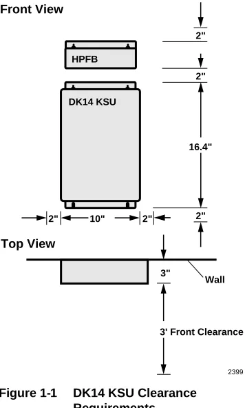
Clearance and Location
The minimum clearance requirements for the DK14 KSU are shown in Figure 1-1. The HPFB should be mounted directly above the D14 KSU.
Consider the following conditions when selecting a location for the KSU(s):
The location must be:
♦ Dry and clean ♦ Well ventilated ♦ Well illuminated ♦ Easily accessible
The location must not be:
♦ Subject to extreme heat or cold
♦ Subject to corrosive fumes, dust, or other
airborne contaminants
♦ Subject to excessive vibration
♦ Next to television, radio, office automation, or
high frequency equipment
2"
2" 16.4" Front View
Top View
3"
3' Front Clearance Wall 2"
DK14 KSU HPFB
2" 10" 2"
2399
AC Power and Grounding Requirements
DK14 Insta
lla
tion
AC Power and Grounding Requirements
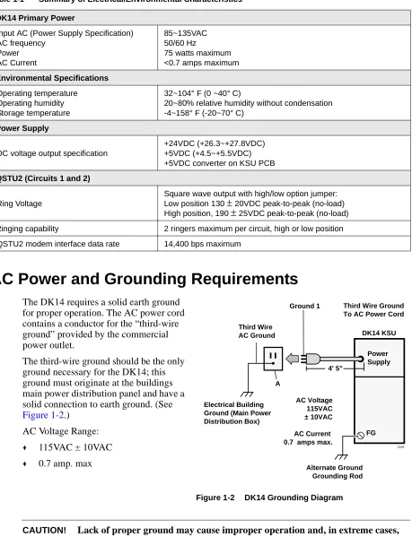
The DK14 requires a solid earth ground for proper operation. The AC power cord contains a conductor for the “third-wire ground” provided by the commercial power outlet.
The third-wire ground should be the only ground necessary for the DK14; this ground must originate at the buildings main power distribution panel and have a solid connection to earth ground. (See
Figure 1-2.) AC Voltage Range:
♦ 115VAC ± 10VAC
♦ 0.7 amp. max
CAUTION! Lack of proper ground may cause improper operation and, in extreme cases, Table 1-1 Summary of Electrical/Environmental Characteristics
DK14 Primary Power
Input AC (Power Supply Specification) AC frequency
Power AC Current
85~135VAC 50/60 Hz
75 watts maximum <0.7 amps maximum
Environmental Specifications
Operating temperature Operating humidity Storage temperature
32~104° F (0 ~40° C)
20~80% relative humidity without condensation -4~158° F (-20~70° C)
Power Supply
DC voltage output specification
+24VDC (+26.3~+27.8VDC) +5VDC (+4.5~+5.5VDC) +5VDC converter on KSU PCB
QSTU2 (Circuits 1 and 2)
Ring Voltage
Square wave output with high/low option jumper: Low position 130 ± 20VDC peak-to-peak (no-load) High position, 190 ± 25VDC peak-to-peak (no-load) Ringing capability 2 ringers maximum per circuit, high or low position
QSTU2 modem interface data rate 14,400 bps maximum
Power Supply
FG Third Wire
AC Ground
Ground 1 Third Wire Ground To AC Power Cord
DK14 KSU
A
Electrical Building Ground (Main Power Distribution Box)
Alternate Ground Grounding Rod AC Voltage
115VAC ± 10VAC
AC Current 0.7 amps max.
2159 4' 5"
AC Power and Grounding Requirements
AC Power and Third-wire Ground Test
Test the “third-wire ground” for continuity by either measuring the resistance between the third prong terminal (earth ground) and a metal cold water pipe (maximum: 1 ohm), or by using a commercially available earth ground indicator. If neither procedure is possible, perform the following earth ground test procedure.
➤ To perform the earth ground test procedure
1. Obtain a suitable voltmeter, and set it for a possible reading of up to 250VAC.
2. Connect the meter probes between the two main AC voltage terminals (white and black wires) on the wall outlet. The reading obtained should be between 100~125VAC.
3. Move one of the meter probes to the third terminal (green wire ground). Either the same reading or a reading of zero volts should be obtained.
4. If the reading is zero volts, leave one probe on the ground terminal and move the other probe to the second voltage terminal.
CAUTION! If a reading of zero volts is obtained on both voltage terminals (white wire to green wire, black wire to green wire), the outlet is not properly grounded. Omit Steps 5 and 6, and see following CAUTION!
5. If a reading of zero volts on one terminal, and a reading of 105~125VAC on the other terminal is obtained, remove both probes from the outlet.
6. Set the meter to the “OHMS/Rx1” scale. Place one probe on the ground terminal, and the other probe on the terminal that produced a reading of zero volts. The reading should be less than 1 ohm.
CAUTION! If the reading is more than one ohm, then the outlet is not adequately grounded. If the above tests show the outlet AC voltage is not in range or is not properly grounded, the condition should be corrected (per Article 250 of the National Electrical Code) by a qualified electrician before the system is connected.
Alternate or Additional Ground
If the “third-wire” AC ground can not practically be improved or if extreme motor noise or other disturbance causes system malfunction, or if local area lightning storms exist, a separate direct ground may be warranted.
Connect a separate earth ground from a cold water pipe or earth grounding rod directly to the FG screw terminal on the DK14 power supply (see Figure 1-2).
This chapter provides the instructions necessary to mount the DK14 Key Service Unit (KSU). Instructions are also provided on how to remove and replace the power supply.
KSU Mounting Considerations
DK14 Insta
lla
tion
KSU Mounting Considerations
The KSU is designed to be mounted on a wall or other vertical surface. Toshiba recommends using the following method.
Pre-installation
1. Loosen the screws on the front cover of the KSU, and remove the cover (Figure 1-3). 2. Move the SW1 RAM Storage Battery jumper
plug strap on the motherboard to the ON position (Figure 1-4).
3. If the DK14 is less than one mile from the central office (or PBX), set the CO line PAD switches, SW401 and SW451, to the PAD position to provide a 3db level loss to avoid excessive loudness.
4. Install all optional PCBs per instructions later in this chapter.
AC DC 6.87 10" Front Cover Screws (4) 16.3 6.7 Wall Mount Screws (4) 2361
Figure 1-3 DK14 Dimensions
J15 QRCU J11 J14 J10 QCDU#2 QCDU#1 J9
0 PAD 3
NOR BNPAD
0 PAD 3
NOR BNPAD SW401 SW451 QSTU J12 QSTU J13 VR701 J19 J21 WSIU J20 WSIU J2 C01 J7 J8 QSTU SW1 Off On QSTU J16 QRCU J3 C02 FG FG BAR 25-pair Female Amphenol Connector (to Station Tip/Ring and Relay Contact)
SW451 (CO1) SW401 (CO2): 3-db PAD Switches for CO Line 1 and 2
2404
Modular Jack Cover Holders
System Frame Ground Bar DK14 Main Printed Circuit Board
J3, CO Line 2 Modular Jack (RJ11)
KSU Mounting Considerations
Mounting the KSU
1. Make sure the power supply switch is turned OFF.
2. Place the KSU on the desired location on the mounting surface and mark the location of the four screw holes (there is one on each corner). See Figures 1-3 and 1-5.
3. Make sure the location of the KSU meets the minimum clearance requirements. 4. Drill holes on these marks.
5. Secure screws approximately two thirds of the way into the top two holes on the mounting surface.
6. Hang the unit from the top two screws and then secure the screws completely into the mounting surface.
7. Finish securing the unit to the mounting surface by completely screwing the bottom two screws into the wall. 8. Ground system according to previous
“AC Power and Grounding
Requirements” on Page 1-3 instructions. 9. Connect applicable wiring (modular CO line cords, 25-pair amphenol connector cable, etc.) to the KSU. Route the wiring as shown in Figure 1-6, and then fasten wiring to the unit with the tie wraps that come with the KSU. (See Figures 1-16~1-18 for additional wiring details.)
Note Figure 1-6 shows cables routed to the right; they may also be routed to the left, depending on the location of the MDF.
10. If the Reserve Power Battery and Charger (HPFB) is going to be installed, refer to the following section. If not, proceed to Step 11.
11. Plug the AC power cable into an outlet and then turn ON the DC power supply switch. 12. Reinstall the front cover onto the KSU.
Stud
Plasterboard Hard Board
(1/4 inch plywood)
DK14 KSU
2360
Reserve Power Battery
DK14 Insta
lla
tion
Reserve Power Battery
A second HPFB can be installed directly above the unit to supply backup reserve power.
➤ To install the Reserve Power Battery and Charger (HPFB) 1. Place the HPFB directly above the DK14 KSU (Figure 1-7). 2. Mark the location of the two screw holes, then drill holes. 3. Screw the two screws two-thirds into the mounting surface.
4. Hang the HFPU on the screws then tighten the screws into the mounting surface. 5. Plug the first HPFB connector into BATT connector on the right side of the KSU. 6. Connect a ground wire from the HPFB “FG” screw to the DK14 QPSU8 screw labeled
“HPFB6.” The ground wire can be fed through the opening by the AC power cord.
Note The DK14 should be plugged into AC power and the DC power switch should be turned ON. The HFPU will not start to operate if AC power is not available during the initial installation.
O —
AC Power Cord and Plug 4' 7"
Station Tip/Ring Amphenol 25-pair Jack (female)
Left Side View Right Side View
RJ11 CO Line Jacks RS-232 Interface Jacks, TTY, Caller ID, SMDR DC ON/OFF Power Switch Reserve Battery (HPFB) Connector
RJ11 Power Failure Transfer Jack
BATT
DC
SI01 SI02
Tie-wrap supplied to Hold Amphenol Connector
CO4
CO2
CO1
CO3
PFT
To HPFB FG Screw
3"
2397
Tie-wrap Holder
Tie-wrap Holder
Power Supply Removal and Replacement
8. Dress and tie-wrap the HPFB cables.
9. To mount a second HPFB, repeat Steps 1~4, then plug the second HPFB connector in the first HPFB and connect an FG wire between each HPFB FG screw.
10. To test the HPFB, remove the DK14 AC plug from the AC outlet. The DK14 AC LED will go out, but the DK14 DC LED remains on. Also the system remains in normal working order and the HPFB 24V LED remains on.
11. If it is desired to turn off the HPFB (after loss of AC power), use a pencil or other sharp object to press the Battery OFF switch.
CAUTION! Once the HPFB is turned OFF or unplugged (during AC power loss) it will not operate again until AC power is restored to the DK14 KSU.
Power Supply Removal and Replacement
The power supply comes factory-installed in the KSU; if necessary, it can be removed and replaced.
Power Supply Removal
1. Make sure that the power supply switch is OFF and that the AC power cable is not plugged into an outlet. Confirm that green AC LED is not lit. See Figure 1-8.
2. Loosen the screws on the front cover of the KSU, and remove the cover.
3. Unplug HPFB cable from BATT connector of power supply and disconnect the HPFB ground wire.
AC
DC
AC Power Cord/Plug 4' 7"
To Second HPFB (optional)
Second HPFB Connector
FG Screw
Tie-wrap
Note
Do not run power cables with station and CO line cables.
DC Power Switch Tie-wrap
Battery Connector HPFB Unit:
Reserve Power Battery and Charger (optional)
HPFB FG Wire
2403
Power Supply Removal and Replacement
DK14 Insta
lla
tion
4. Unplug the AC cable from the CN1 connector on the power supply.
5. Remove the FG screw, and disconnect the green third wire ground ring terminal. 6. Unplug the DC cable from the CN3 connector on the power supply.
7. Remove the top two, and bottom left corner screws that attach the power supply to the KSU. Remove power supply.
Power Supply Replacement
1. Set the power supply in its proper place in the KSU. See Figure 1-8.
2. Secure the power supply to the KSU with the top two, and bottom left corner screws. 3. Install the green third wire ground ring terminal with the FG screw.
4. Plug the AC cable into the CN1 connector on the power supply. 5. Plug the DC cable into the CN3 connector on the power supply.
6. Plug the AC power cable into an outlet and turn ON the power supply switch.
7. Test QPSU8 power supply according to Chapter 12-Fault Finding, “DK14 Hardware Fault Isolation procedure.”
8. Plug HPFB cable into BATT connector of power supply and reconnect the HPFB ground wire. 9. Reinstall the cover on the KSU.
WARNING
Hazardous voltage inside !If servicing required, remove A.C. cord.
AC
DC CN2
J19 FG CN3
HPFB6
CN1
2401
F.G. Screw for Third Wire Ground Connection to Power Supply
QPSU8 Power Supply
Power Supply Mounting Screw
ACN1 Power Cord Connector
Power Supply Mounting Screw HPFB Ground Wire To HPFB6
FG Screw DC Power On/Off Switch
CN2, J19 Power Supply Connectors and Cable AC and DC
Power Indicator LEDs
F201, 3 Amp Fuse Non-replacable
Yellow Wires (+24V)
Battery Connector for HPFB Power Supply
Mounting Screw
CN3, Battery Connector Plug
Printed Circuit Board (PCB) Installation
Printed Circuit Board (PCB) Installation
This section provides procedures for installation of Strata DK14 system optional printed circuit boards (PCBs) into the KSU. This includes installation instructions, optional configuration information, and wiring and programming considerations for each PCB.
Be sure the ground has been checked. (See “AC Power and Grounding Requirements” on Page 1-3.)
PCB Installation Considerations
The Strata DK14 KSU comes standard with four digital telephone circuits (ports) and two CO line circuits. These circuits, along with the common control unit, are built into the motherboard.
KSU Option PCBs
The DK14 KSU can support up to four optional PCBs, including:
♦ A maximum of two QCDU2s: each one provides one CO line circuit and two digital telephone
circuits.
♦ A QSTU2 which provides two standard telephone circuits (ports).
♦ A QRCU2 which provides three circuits to receive DTMF tones (required for DISA and
devices connected to QSTU2s), and three circuits to detect busy tone (required for the ABR feature).
♦ A WSIU which provides a port for either a Station Message Detail Recording (SMDR) device
or a maintenance terminal or modem, or Caller ID interface.
♦ The KSU does not come from the factory with any option PCBs installed. Each of the option
PCBs must be installed in specific locations. (See Figure 1-9.)
PCB Option Considerations
PCBs may be configured for a variety of hardware and software options. Hardware options are defined as either internal (generally related to optional PCB subassemblies) or external (related to connection of peripheral equipment such as background music, voice mail, etc.). Hardware and software options for each PCB are identified in the individual PCB installation procedures in this chapter.
PCB Hardware Options. Each PCB must be configured for the applicable hardware options prior to installation of the PCB. Configuration instructions for internal hardware options are provided in the individual PCB installation procedures in this chapter. Configuration instructions for external hardware options are provided in Chapter 10 – Peripheral Installation.
PCB Software Options. After installation of the PCBs in the KSU, configure the PCBs for software options through programming. A programming overview for each PCB is provided in the individual PCB installation procedures in this chapter. Refer to the Strata DK Programming Manual for detailed instructions.
PCB Installation/Power Supply Considerations
Printed Circuit Board (PCB) Installation DK14 Insta lla tion J15 QSTS1A J1 J11 J4 J14 J6 J8 J1 F.G. STU STU J7 J5 WARNING
Hazardous voltage inside ! If servicing required,remove A.C. cord. HPFB6 QCDU2A QKYS J2 J10 J20 J3 J21 J4 J1 SW101 CO4 SIO 1 SIO 2 DC BATT QRCU3A Component Side CO2 J6-25 Pair Amphenol Jack (female) for Telephone Tip/Ring and Relay Contact CO3 CO1 PFT, RJ11 Modular Jack 6-wire RJ11 Modular Jacks 6-wire RJ11 Modular Jack 1 or 2 HPFB reserve power units System Frame Ground Bar AC DC QCDU2A MOH Jack MOH Volume Control 600 ohm Page Not Used F.G. J9 J1
0 PAD 3 SW101
SW1 190 130 J2 STU J12 J3 STU J13 QSTU2A QSTS2A VR701 J22 2364 WSIU1A
0 PAD 3
Built-in CO Line, Digital, Telephone, and Other Circuits
Built-in CO Line, Digital, Telephone, and Other Circuits
The KSU comes standard with two CO lines and four digital telephone circuits already installed on the motherboard (WMAU). See Figure 1-4 for an illustration of the WMAU.
Built-in CO Line Circuits
The two standard loop start CO line circuits are integrated into the KSU motherboard WMAU and are identical to the QCDU2 CO line circuits.
CO lines that receive Caller ID must be cross-connected to the TC-1041 (MLX-41) Caller ID interface box (See Page 1-19 for address). See Figure 1-18 for wiring.
Built-in Digital Telephone Circuits
The four digital telephone circuits that come standard with the system are integrated into the motherboard in the KSU. These circuits are identical to the digital circuits found on the QCDU2. The motherboard does not have to be configured for the digital circuits to operate.
KSU Motherboard CO Line/Digital Station Circuit Wiring
See Figures 1-15~1-17 for details.
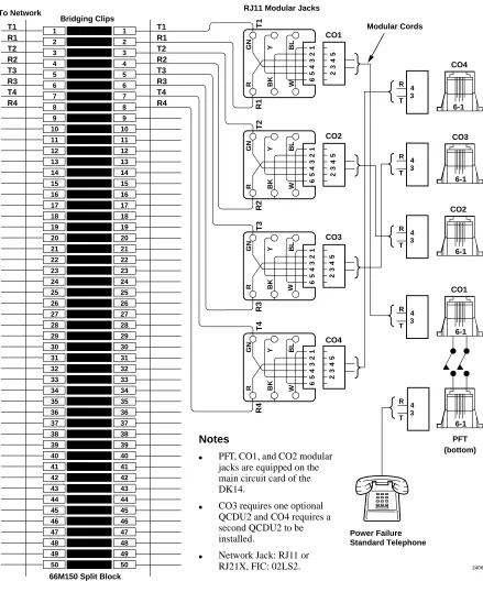
Power Failure Telephone Installation
1. Remove the RJ11 cover (Figure 1-11) from the PFT jack and store the jack cover. 2. Connect the power failure telephone (500/2500-type standard telephone to the PFT jack.
Figure 1-17 shows the DK14 MDF to CO Line Wiring.
Music-On-Hold (MOH)/Background Music (BGM) Source Connection
Connect the MOH/BGM source to the MOH RCA jack (Figures 1-9 and 1-16) in accordance with Music Source Configuration A in Chapter 10 – Peripheral Installation.
External Page Output Connection
QCDU2 CO Line Digital Telephone Interface Unit
DK14 Insta
lla
tion
QCDU2
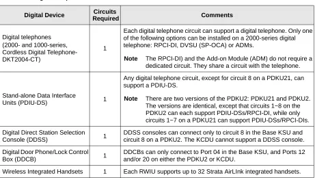
CO Line Digital Telephone Interface Unit
Circuits per PCB: one loop start CO line circuit and two digital telephone circuits
Interfaces with: digital telephones
PDIU-DIs/PDIU-DI2s/RPCI-DI
ADMs connected to the telephones and PDIU-DSs Does not support a DDSS console or DDCB
Older Version(s): QCDU1A
QCDU2 Configuration
The QCDU2 may have to be configured to control excessive loudness if the system is close to a CO or installed behind a PBX telephone system. It does not have to be configured for anything else. The decibel (db) PAD switch, SW101 controls the loudness by providing a 3 db signal level drop to, or from, the PBX or CO when set to the PAD position. The switch comes from the factory set at 0 (for no PAD) meaning no PAD loss.
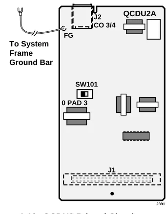
QCDU2 Installation
A maximum of two QCDU2 PCBs can be installed in the KSU.
➤ To install the QCDU2
1. If the system is located within one mile of the CO or PBX telephone system, set db PAD switch SW101 to the PAD position.
2. Make sure that the power supply switch is OFF.
3. Slide QCDU2’s front edge and FG wire under the System Frame Ground Bar; align and insert the QCDU2 connector J1 into the motherboard connector (J9 for CO3 first, J10 for CO4 second). (See Figure 1-10)
Apply firm, even pressure to ensure proper mating of the connectors. Make sure the QCDU2’s connector edge next to the connector J1 snaps firmly into the standoffs on the KSU motherboard. (See Figure 1-4).
4. Connect the Frame Ground (FG) lead from the QCDU2 to the screw nearest the QCDU2 located on the system Frame Ground bar. Remove the “knock-out” from the KSU cover CO3 or CO4 access slot, and store the “knock-out” in the slots provided in the KSU base. (See
Figure 1-11.)
FG J2 CO 3/4
0 PAD 3 SW101
2391
To System Frame Ground Bar
QCDU2A
J1
QCDU2 CO Line Digital Telephone Interface Unit
QCDU2 Programming
The following parameters may be specified through programming for the QCDU2.
Program 10-1: Allows/denies two-CO Line Conference and Direct Inward System Access (DISA). Program 15: Auto Release detection; DISA, and other attributes to the CO line.
Program 16: Assigns CO line to groups 81~84, and dial 9 group.
Program 40: Assigns stations access to CO line (incoming and outgoing access). Program *50: Assigns Caller ID CO lines to Caller ID interface CO line.
Program *51: Assigns station to Caller ID, Lost Call memory.
Modular Jacks
C02 Cover
C01
PFT
Knock out PFT jack cover when QCDU, SMDR/TTY is installed
Take out jack cover when PFT is connected
Store the jack cover in the jack cover holder
Reinstall the jack cover when the PFT telephone is unplugged
2392
Side View
Front View
1
2
3
4
QSTU2A Standard Telephone Interface Unit
DK14 Insta
lla
tion
QSTU2A
Standard Telephone Interface Unit
Circuits per PCB: two standard telephone circuits
Interfaces with: standard telephones Auto Attendant devices
separate BGM source connection voice mail machines
facsimile machines
Older Version(s): QSTU1A
Note For the system to recognize the Dual-Tone Multi-Frequency (DTMF) tones generated by standard telephones (or any other device connected to a QSTU2 port), a QRCU3 must be installed.
The QSTS2 PCB is factory-installed on the QSTU.
QSTU2 Configuration
The QSTU2 does not require configurations for the ring generator voltage level. Most standard telephones and two-wire devices require 190; however, some devices may experience ring-trip at 190, and should be set at 130.
QSTU2 Installation
1. Make sure the power supply switch is OFF.
2. Align the QSTU2 connectors J1, J2, J3, and J4 to the motherboard connectors J11, J12, J13, and J14 respectively. Apply firm, even pressure to ensure proper mating of the connectors (see
Figure 1-12).
J5
190
SW1
J3 J2
130 J6
QSTS2
(factory installed)
QSTU2
QSTU2A
J1 J4
2393
QSTU2A Standard Telephone Interface Unit
QSTU2 Programming
The following parameters can be specified for the QSTU2:
Program 31: Used to configure all QSTU2 ports connected to voice mail (see Chapter 7 – DK40i/ DK424 Universal Slot PCBs for voice mail installation).
Program 10-2: Used to set standard telephone ringing option and separate BGM assignment.
Note QSTU2 ports are fixed. They are assigned even if a QSTU2 is not installed.
QSTU2 Wiring
Refer to DK14 MDF to KSU Amphenol Wiring in Figure 1-16 for QSTU2 wiring.
QRCU3 DTMF Receiver/ABR Tone Detector Unit
DK14 Insta
lla
tion
QRCU3
DTMF Receiver/ABR Tone Detector Unit
System: DK14
Circuits per PCB: 3 DTMF/ABR Tone Receivers
Interfaces with: two-wire devices such as standard telephones
Auto Attendant devices, separate BGM source connection voice mail machines
Facsimile machines.
Older Version(s): QRCU1/QRCU2
The QRCU3 must be installed to recognize Dual-Tone Multi-Frequency (DTMF) tones generated by a standard telephone (or any other device connected to a standard telephone circuit (QSTU2), and it is required for Direct Inward System Access (DISA) calls. The QRCU3 circuits are also used to detect busy tone for the Automatic Busy Redial (ABR) feature and must be installed to allow ABR to operate.
QRCU3 Configuration
The QRCU3 does not have to be configured for operation.
QRCU3 Installation
1. Make sure that the power supply switch is OFF.
2. Align and insert the QRCU3 connectors J1 and J2 (see Figure 1-13 into the motherboard connectors J15 and J16 respectively (note the component side placement in Figure 1-4). Apply firm, even pressure to ensure proper mating of connectors. Push down until the connectors lock together.
QRCU3 Programming
The following parameters can be specified: Program 12: Set QRCU3 release time.
Program 15: Sets QRCU3 operation after CO line flash.
J1 J2
QRCU3A V.1
2394
QKYS Connector
QRCU3 DTMF Receiver/ABR Tone Detector Unit
Built-in Auto Attendant
DK14 Built-in Auto Attendant software is enabled by installing a QKYS1 Key (chip) onto the QRCU3 PCB.
➤ To install the QKYS1 Key
1. Make sure that the DKSU14 power supply switch is OFF.
2. Install the QKYS1 into the QKYS1 connector on the QRCU2 PCB (see Figure 1-13). 3. The QKYS1 does not require Program 03 assignments.
Programming
WSIU1 Serial Interface Board
DK14 Insta
lla
tion
WSIU1
Serial Interface Board
System: DK14
Circuits per PCB: two serial interface ports
Interfaces with: SMDR connection for call accounting device
Caller ID Interface Box, Interface for local connection of DKAdmin PC
customer-provided external modem for remote maintenance from a PC with DK Admin
Older Version(s): none
The WSIU1 PCB enables the DK14 system to connect to various hardware devices. It does not have an internal modem and does not support IMDU or RMDS.
Only one WSIU1 can be installed per DK14 system. When installed, the WSIU1 port functions are identified and enabled automatically when power is turned on. See Program 76-1 for initialized data.
CO lines that receive Caller ID must be cross-connected to the TC-1041 (MLX-41) Caller ID interface box. See Figure 1-18 for wiring.
The TC-1041 (MLX-41) is available from TEL-CONTROL, Inc., P.O. Box 4087, Huntsville, AL 35815-4087. Phone (205) 881-4000.
The communication parameters for TTY and Caller ID (WSIU1 SI01 or SI02) ports are:
♦ Data word bits = 7 ♦ Parity = even ♦ Stop bits = 1
The communication parameters for SMDR (WSIU SI01 or SI02) are:
WSIU1 Serial Interface Board
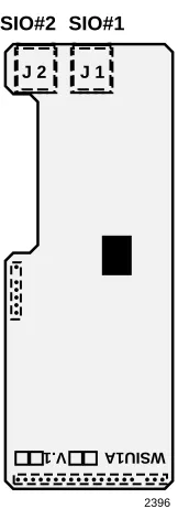
WSIU1 Installation
1. Make sure that the power supply switch is OFF. See
Figure 1-14.
2. Slide the front edge under the System Frame Ground Bar. Align and insert WSIU connector J4 into the
motherboard connector J21, and J3 into J20. Apply firm, even pressure to ensure proper making of the connectors. Make sure the edge of the WSIU is next to the connector J1 and J2.
3. Remove the “knock-out” from the KSU cover SI01 or SI02 access slot, and store the “knock-out” in the slots provided in the KSU base. (See Figure 1-11.)
WSIU Programming
Program 03: No assignment is necessary. WSIU1 is automatically enabled when installed and power is turned ON. It is not assigned to a slot.
Program 76-1X-Y: Assigns each installed WSIU1 port to a function. Where X identifies the WSIU1 port number (1~2) and Y identifies the WSIU1 port function:
♦ Y=1, RS-232 TTY (Program 77-1, LED 14 OFF)
♦ Y=2, SMDR
♦ Y=4, SMDI
♦ Y=6, Caller ID Interface
♦ Y=0, No function - this should be used for any WSIU1 ports that are not used.
Program 76-2X-Z: Assigns each installed WSIU1 port to operate at a specified transmission rate. Where X identifies the WSIU1 Port number (1, 2). Z identifies the WSIU1/port transmission rate in bits-per-second (bps):
♦ Z=1; 9600 ♦ Z=2; 4800 ♦ Z=3; 2400 ♦ Z=4; 1200
Note The sum of WSIU1 port 1 and port 2 bps rate cannot exceed 9600 bps.
WSIU Wiring
Note Refer to Chapter 10 – Peripheral Installation, SMDR and TTY for WSIU wiring/ interconnecting details. See Figure 1-18 for Caller ID interface box to WSIU wiring.
2396 WSIU1A V.1
J 1 J 2
SIO#1 SIO#2
DK8/DK14 Compatibility
DK14 Insta
lla
tion
DK8/DK14 Compatibility
Generally, Strata DK components are upward compatible to make upgrading cost-effective. Furthermore, there is a lot of cross-compatibility between similar systems. Most of the PCBs that were introduced for the DK14 can also be used in the DK8 system (see Table 1-2). Also, a number of DK8 PCBs can be used in the DK14 (see Table 1-3).
Table 1-2 DK14 PCBs Compatible with the DK8 System
Table 1-3 DK8 PCBs Compatible with the DK14 System DK14 PCBs Compatibility
(Use in DK8) Standard Optional Function
DKSU14A - X Base Unit
QMAU2A NO X Common Control/2-Loop Start CO Lines and 4-Digital Telephones Interface Unit
QPSU8A2 YES X Power Supply
QCDU2A YES X 1-Loop Start CO Line and 2-Digital Telephones Interface Unit
QRCU3A YES X 3-DTMF/ABR Tone Detection Receiver Unit QSTU2A YES X 2-Standard Telephones Interface Unit WSIU1A NO X 2-Serial I/O Interface Unit
QKYS1A YES X Auto Attendant Feature Key
DK8 PCBs Compatibility
(Use in DK14) Standard Optional Function
DKSU8A - X Base Unit
QMAU1A NO X Common Control/2-Loop Start CO Lines and 4-Digital Telephones Interface Unit
QCNU1A NO X Conference IC Unit QPSU8A YES X Power Supply
QCDU1A NO X 1-Loop Start CO Line and 2-Digital Telephones Interface Unit
QRCU2A/1A NO X 3-DTMF/ABR Tone Detection Receiver Unit QSTU1A NO X 2-Standard Telephones Interface Unit QSMU1A NO X 1-SMDR/TTY Interface Unit
DK14 Secondary Protection
DK14 Secondary Protection
The following diagram (see Figure 1-15) shows where secondary protectors must be installed for outside wiring. , , , , , , , , ,,, ,,, ,, , , , , , , , ,,, ,,, , , , , , , , ,,,, ,,,, ,, , , , , , ,,,, ,,,, , QSTU2
Building #1 Building #2
DK14 KSU Base Unit and QCDU2 HESB (optional) Digital Telephone or Cordless Base Standard Telephone or Other Device MDFB CO Line Earth Ground Earth Ground Secondary protectors DDCB DK14 KSU Base Unit and QCDU2 2422
Important! To protect against transient voltages and currents, solid state secondary protectors must be installed if there is outside wiring. These protectors, which contain fast semiconductors in addition to fuses, shall comply with the requirements for secondary protectors for communication circuits, UL497A.