ISSN (Print) : 2320 – 3765 ISSN (Online): 2278 – 8875
I
nternational
J
ournal of
A
dvanced
R
esearch in
E
lectrical,
E
lectronics and
I
nstrumentation
E
ngineering
(An ISO 3297: 2007 Certified Organization)
Vol. 3, Issue 8, August 2014
10.15662/ijareeie.2014.0308078
Copyright to IJAREEIE www.ijareeie.com 11457
Speed Control of Induction Motor Fed from
Wind Turbine Using Genetic Algorithm
Vineet Kumar Tiwari
1, Satyam Prakash
2, Abdul Zeeshan
3PG Student [PE&D], Dept. of Electrical Engineering, United College of Engineering & Research, Allahabad, India1.
Assistant Professor, Dept. of Electrical Engineering, United College Of Engineering & Research, Allahabad, India.2&3
ABSTRACT: This paper proposes a design of a speed control of three phase induction motor fed from wind turbine using genetic algorithm. The wind turbine acts as a prime-mover for doubly fed induction generator. To make the system stable, proper monitoring is required or sometimes an auxiliary system can also be a good option, which can support the primary system during undesirable conditions. The three phase induction motor has wide applications in industries due to its rugged construction, efficiency and low cost. Genetic algorithm is used for estimation of feedback controller parameters for three phase induction motor fed from wind turbine .Genetic algorithm offers certain advantages such as simple computational steps, derivative free optimization, reduced no. of iteration and assured near global optima. The simulation results show a significant enhancement in shortening development time and improving dynamic performance of the induction machine compared to the conventional speed control of induction motor drive.
KEYWORDS: Wind turbine, doubly fed induction generator, Genetic algorithm & three phase Induction motor.
I.INTRODUCTION
This study proposes the genetic algorithm for optimal designing of fuzzy controller for speed control of Induction
motor fed by wind turbine, which has a simple structure and robust performance in a wide range of operating
conditions. The use of induction motors has increased tremendously since the day of its invention. The reason for its day by day increasing popularity can be primarily attributed to its robust construction, simplicity in design and cost effectiveness. These have also proved to be more reliable than DC motors. However, the highly non-linear nature of the induction motor control dynamics demands strenuous control algorithms for the control of speed. The conventional controller types that are used for the aforementioned purpose may be numeric, neural or fuzzy. The controller types that are regularly used are: Proportional Integral (PI), Proportional Derivative (PD), Proportional Integral Derivative (PID), Fuzzy Logic Controller (FLC) or a blend between them.
Intelligent control methodologies are being applied to robotics and automation, communications, manufacturing, traffic control, to mention but a few application areas. The design problem of the proposed controller is formulated as an optimization problem and genetic algorithm is employed to search for optimal controller parameters. By minimizing the time domain objective function, in which the deviations in error between the reference and actual speed is involved,
speed control of Induction motoris improved.
II.INDIRECT FIELD ORIENTED CONTROL (IFOC)
Indirect vector control is very popular in industrial applications. The 𝑑𝑠− 𝑞𝑠 (direct and quadrature) axes are fixed on
the stator, but the 𝑑𝑟− 𝑞𝑟 axes, which are fixed on the rotor, are moving at speed 𝜔
𝑟 . Synchronously rotating axes
𝑑𝑒− 𝑞𝑒are rotating ahead of the 𝑑𝑟− 𝑞𝑟axes by the positive slip angle 𝜃
𝑠𝑙 corresponding to slip frequency𝜔𝑠𝑙. Since
the rotor pole is directed on the 𝑑𝑒 axis and synchronously rotating axes speed,
𝜔𝑒 = 𝜔𝑟+𝜔𝑠𝑙, (1)
ISSN (Print) : 2320 – 3765 ISSN (Online): 2278 – 8875
I
nternational
J
ournal of
A
dvanced
R
esearch in
E
lectrical,
E
lectronics and
I
nstrumentation
E
ngineering
(An ISO 3297: 2007 Certified Organization)
Vol. 3, Issue 8, August 2014
10.15662/ijareeie.2014.0308078
Copyright to IJAREEIE www.ijareeie.com 11458 𝛳𝑒 = ∫ 𝜔𝑒𝑑𝑡 = ∫ 𝜔𝑟+ 𝜔𝑠𝑙 𝑑𝑡 = 𝛳𝑟+ 𝛳𝑠𝑙 (2)
Where,
𝛳𝑒 =Angle between stator mmf relative to the rotor flux vector
𝛳𝑟= Angle between 𝑑𝑟− 𝑞𝑟 axes
𝛳𝑠𝑙= Slip angle, 𝛳𝑠𝑙 corresponding to slip frequency 𝜔𝑠
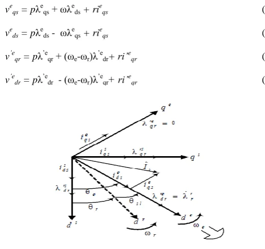
The phasor diagram suggests that for decoupling control, the stator flux component of current,𝑖𝑑𝑠 𝑒 should be aligned on
the 𝑑𝑒 axis, and the torque component of current, 𝑖
𝑞𝑠𝑒 should be on the 𝑞𝑒axis, as shown. For decoupling control, one
can make a derivation of control equations of indirect vector control with the help of d e – qe dynamic model of
induction machine (IM), Voltage equations are:
veqs = pλ
e
qs + ωλ
e ds + ri
e
qs (3)
veds = pλeds - ωλeqs + rieqs (4)
v’eqr = pλ
’e
qr + (ωe-ωr)λ ’e
dr+ ri’
e
qr (5)
v’edr = pλ’edr - (ωe-ωr)λ’eqr+ ri’eqr (6)
Fig. 1 Phasor Diagram explaining Indirect vector control
Torque developed by motor,
Teem = 3 2 𝑝 2(λ
’e qri
’e dr- λ
’e
dri ’e
qr) (7)
Where, λe
qs= Stator flux linkage along q-axis of d e – qe model, λeds= Stator flux linkage along d-axis of d e – qe model
λ’eqr= Rotor flux linkage along q-axis of d
e
– qe mode. λ’edr= Rotor flux linkage along d-axis of d
e
– qe model
ieqs = Stator current along q-axis of d e – qe model, i’eqr= Rotor current along q-axis of d e – qe model
i’edr= Rotor current along d-axis of d e – qe model, p = No. of poles
If de axis is aligned with the rotor field, the q-component of the rotor field, λ’eqr, in the chosen reference frame would be
zero,
λ’e
qr = Lm ieqs +L’ri’eqr =0 (8)
i’eqr = -𝐿𝑚
𝐿′𝑟i
e
ISSN (Print) : 2320 – 3765 ISSN (Online): 2278 – 8875
I
nternational
J
ournal of
A
dvanced
R
esearch in
E
lectrical,
E
lectronics and
I
nstrumentation
E
ngineering
(An ISO 3297: 2007 Certified Organization)
Vol. 3, Issue 8, August 2014
10.15662/ijareeie.2014.0308078
Copyright to IJAREEIE www.ijareeie.com 11459
With λ’eqr zero, the equation of the developed torque, reduces to
Tem = 3 2 𝑃 2 𝐿𝑚 𝐿′𝑟λ ’e
dri’eqs (10)
Where,
Lm = Magnetizing Inductance, 𝐿′𝑟= Rotor leakage Inductance
which shows that if the rotor flux linkage λ’edr is not disturbed, the torque can be independently controlled by adjusting
the stator q component current, ieqs.
For λ’eqr to remain unchanged at zero, its time derivative ( pλ’eqr ) must be zero,
λ’e dr =
𝑟′𝑟𝐿𝑚
𝑟′𝑟 + 𝐿′𝑟𝑝i
e
ds (11)
ωe
sl = ωe – ωr = 𝑟′𝑟 𝐿′𝑟
𝑖𝑒𝑞𝑠
𝑖𝑒𝑑𝑠 (12)
To implement the indirect vector control strategy, it is necessary to satisfy the above condition for proper
orientation. Torque can be controlled by regulating ieqsand slip speed ωsl. Given some desired level of rotor flux, λr*r,
the desired value of ie*ds may be obtained from,
λ’e* dr =
𝑟′𝑟𝐿𝑚
𝑟′𝑟 + 𝐿′𝑟𝑝i
e*
ds (13)
For the desired torque of T*em at the given level of rotor flux, the desired value of ie*qs
Tem = 3 2 𝑃 2 𝐿𝑚 𝐿′𝑟λ ’e
dri’eqs (14)
When the field is properly oriented, i’eqr is zero,
λ’e
dr= Lmieds: thus, the slip speed can be written as
ωe*
sl = ωe – ωr = 𝑟′𝑟 𝐿′𝑟
𝑖∗𝑒𝑞𝑠
𝑖∗𝑒𝑑𝑠 (15)
where, 𝑟′𝑟 = Rotor resistance
Thus, the above analysis shows that the vector control strategy can provide the same performance as is achieved from a separately excited DC machine; this is done by formulating the stator current phasor, in the two axis synchronously rotating reference frame, to have two components: magnetizing current component and torque producing current component; the generated motor torque is the product of two components. By keeping the magnetizing current component at a constant rated value, the motor torque is linearly proportional to the torque-producing component, which is quite similar to the control of a separately excited DC motor. An indirect field oriented control scheme for a current controlled PWM induction machine motor drive. The command values for the abc stator currents can then be computed as follows:
is*qs =ieqscosθe +iedssinθe (16)
is*ds = - ieqssinθe + iedscosθe (17)
i*as = is*qs (18)
i*bs = -(1/2)is*qs – ( 3/2) is*ds (19)
ISSN (Print) : 2320 – 3765 ISSN (Online): 2278 – 8875
I
nternational
J
ournal of
A
dvanced
R
esearch in
E
lectrical,
E
lectronics and
I
nstrumentation
E
ngineering
(An ISO 3297: 2007 Certified Organization)
Vol. 3, Issue 8, August 2014
10.15662/ijareeie.2014.0308078
Copyright to IJAREEIE www.ijareeie.com 11460
III. GENETIC ALGORITHMS
Genetic Algorithm (GA) is one of the optimization algorithms, which is invented to mimic some of the processes observed in natural evolution. The Genetic Algorithm is stochastic search techniques based on the mechanism of natural selection and natural genetics. Genetic Algorithm is employed to search for optimal controller parameters by
minimizing the time domain objective function. There are three main genetic operators named as reproduction,
crossover & mutation.
A.Rule Base Design For The Output (ΩSL):
The performance of the proposed technique has been evaluated with respect to the variation of load torque and speed wind turbine.
All the 9 If- Then Rules of the Rule Base used for the design of the Fuzzy Logic Controller are as follows:
1. If (error is NL) and (change in error is NL) then (change in control is A)
2. If (error is NL) and (change in error is ZE) then (change in control is A)
3. If (error is NL) and (change in error is PL) then (change in control is B)
4. If (error is ZE) and (change in error is NL) then (change in control is A)
5. If (error is ZE) and (change in error is ZE) then (change in control is B)
6. If (error is ZE) and (change in error is PL) then (change in control is C)
7. If (error is PL) and (change in error is NL) then (change in control is B)
8. If (error is PL) and (change in error is ZE) then (change in control is B)
9. If (error is PL) and (change in error is PL) then (change in control is C)
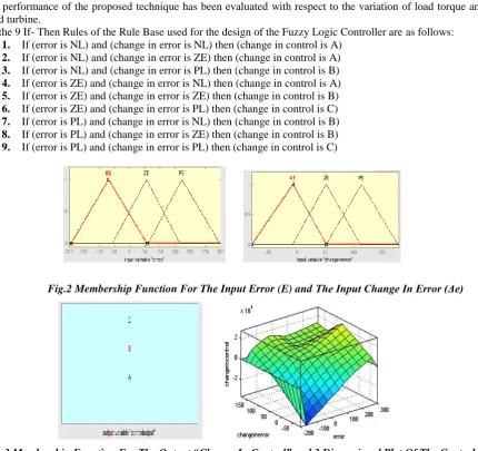
Fig.2 Membership Function For The Input Error (E) and The Input Change In Error (Δe)
Fig. 3 Membership Function For The Output “Change In Control” and 3 Dimensional Plot Of The Control Surface
The performance of the proposed controller has been evaluated by making above Membership Function For The Input
ISSN (Print) : 2320 – 3765 ISSN (Online): 2278 – 8875
I
nternational
J
ournal of
A
dvanced
R
esearch in
E
lectrical,
E
lectronics and
I
nstrumentation
E
ngineering
(An ISO 3297: 2007 Certified Organization)
Vol. 3, Issue 8, August 2014
10.15662/ijareeie.2014.0308078
Copyright to IJAREEIE www.ijareeie.com 11461 The various parameters for the GA based optimization toolbox are tabulated in Table 2.
Table 2.Values Of Parameters Used In Proposed Scheme
GA Property Value
No. of variable 1
Lower bound and upper bound 0 and 5
Max no. of generation 100
Cross-over probability 0.8
Mutation probability 0.1
Tolerance (10)-6
VI.WIND TURBINE MODEL
Wind energy is the kinetic energy that is of large masses of air moving over the earth’s surface. The blades of the wind turbine receive the kinetic energy, which is then transformed to the mechanical or electrical forms depending on end usage. The efficiency of converting wind energy to useful energy form depends on the efficiency with which
rotor interacts with the wind streams (Mihel-Popaet al,2004). The kinetic energy of a stream of air with mass m and
moving with velocity V is given as
E = 1
2𝑚𝑉
2 (21)
The kinetic energy of an air stream available for wind turbine having cross section area A and mass m that is
equal to ρ.ν and moving velocity Vw is given in
E = 1
2ρνVw
2 (22)
Where the ρ is the density of air and v is a volume of air portion available to the rotor. The power from the
wind is the kinetic energy on which the air is interacting with rotor per unit time has a cross section area A, can be
expressed as
Pw=
1 2ρAVw
3 (23)
V.MODELING OF DOUBLY FED INDUCTION GENERATOR BASED WIND TURBINE SYSTEM
The overall operation of Doubly Fed Induction Generator based wind turbine can be control by vector control method which was introduce in year of 1972 by a French scientist named as Black shalsh, this method introduce DC machine controlling technique means controlling on the behave of torque and speed of the 3 phase AC machine by conversion three phase to two axis quantities as direct axis quantities and quadeture axis quantities
Id Iq = 2
3
sin sin(− 2/3) sin(+ 2/3 cos cos (− 2/3) cos(+ 2/3)
Ia Ib Ic
(24)
All the quantities is taken in terms of direct axis quantities and quadeture axis quantities. As given in following equations values of stator voltages and rotor voltages in terms of direct axis and quadeture axis flux and direct axis and quadeture axis current with reactance and resistance of the same axis present in the machine.
ISSN (Print) : 2320 – 3765 ISSN (Online): 2278 – 8875
I
nternational
J
ournal of
A
dvanced
R
esearch in
E
lectrical,
E
lectronics and
I
nstrumentation
E
ngineering
(An ISO 3297: 2007 Certified Organization)
Vol. 3, Issue 8, August 2014
10.15662/ijareeie.2014.0308078
Copyright to IJAREEIE www.ijareeie.com 11462 Stator Flux equations.
λqs=(Lls+Lm)iqs+Lmiqr (25)
λds=(Lls+Lm)ids+Lmidr
Rotor Flux equations
λqr=(Llr+Lm)iqr+Lmiqs (26)
λdr= (Llr+ Lm)idr+ Lmids
VI. GA-MULTI OBJECTIVE OPTIMAL CONTROL WITH DFIG
The problem of adjusting the controller’s gains of the rotor-side DFIG converter, considering a specific operating point, may be formulated as a multi-objective optimization problem .The objectives to be optimized are the absolute errors between the rotor reference currents, which are established by the GA-fuzzy controllers, and the rotor measured
currents along the q and d axis respectively and the magnitude of the rotor voltage. By considering the DFIG vector
control formulation, it can be shown that the q and d components of the rotor current are very effective in controlling
both the DFIG stator active power and the terminal voltage respectively. This way, improving the rotor current dynamic response (which may be obtained by minimizing the error between the rotor reference and measured currents) may reflect also in a better dynamic performance for the DFIG stator active power and terminal voltage. Besides that, the minimization of an additional term in the objective function that will be responsible for obtaining optimized responses for the magnitude of the rotor voltage may improve the dynamic behavior of other variables which are controlled by the grid side converter, as for example the rotor active power which is a function of the rotor voltage, as well as the dc-link voltage, and the current and reactive power of the grid-side converter.
Fig.7 Block Diagram of speed control of Induction Motor fed from wind turbine using GA
This way the global objective is to improve the DFIG dynamic behavior after the occurrence of faults in the electrical network enhancing the ride-through capability, voltage control, and also increasing the small-signal and transient stability margins of the power system. A measure that indicates if a good adjustment for the parameters of the rotor side converter has been achieved is given by the fitness function which is composed by the weighted sum of three objectives which will be minimized by the genetic algorithm optimization procedure:
_ tsim _ _ _ _
F=∫0{ω1|idrref–idr|+ω2|iqrref−iqr|+ω3 𝑉𝑑𝑟2 𝑉𝑑𝑟2 + 𝑉𝑞𝑟2 dt (31)
Where ω1,ω2 and ω3are weight factors. The gains obtained by the pole placement technique as described in
ISSN (Print) : 2320 – 3765 ISSN (Online): 2278 – 8875
I
nternational
J
ournal of
A
dvanced
R
esearch in
E
lectrical,
E
lectronics and
I
nstrumentation
E
ngineering
(An ISO 3297: 2007 Certified Organization)
Vol. 3, Issue 8, August 2014
10.15662/ijareeie.2014.0308078
Copyright to IJAREEIE www.ijareeie.com 11463 III. RESULTS & DISCUSSIONS
In this section different comparative cases are examined to show the effectiveness of the proposed Genetic Algorithm based optimization of speed controller for induction motor fed from wind turbine. The Fuzzy-PI controller block is then upgraded by Genetic Algorithm based optimization. In order to verify the validity of the proposed GA with & without wind turbine, several simulations are carried out using MATLAB and Simulink software.
Fig. 10 Comparison Speed Vs Time Response
Fig. 10 presents the Comparison Speed Vs Time Response between conventional PI, Fuzzy-PI&GA-fuzzy-PI controller For Constant Load Torque 5 N-m and Variable Speed (50 rad/sec , 100rad/sec and 80 rad/sec at sample time 0 sec, 1 sec and 3 sec respt.)
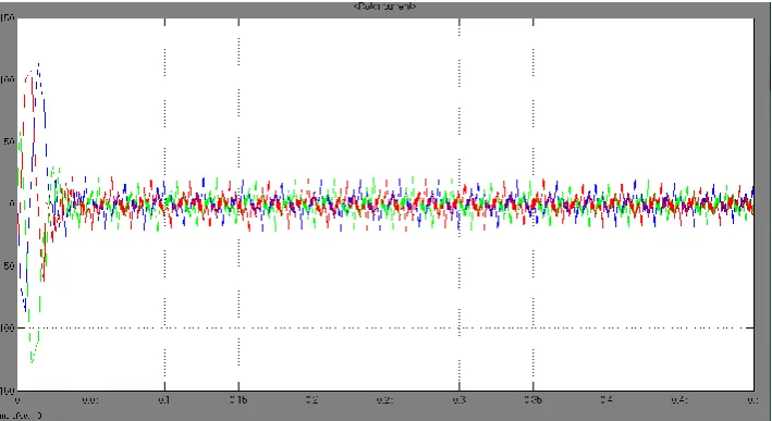
Fig. 11 Rotor Current vs Time Response for GA-Fuzzy PI Controllers Only
ISSN (Print) : 2320 – 3765 ISSN (Online): 2278 – 8875
I
nternational
J
ournal of
A
dvanced
R
esearch in
E
lectrical,
E
lectronics and
I
nstrumentation
E
ngineering
(An ISO 3297: 2007 Certified Organization)
Vol. 3, Issue 8, August 2014
10.15662/ijareeie.2014.0308078
Copyright to IJAREEIE www.ijareeie.com 11464 Fig. 12 Rotor Current vs Time Response for GA-Fuzzy PI Controllers With wind turbine
It is noticed in Fig. 11 & fig. 12 that when using the optimal gains of the GA-Fuzzy PI Controllers with wind turbine,
the rotor current presents a better time response when compared without using a wind turbine.
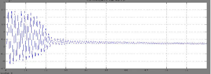
Fig. 13 Electromagnetic Torque Vs Time Plot for GA Fuzzy PI Controllers only
Above result shows plot of Electromagnetic Torque Vs Time Plot for GA Fuzzy PI Controllers only without use of wind turbine.
ISSN (Print) : 2320 – 3765 ISSN (Online): 2278 – 8875
I
nternational
J
ournal of
A
dvanced
R
esearch in
E
lectrical,
E
lectronics and
I
nstrumentation
E
ngineering
(An ISO 3297: 2007 Certified Organization)
Vol. 3, Issue 8, August 2014
10.15662/ijareeie.2014.0308078
Copyright to IJAREEIE www.ijareeie.com 11465
Fig. 13 & fig. 14 show that when using the optimal gains of the GA-Fuzzy PI Controllers with wind turbine, the
Electromagnetic Torque Vs Time Plot presents a better time response when compared a system without using a wind turbine.
VII. CONCLUSION
By minimizing the time domain objective function, in which the difference between the reference and actual speed are involved; speed control of IM motor is improved. Simulation results emphasis that the designed GA tuning fuzzy- PI controller is robust in its operation and gives a superb performance for the change in load.
In this paper, the advantages of the GA-Fuzzy-PI Controller with wind turbine used in the simulation are as follows:
1. The Rise Time is reduced by 98%
2. The Settling Time is reduced by 78.5%
3. The Maximum Overshoot was reduced by 68.5%
The above results clearly indicates that a three phase induction motor fed from wind turbine using Genetic Algorithm based tuning of the Fuzzy-PI controller gives improved electromagnetic torque, rotor current & better speed performance which results a robust controlled system. The controller helps the induction motor to track speeds both above and below its base speed.
REFERENCES
[1] Mishra Amit and Zaheeruddin “Design of Speed Controller for Squirrel-cage Induction Motor using Fuzzy logic based Techniques”
International Journal of Computer Applications (0975 -8887) Volume 58 - No. 22, November 2012
[2] Ouiguini R., Djeffal K., Oussedik A. and Megartsi R., “Speed Control of an Induction Motor using the Fuzzy logic approach.”, ISIE’97 - Guimariies, Portugal, IEEE Catalog Number: 97TH8280, vol.3, pg. 1168 – 1172.
[3] Dr. Rami A. Mahir, Dr. Ahmed Ziad M., Mr. Amjad J. H. “Indirect Field Orientation Control of Induction Machine with Detuning Effect”, Eng.&Tech..Vol.26.No 1,2008.
[4] Pavol Fedor and Daniela Perduková, “A Simple Fuzzy Controller Structure,” Acta Electrotechnica et Informatica No. 4, Vol. 5, pp. 1-4, 2005.
[5] Abdullah I. Al-Odienat, Ayman A. Al-Lawama, “The Advantages of PID Fuzzy Controllers Over The Conventional Types,” American Journal of Applied Sciences 5 (6): 653-658, 2008, ISSN 1546-9239, pp. 653 – 658.
[6] Brian Heber,LongyaXu, Yifan Tang “Fuzzy Logic Enhanced Speed Control of an Indirect Field Oriented Induction Machine Drive” IEEE.
[7] Pengfei Guo Xuezhi Wang Yingshi Han “The Enhanced Genetic Algorithms for the Optimization Design” 978-1-4244-6498-2
[8] João P. A. Vieira, Marcus V. A. Nunes and Ubiratan H. Bezerra “Using Genetic Algorithm to Obtain Optimal Controllers for the DFIG
Converters to EnhancePower System Operational Security” ISBN: 978-953-307-221-0.