ISSN 2348 – 7968
843
Cyclic Channel Coding algorithm for Original and
Received Voice Signal at 8 KHz using BER
performance through Additive White Gaussian Noise
Channel
Ali Tariq Bhatti
North Carolina A&T State University,
Greensboro, NC USA
[email protected], [email protected]
Abstract
Digital communication systems are becoming increasingly attractive because of the ever-growing demand for data communication and because digital transmission offers data processing options and flexibilities not available with analog transmission [1]. The solution to any communication problem can be achieved either one of two ways i.e. by hardware logic or software where it is relatively easier and flexible in terms of reconfiguration. In data communication, channel coding is designed to improve communication by enabling the transmitted signals to better with-stand the effects of various channel impairments such as noise, interference, and fading. In this paper, Cyclic Coding technique is aimed to perform that there exist an empirical realization of the theoretical concept of error reduction vs. bandwidth. With this technique, acquire audio voice signal with 8 bits resolution and 8 kHz sampling frequency for 5 seconds. The recording voice is in ‘.wav’ format to acquired voice signal that must have sufficient amplitude without clipping it to allow one listen to the voice clearly when played. The recorded voice signal of .wav file was also then read by MATLAB for further processing. Sampled the signal by 8 KHz sampling frequency, quantize using
8-bit μ-law companding on-uniform quantizer, and
modulate the signal by Binary phase shift keying.Bit Error Rate performance plot is evaluated for the
coded and un-coded version of the voice signal and
needed to save the voice output from the simulated
receiver in a .wav file. At the last, cyclic coding
algorithm will make a comparison of the original and received voice signals via playing back both signals.
1. Introduction
.
Cyclic coding algorithm is an error correction algorithm to be implemented on receiver side to decode the messages properly. This transmission scheme is said to be a Forward Error Correction (FEC) [8]. An error correcting code consists of techniques and algorithms and has two fundamental operations: encoding and decoding [9]. In channel coding, however; such channels extreme fading of the signal amplitude occurs and Inter Symbol Interference (ISI) due to the frequency selectivity of the channel appears at the receiver side [2]. Cyclic codes are linear
block error-correcting codes performed to have convenient algebraic structures for efficient error detection and correction. In this paper, it is required to acquire audio voice signal with 8 bits resolution and 8 kHz sampling frequency for 5 seconds. In 5 seconds, audio voice signal indicated as for e.g. “This is my research
journal paper. My name is Ali Tariq Bhatti.
ISSN 2348 – 7968
844
paper, record the audio voice in ‘.wav’ format, soacquired original voice signal must have sufficient amplitude without clipping it to allow one listen to the voice clearly when played. The recorded original voice signal of .wav file was then read by MATLAB for further processing. Implement the cyclic code using Additive White
Gaussian Noise (AWGN) channel to perform
the recorded original voice signal to be read, simulated, transmitted and received. It is commonly used to simulate background noise of the channel in addition to multipath, terrain blocking, interference, ground clutter and self-interference that modern radio systems encounter in terrestrial operation [3]. It is a channel model which affects the communication system with linearly addition of white noise with a constant spectral density. This model does not account for fading, multipath, dispersion. [5]. However, this memory-less AWGN channel shows noise on
each of the transmitted symbol independently. Therefore, sampled the signal by 8 KHz sampling frequency, quantize using 8-bit μ-law companding on-uniform quantizer, and modulate the signal by Binary phase shift keying
(BPSK). BPSK is the modulation achieved by
as system bandwidth isn’t a constraint. The
standard deviation of this AWGN is considered
to be 0.8. The AWGN channel model fails to accurately describe the dominant sources of noise in such channels. While Turbo decoders for fading channels has been described in [6], power consumption issues have not been addressed. In addition, cyclic channel coding
verifies the performance of by playing the original and the received voice signals. Bit Error Rate (BER) performance plot is evaluated for the
coded and un-coded version of the voice signal and also needed to save the voice output from the simulated receiver in a .wav file. At the last, verify by making a comparison of the original and received voice signals via playing back both signals, and then compute Mean Square Error (MSE). The strategy proposed in [4] is to minimize the MSE between the original and received (reconstructed) signals. Finally the solution to the problem can be classified from the following points of view.
1) In this paper, the noise is mixed to the audio voice through (AWGN).
2) Encoding scheme employed as Cyclic Block Coding algorithm
3) Binary PSK(Phase Shift Keying) is the modulated and demodulated scheme selection 4) Computing bit error rate (BER)
5) Performance plot of original transmitted signal and received signal, and compute MSE.
2.
METHODOLOGY AND
SELECTION OF DESIGN
FACTORS
2.1
Flow-chart Design & Description
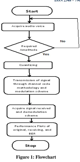
Figure 1 shows the flowchart of the cyclic coding algorithm for this problem, annotated with all possible design factors at each level of the process flow.
Flow-chart starts.
Acquired original audio voice in .wav format A good and required sampling rate of 8 KHz
ISSN 2348 – 7968
845
equivalent to 40000 sampled data points enoughto represent the analog signal. “No” indicates in the flowchart, if required or sufficient amplitude is not given..
Then, when it gets the required or sufficient amplitude, sampled the signal by 8 KHz sampling frequency, quantize using 8-bit μ-law companding on uniform quantizer. This quantizer uses the pulse code modulation (PCM) to map the analog amplitudes of the voice signal into code numbers ranging from 0 through 28-1
since 8 bits resolution is used. The scheme for quantization is importantly based on signal strength. Audio voice signal is perturbed by AWGN, however; non-uniform quantization is ideal as it provided fine quantization before modulation and subsequent transmission. The modulation scheme for original transmitted
signal by its system bandwidth used is BPSK of Cyclic coding methodology. For zero ISI, symbol rate should be less or equaled to twice
the bandwidth ( ) of entire system
comprising transmitter, channel and receiver. Then in second last step of flow-chart,
demodulated the receive signal and computed the BER.
Finally, in the last step of flow-chart, ,get the analog value of each code number, the mean of the extreme ends between which the code number falls is computed, The main aim is to plot the performance of original transmitted voice and receive voice signal, and also BER. Then compute MSE too.
Flow-chart stops.
Figure 1: Flowchart
2.2
Block Diagram
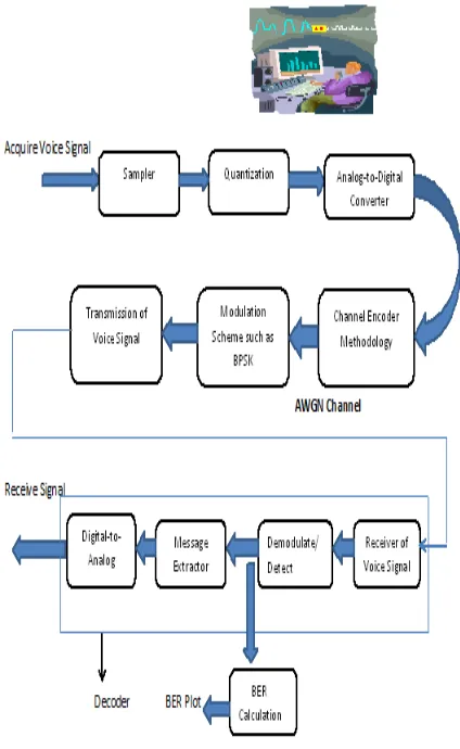
The block diagram in figure 2 can be explained:
1) Sampler: It collects and samples the voice
signal at 8 KHz to be sampled
with 8 bit resolution. The acquired original voice signal recorded for 5 seconds equal to 40000 sample points exist with various magnitudes. Moreover, voice signal (normally about 3.4 KHz), however; this frequency was enough to meet the Nyquist Criterion for selecting the sampling frequency. Nyquist criterion state that:
Where B is the bandwidth of the signal and is
ISSN 2348 – 7968
846
acquired original voice signal is converted todiscrete time-continuous value signal.
2) Quantization: The continuous time signal of
original voice signal is converted to a discrete time-discrete value signal. Index of corresponding quantized level is encoded as binary digits. In this case, 8-bits were chosen which gave fine resolution. Quantization step is
generally calculated as
Pulse Code Modulation prior to band-pass signaling used to map the analog amplitudes of the voice signal into code numbers ranging from 0 through 28-1 since 8 bits resolution. It formed
the quantization levels prior to the mapping.
3) Analog-to-Digital Converter:
This converter converted to change the code numbers to binary messages; each of length 8 i.e. k=8.
4) Channel Encoder Methodology:
The chancel encoder methodology scheme used is cyclic coding. However, in this paper, this code forms the code-word for each message after which the code-words are transmitted.
5) Modulation scheme such as BPSK:
Modulation such as BPSK is used to perform
taking bits at a time, where k is given by:
In this paper, M=2 which is number of bits per symbol. This modulation is the most robust of all the PSKs since it takes serious distortion to make the demodulator reach an incorrect decision. It is, however, only able to modulate at 1 bit/symbol, so is unsuitable for high data-rate applications when bandwidth is limited [10].
6) Transmission of voice signal:
The transmission of original acquired voice signal transmitted the code-words over the AWGN (Additive White Gaussian Noise) channel.
7) Receiver of voice signal:
At receiver end, it receives the transmitted code-words with the added AWGN and routes data to the error correction mechanism.
8) BER Calculation:
Calculate BER and the plot of BER is obtained by iterating through a list of arbitrary signal-to-noise ratio values.
9) Demodulate/Detect:
Error correction function is embedded in the decode block. Therefore, it detects and corrects errors based on its error detecting and correcting capabilities.
10) Message Extractor:
In this block, cyclic code extracted the message parts of the corrected code-words.
11) Digital-to-Analog Converter:
This converter performed in three steps which is (a) Converts the extracted message to the code
number representations.
(b) Then, maps them to the quantized intervals. (c) Finally, to get from digital-to-analog signal of
ISSN 2348 – 7968
847
Figure 2: Block diagram
2.3
Selection of Design factors
Cyclic codes are a special case of linear codes if every cyclic shift of a code-word is a code-word. Cyclic codes have various advantages such as:
They are often used for error detection (CRC)
Used for packet networks
Used for Shift register encoders and syndrome units
Simple burst error correction (error trapping)
Random error correction by solving polynomial equations
The disadvantage of Cyclic coding lies in that even the syndrome lookup table method of error
correction is very cumbersome and complex, and is impractical for all but the shortest of code vectors [7].
Binary cyclic codes are also a subclass of linear block codes. The components of a code-word U = (u0, u1, u2, . . ., un-2, un-1) can be treated as the
coefficients of a polynomial U(X) as follows: [1] U(X)=u0+u1X+u2X2+....+un-1Xn-1
Expressing the code words in polynomial form, the cyclic nature of the code manifests itself in the following way. The generator polynomial g(x) for an (n, k) cyclic code is unique and is of the form [1].
g(X)=g0+g1X+g2X2+…+gpXP
Therefore, the message polynomial m(X) is m(X)=m0+m1X+m2X2+…+mn-p-1Xn-p-1
As, p=n-k. Every code-word polynomial in the (n, k) cyclic code can be expressed as
U(X)=(m0+m1X+m2X2+…+mk-1Xk-1)* g(X)
Remainder p(X) can be expressed as: P(X)=p0+p1X+p2X2+…+pn-k-1Xn-k-1
So, finally
P(X)+Xn-km(X)=q(X)g(X)=U(X)
The code-word polynomial for the cyclic code corresponds to the code vectors as:
U=(p0, p1,… pn-k-1, m0, m1,… mk-1)……(1) (n-k) parity bits k message bits
“U” is said to be valid code-word of the subspace, if g(X) divides into U(X) without a remainder.
The number of parity bits and code capability using the standard array for estimating the code capability is as:
Number of parity bits:
n-k≥ log2[1 + + ]...(2)
ISSN 2348 – 7968
848
The error-detection capability of a code isdefined in terms of the minimum Hamming
distance of the code, as:
– 1…(3) In general, the error-correcting capability “t” of a code is defined as the maximum number of guaranteed correctable error per code-word and is written [1]
2t+1…...(5) In designing an (n, k) linear block code, upper bound on the t-bit error correction capability and bound, known as the Plotkin bound, is given by
In general, a linear (n, k) code must meet all upper bounds involving error-correction capability (or minimum distance). For high-rate codes, if the Hamming bound is met, then the Plotkin bound will also be met [1]. From equation (5) and equation (6), n is computed as:
To design a perfect code, the following constraint has to be met which is below:
Since the audio original voice signal is sampled with 8 bits resolution, the message length, k is assumed to be 8, thus t = 2, and k = 8. In this paper the implementation and designed part is to correct up to 2 bits errors. In addition, the cyclic coding algorithm has to be a perfect code. According to the design selection, equation (4) guarantees that the code corrects all errors up to t
bits errors which make the code a perfect code.
As a result, MATLAB code implementation is used to find the various “n” from equation (7)
for certain values of t as it shows in table 1 too
under the Results. Therefore, ‘n’ is lower
bounded and is upper bounded.
Consequently, to correct up to 2 bits error, the
minimum code-word length to be selected has to be 11 since choosing a higher value for n
decreases the code rate (i.e. k/n). From table 2, it is obvious that to practicallycorrect up to 2 bits errors, the code-word length has to be 17 instead
of 11 otherwise the practical implementation
corrects only 1 bit error. So, I am using (17, 8) code.
2.4 Perfect Code
The code is therefore a (17, 8). The number of
n-tuples is , the number of code-words is ,
and the number of cosset leaders is . Thus the
standard array size is x . From equation (8) the total number of errors that can be corrected
as =154. This is less than
and that the code can practically correct up to all 2 bit error patterns. Hence, the (17, 8) is a perfect code.
3
EXPERIMENT PROCEDURE
AND RESULTS
3.1
Experimental Procedure
ISSN 2348 – 7968
849
The minimum (minimumV) and themaximum (maximumV) amplitudes of the signals are obtained in MATLAB code. Using these values, quantization increment.
is computed as follows:
. Using Pulse
Code Modulation, the quantization intervals are formed as follows: minimumV,
minimumV+ , minimumV+ ,
minimumV+3
…minimumV+(2qbits^k-1) maximum. The mean of any two consecutive values forms the quantization level. The intervals are numbered integrally from 0 through 2^k-1 to form the code numbers. Moreover, the assigned code numbers are converted to binary strings of length k to form the message known as
PCM sequence.
Parity strings are generated and left-appended to the messages to form the code-word using Cyclic Code techniques. This gives a code-word of length n (i.e. 17).
Binary Phase Shift Keying is modulated for Coded signal taking one bits at a time. The original voice signal is then transmitted
through an additive white Gaussian noise channel.
Modulated signal is demodulated to obtain bit stream array at receiver end.
An error correction mechanism is implemented to detect and correct the errors caused by the additive white Gaussian noise. The message part is then extracted and
converted back to the code numbers.
The corresponding quantization level is assigned to each of the numbers to form the quantized sample values.
These coded values then form the received signal.
The received signal is then played back through speaker device.
3.2 Results
MATLAB code implementation using code-word lengths for various error detecting and correcting capabilities are shown in the following table 1 and table 2. Table 1 shows the
upper bound of detectable errors, the upper bound correctable error, t and the lower bound of
the code-word length, n.
3 5 7 9 11
t 1 2 3 4 5
n 8 11 14 17 20
Table1
2 4 4
6
3
t 0 1 1
2
1
n 8 11 14
17
20
Table 2
Table 2 showing the implemented actual number
of detectable errors, and actual correctable error, tfor various values of n.
In this paper, MATLAB coding implementation used in table 2 has to correct two error patterns. In fact, actual implementation can correct just 1 bit error for n = 11. As a result, in order to
practically correct up to 2 bits errors as desired, the code has to be a (17, 8) code. Hence,
ISSN 2348 – 7968
850
4.
Discussion and Performance
Analysis
From table 1, error detecting capability, increases, and then the error correcting capability and the code-word length also increase. In short,
error detecting capability is directly proportional to error correcting capability and the code-word length.
In order to actually correct up to 2 bits errors, the code has to be a (17, 8) code. However, it also
requires more computational time and more computer memory since the code rate is smaller compared to that of table 1i.e. the (11, 8) code. The plots of Original and Receive voice signal appear to be replica of each other. As per the analysis from Original and Receive voice signal plot, the full error correction of transmitted signal was not achieved since the bit array difference between original voice signal and received voice signal is not null signifying. As a result, difference shows that there were more than two errors to be corrected, thus the received voice signal was not approximately the same as original voice signal due to high distortions because the high variance of noise added to original transmitted voice signal.
0 1 2 3 4 5 6 7 8 9 10 10-6
10-5 10-4 10-3 10-2 10-1
Eb/No in (db)
Bi
t Er
ro
r
R
a
te
(
BER
)
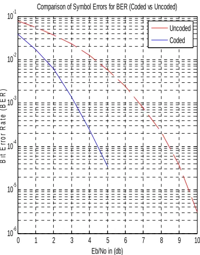
Comparison of Symbol Errors for BER (Coded vs Uncoded)
Uncoded Coded
Figure 3: BER Performance plot
Figure 3 shows the two curves of BER plot, implemented one for the modulation scheme without channel coding (Red Broken line) and another with the same modulation with coding (Solid Blue line). As a result for calculating the BER in MATLAB implementation, the analysis of the BER plot from figure 3 of un-coded to coded message showed a significant improvement comparatively. Therefore, significant improvement performance of BER plot is seen for coded message as compared to un-coded message.
To ascertain the performance of the code, MSE is computed for i=1 to 40000 sample points for
the Original and Received Signal voice as:
MSE=
ISSN 2348 – 7968
851
Original and Received Voice Signals
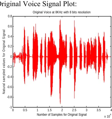
Original Voice Signal Plot:
0 0.5 1 1.5 2 2.5 3 3.5 4
x 104 -1 -0.8 -0.6 -0.4 -0.2 0 0.2 0.4 0.6 0.8
Original Voice at 8KHz with 8 bits resolution
Number of Samples for Original Signal
N a tur a l s a m p le d v a lu es for O ri g in al S ign al
Figure 4: Original Voice Signal
Received Voice Signal Plot:
0 0.5 1 1.5 2 2.5 3 3.5 4
x 104 -1 -0.8 -0.6 -0.4 -0.2 0 0.2 0.4 0.6 0.8
Received Voice signal at 8KHz with 8 bits resolution
Number of Samples for Received Signal
Q uan ti z e d s a m p le d v a lu e s f o r R e c e iv ed S igna l
Figure 5: Receive Voice Signal
5.
CONCLUSION
Finally, the impact analysis from Cyclic coding algorithm for voice signal of 5 seconds using (17,8) indicates that
1) Cyclic Channel coding algorithm is essential for improving signal to noise ratio to reduce bit error rate.
2) Bit Error performance is inversely proportional to the signal to noise ratio. 3) Compression of signal before uniform
quantization was not employed for the requirement.
4) Error-correction coding gives different system trade-offs such as Error Performance versus Bandwidth, Power versus Bandwidth, Coding gain, Data Rate versus Bandwidth, and Capacity versus Bandwidth.
5) Cyclic Code reduces the effect of error on transmitted signal caused by AWGN channel.
6. Reference
[1] Sklar B. “Digital Communications 2nd Edition”, 2001.
[2] Mohammaed Slim Alouini and Andrea J. Goldsmith, ‘Capacity of Rayleigh fading channels under different Adaptive Transmission and Diversity combining Techniques’, IEEE Transactions on Vehicular Technology, Vol. 48, No. 4, pp. 1165-1181, July 1999.
[3] Syed Md. Asif, Abdullah - Al - Maruf, S. Anisul Islam, amitavo Tikader,Md. Abdul Alim” Comparison Of Ber Between Uncoded Signal And Coded Signal (Using Convolution Code) Over Slow Rayleigh Fading Channel”, © 2005-2009JATIT,pp.76-82.
[4] F. O. Huck, C. L. Fales, N. Halyo, R. W. Samms, and K. Stacy, “Image gathering and processing—Information and fidelity,” Opt. Soc. Amer. J. A: Opt. Image Sci., vol. 2, pp. 1644– 1666, 1985.
ISSN 2348 – 7968
852
[6] E. K. Hall and S. G. Wilson, “Design andanalysis of turbo codes on Rayleigh fading channels,” IEEE J. Select. Areas Commun., vol. 16, pp. 160–174, Feb. 1998.
[7] Dr. Alex Grant, ECC 1550 Homepage, http://www.itr.unisa.edu.au/~alex/ECC
[8] Lin and Daniel J Costello (1983) Error control coding: fundamentals and applications. Englewood Cliffs, Prentice Hall, NJ.
[9] Moreira JC and Farrell PG (2006) Essentials of error-control coding. John Wiley & Sons, England.
[10] G. Maral and M. Bousquet, “Satellite Communication System (System Technique and Technology)”, 4th Edition, John Wiley & Sons, 2002.