V/F Speed Control of an Induction Motor
Drive Fed by Switched Boost Inverter
Riya Elizabeth Jose
1, Maheswaran K.
2PG Student [PED], Dept. of EEE, Pampady. Nehru College of Engineering and Research Centre, Kerala, India1 Assistant Professor, Dept. of EEE, Pampady. Nehru College of Engineering and Research Centre, Kerala, India2
ABSTRACT:Induction motor characteristics are well suited for adjustable or variable speed drive than constant speed drives because of its low maintenance cost, self starting, simple and rugged construction, multiple methods for obtaining smooth torque-speed control as per the requirement and suitability of the industrial application. Conventional Z-source converter (ZSC) employs a unique impedance network consisting of two inductors and two capacitors of equal inductance and capacitance which is difficult to realize in practice. Switched boost converter (SBC) is an improved derivative of ZSC comprising of one inductor and one capacitor which overcomes the stability issues associated with it. This converter can supply both DC and AC loads. The speed control of an induction motor is a necessity because it ensures smooth operation and provides torque control. The variable voltage-variable frequency (V/F) speed control of a three phase induction motor that is fed by a switched boost inverter (SBI) is introduced. The Pulse Width Modulation (PWM) control strategy for three phase switched boost inverter is also introduced. The performance analysis of three phase induction motor fed by switched boost inverter in terms of speed and electromagnetic torque is simulated using MATLAB software.
KEYWORDS: Constant V/F control, Induction motor, PWM scheme, Voltage Source Inverter
.
I.INTRODUCTION
Motion control is required in large number of industrial and domestic applications like transportation systems, rolling mills, paper mills, paper machines, textile mills, machine tools, fans, pumps, robots, washing machines etc. Systems employed for motion control are called drives and may employ any of the prime movers such as diesel or petrol engines, gas or steam turbines, steam engines, hydraulic motors and electrical motors, for supplying mechanical energy for motion control. Drives employing electric motors are known as electric drives.
Induction Motors are one of the most widely used motors in the world due to which it is termed as “Workhorse of the Industry”. It is used in transportation and industries, and also in household appliances, and laboratories. For industrial control and automation, three phase induction motors are most widely used. When power is supplied to an induction motor with specified voltage and frequency, it runs at its rated speed. However many applications need variable speed variations to improve the quality of the product. The developments in power electronics and semiconductor technology have led to the improvement in power electronic systems. Three phase voltage-fed PWM inverters are recently showing growing popularity for multi-megawatt industrial drive applications. Variable voltage and frequency supply to is invariably obtained from three-phase voltage source inverter. But VSI has certain limitations. But VSI has certain limitations. A three phase VSI has six active states and two zero states. A zero state is produced when the upper three or lower three switches of a VSI are turned on at the same time, shorting the output terminals. The upper and lower two switches of any phase leg can never be turned on at the same time which might result in a problem called a shoot-through short circuit. The shoot-shoot-through state is a forbidden state for a traditional VSI as it destroys the inverter.
called switched boost inverter (SBI) is an improved derivative of ZSI which exhibits similar advantages of ZSI with lower number of passive components and more active components compared to ZSI.
This paper presents a power converter called switched boost inverter (SBI) to drive a three phase induction motor. It is often required to control the output voltage of inverter for the constant voltage/frequency (V/F) control of an induction motor. PWM (Pulse Width Modulation) based firing of inverter provides the best constant V/F control of an induction motor. Amongst the various PWM techniques, the sinusoidal PWM is good enough and most popular that provides smooth changeover of V/F, four quadrant operation, harmonic elimination, etc in both closed and open loop applications. Three phase induction motors are reliable, robust, and highly durable and of course need less maintenance.
Rest of the paper is organized as follows. Section II presents the V/F control of induction motor fed by SBI. PWM control strategy of the converter is described in Section III. Simulation results are in given in section IV and paper is ended with a conclusion in section V.
II.LITERATURE SURVEY
Induction motors are the most widely used motors due to their reliability, low cost and robustness. Out of the several methods of speed control of an induction motor, constant V/F speed control method is most widely used due to its simplicity [1]. In this method, the V/F ratio is kept constant which in turn maintains the magnetizing flux constant so that the maximum torque remains unchanged [4]. Z Source inverter overcomes the shoot through short circuit problem of VSI. But ZSI has certain disadvantages which were overcome by switched boost inverter [3], [5]. Modified pulse width modulation technique have been developed for a three phase switched boost inverter [2]. Simulation and analysis of V/F control of Induction motor have been studied [1].
III
.
V/F CONTROL OF INDUCTION MOTOR FED BY SBIIn recent year, researches are focused towards distributed power generation in order to meet the power crises. These distributed generation (DG) systems consists of different renewable energy sources such as solar, wind, fuel cell etc.
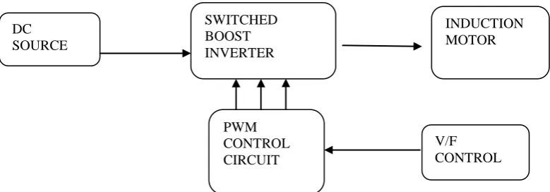
Fig.1: Block diagram of open V/F control of an induction motor fed by SBI
Figure 1 shows the block diagram representation of an induction motor that is fed by a switched boost inverter. The inverter input may be any renewable energy sources. Here, a dc source is considered. This switched boost inverter is then used to drive a three phase induction motor. The speed of the induction control is controlled by scalar method called V/F control method where the ratio of voltage to frequency has to be maintained constant thus maintaining the flux constant. By keeping the flux constant the maximum torque will be constant for varying speed. In order to maintain a constant V/F ratio, the output voltage of the inverter has to be controlled which is done by the PWM control circuit.
DC SOURCE
INDUCTION MOTOR SWITCHED
BOOST INVERTER
PWM CONTROL CIRCUIT
IV. STEADY STATE OPERATION OF SBI
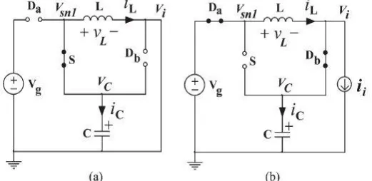
Switched boost converter (SBC) is able to buck or boost the input voltage in a single stage to get the desired output voltage. Fig.1 shows the schematic of a three phase SBI in which a switched boost network comprising of one active switch (S), two diodes (Da,Db), one inductor (L) and a capacitor (C) is connected between voltage source Vg and inverter bridge. Similar to ZSI, the SBI utilizes the shoot-through state of the H-bridge inverter (both switches in one leg of the inverter are turned on simultaneously) to boost the input voltage Vg to Vc.
To explain the steady-state operation of the SBI, assume that the inverter is in shoot-through zero state for duration D.TSin a switching cycle TS. The switch Sis also turned on during this interval. As shown in the equivalent circuit of
Fig. 2(a), the inverter bridge is represented by a short circuit during this interval. The diodes Da and Db are reverse biased(as VC >Vg), and the capacitor Ccharges the inductor Lthrough switch Sand the inverter bridge. The inductor
current in this interval equals the capacitor discharging current.
Fig.1. Schematic of three phase SBI
For the remaining duration in the switching cycle (1 − D).TS, the inverter is in non-shoot-through state, and the switch S
is turned off. The inverter bridge is represented by a current source in this interval as shown in the equivalent circuit of Fig.2(b). Now, the voltage source Vg and inductor L together will supply power to the inverter and the capacitor through diodes Da and Db. The inductor current in this interval equals the capacitor charging current added to the inverter input current. Note that the inductor current is assumed to be sufficient enough for the continuous conduction of diodes Daand Dbfor the entire interval (1 − D).TS.
Fig.2. (a) Equivalent circuit diagram of SBI during the interval DTs (b) Equivalent circuit diagram of SBI during the
Under steady-state, the average voltage across the inductor and the average current through the capacitor in one switching cycle should be zero. Using volt–second balance, we have
𝑉𝑐. 𝐷 + (𝑉𝑔− 𝑉𝑐). 1 − 𝐷 = 0
𝑉𝑐 𝑉𝑔
= (1 − 𝐷) (1 − 2𝐷)
The average dc link voltage Vican be calculated as
𝑉𝑖= 0. 𝐷 + 𝑉𝐶. 1 − 𝐷 = 𝑉𝐶. (1 − 𝐷)
The peak output AC line voltage is given by,
𝑉𝑜𝑚 = 𝑀𝑉𝐶
𝑉𝑜𝑚 =
1 − 𝐷 𝑀𝑉𝑔 (1 − 2𝑑)
It is observed from equation (3) and (5) that VC can be boosted and Vom can be bucked or boosted based on the
shoot-through duty ratio D and modulation index M.
V. PWM TECHNIQUE
As mentioned earlier, the SBI requires shoot-through state of the inverter bridge for its operation. Also there is an extra switch „S‟ which should be synchronized with the shoot-through state of the inverter bridge. So, the PWM control techniques of a VSI cannot be directly used to generate the gate control signals (GS, GS1, GS3, GS5, GS4, GS6, GS2) of the three-phase SBI.
This section describes a PWM control strategy suitable for the gate control signal generation of three-phase SBI. The technique is derived from the traditional unipolar sine-triangle PWM of three-phase VSI. The PWM strategy of the three-phase SBI involves the comparison of five modulation signals with a high frequency triangular carrier (vtri). Out
of these five modulation signals two are dc (−VST and +VST) signals, and three are sinusoidal (vma, vmb, vmc) signals
which are phase shifted by 120° from each other. Fig.3 depicts all the five modulation signals and the triangular carrier signal. The mathematical equations for vma, vmb, vmc, +VST, –VST, and vtri are given below.
𝑣𝑚𝑎 = 𝑀𝑉𝑝sin(𝜔𝑡)
𝑣𝑚𝑏 = 𝑀𝑉𝑝sin(𝜔𝑡 − 120)
𝑣𝑚𝑐 = 𝑀𝑉𝑝sin(𝜔𝑡 − 240)
+𝑉𝑠𝑡 = +𝑉𝑝(1 − 𝐷)
−𝑉𝑠𝑡 = −𝑉𝑝(1 − 𝐷)
Note that VP is the peak value of the carrier signal vtri, M is modulation index, D is shoot-through duty ratio, and fS
(=1/TS) is the switching frequency of SBI. Also, ω (= 2πf = 2π /T) is the fundamental frequency of the desired AC
(1)
(2)
(3)
(4)
output voltage of the SBI. Each complete cycle (0̊ ≤ ωt ≤ 360̊) of the sinusoidal modulation signals has been divided into four intervals depending on the value of ωt. These four intervals are 1) 0̊ ≤ ωt ≤ 90̊, 2) 90̊ ≤ ωt ≤ 210̊, 3) 210̊ ≤ ωt ≤ 330̊, 4) 330̊ ≤ ωt ≤ 360̊.
Fig.3. (a) The five modulation signals (vma, vmb, vmc, +VST, –VST) (b) The triangular carrier signal (vtri) used for the gate
control signal generation of the three-phase SBI
The switch „S‟ of the SBI should be turned on (i.e., GS has to be high) when the SBI is in shoot-through state and it
should be turned off (GS is low) when the SBI is in non-shoot-through state. The SBI is in non-shoot-through state when the gate control signals of upper and lower switches in all the three phase legs are complimentary to each other, i.e., when Gs1=Gs4, Gs3=Gs6, Gs5=Gs2. Otherwise, the SBI will be in shoot-through state. The signal GS should be low
when −VST < vtri < +VST. Fig.4 shows an example for generating the gate control signals of the three-phase SBI when
ωt = 60°. The filled areas in GS, GS1, GS4, GS3, and GS6 of Fig.4 represent that the SBI is in the shoot-through state. Note
that the switching frequency fS ≫ f, the frequency of the modulation signals. So, the three sinusoidal modulation
signals, vma, vmb, and vmc are assumed to be constants for one switching cycle TS in Fig.4.
It can be observed from Fig. 4 that, at negative peak of the triangular carrier signal vtri, switches S1 and S4 are turned on (since both GS1 and GS4 are high) simultaneously for duration of DTS/2. Similarly, at the positive peak of vtri,
switches S3 and S6 are turned on (since both GS3 and GS6 are high) simultaneously for duration of DTS/2. Note that the
gate control signal for the switch S (GS) is also high during both the shoot-through intervals. In the similar manner, for other values of ωt also, the gate control signals for the SBI can be generated.
VI. RESULT AND DISCUSSION
The circuit along with the PWM control has been designed and implemented using MATLAB Simulink. Fig.5 shows the simulation diagram of a V/F control of a three phase induction motor fed by switched boost inverter. For simulation in parameter has been taken as, input DC voltage source Vg = 400 Volts, inductor L = 0.2 mH, capacitor C = 1500 μF, switching frequency fs = 10 kHz, Hz, shoot through duty ratio d = 0.4. Induction motor parameters are taken as, fundamental frequency f=50, modulation index M = 0.8, pole = 4, Set speed = 1400rpm.
Fig.5. Simulation diagram of a SBI fed induction motor
Fig.6 shows the generation of PWM control signals for ωt=60̊. It is the pulses that have been generated for providing gating signal for the switches.
Fig.7 shows waveform of the speed and torque characteristic of V/F control of a three phase induction motor fed by SBI. The following waveform was obtained for a starting load torque of 3 Nm and reference speed of 1400 RPM.
Fig.7. Waveform of speed and torque of a induction motor controlled by V/F method
The waveform explains that the starting torque is high and then it settles and remains a constant as the motor attains the speed. Hence, the motor was fully utilized and successful speed control was achieved.
VII.CONCLUSION
Switched boost inverter (SBI) retains all advantages of conventional Z source inverter with less passive components and more active components. It has the capability to buck or boost voltage as required. This SBI has been used to drive a three phase induction motor which is gaining popularity for variable speed drive applications. The PWM signals were generated by comparing five modulating signals with a high frequency triangular signal. These PWM signals were then applied to as gate signals to the inverter. The speed of three-phase induction motor is being controlled by varying supply voltage and frequency with constant (V/F) ratio. By maintaining constant V/F ratio, motor runs at variable speed below rated speed. It is simple, economic & easier to design and to implement in open loop. But the drawback of open loop is that, it doesn‟t correct the change in output. Also it doesn‟t reach the steady state quickly. These drawbacks can be overcome by modifying an open loop into a closed loop system. V/F control was implemented using MATLAB and it was observed that by varying the supply frequency and terminal voltage such that the V/F ratio remains the same, the flux produced by the stator remained constant. As a result, the maximum torque of the motor remained constant across the speed range. Torque was observed to rise to a maximum value and then settle at the base value, while rotor speed was observed to rise to its rated value and remain constant there.
REFERENCES
[1] Jay R. Patel and S.R. Vyas “Simulation And Analysis Of Constant V/F Induction Motor Drive”, International Journal of Engineering and Technical Research(IJETR), Volume -2, Issue 4, pp. 151-156, April 2014
[2] Ravindranath Adda, Santanu Mishra and Avinash Joshi, “Pulse Width Modualtion Of Three Phase Switched Boost Inverter”, IEEE Conference on Energy Conversion Congress and Exposition (ECCE), pp.769-774, September 2013
[3] Adda Ravindranath, Santanu K. Mishra and Avinash Joshi “Analysis and PWM Control of Switched Boost Inverter”, IEEE Transactions On Industrial Electronics, Vol. 60, No. 12, pp.5593 – 5602, December 2013
[4] M.S.Aspalli, Asha. R and P.V. Hunagund, “Three Phase Induvtion Motor Drive Using IGBTs And Constant V/F Method”, International Journal of Advanced Research in Electrical, Electronics and Instrumentation Engineering” Volume-1, Issue 5, pp.166-172, Nov 2012 [5] Ravindranath Adda, Santanu Mishra and Avinash Joshi, “A PWM Control Strategy for Switched Boost Inverter”, IEEE Conference on