Performance Analysis of Induction Motor Using
Artificial Neural Network with PI Controller
Kriti Mishra1, Dr.Pratibha Tiwari2
M.Tech Student, Dept. of Electrical Engineering (CI), SHUATS, UP, India1
Assistant Professor, Dept. of Electrical Engineering, SHUATS, UP, India2
ABSTRACT: In this paper, we proposed a methods of implementation of intelligent controller for speed control of an induction motor using indirect vector control method has been analyzed in detail. Induction motor is used in many industrial applications of the total used electrical energy. This paper proposes a new control scheme based on artificial neural networks to obtain certain torque and speed operating point. The combine performances of PI speed controller and ANN is used with indirect VOC. Due to its simplicity of designing and construction this method is most effective
KEYWORDS: ANN; PI speed controller; intelligent controller; Induction motor.
I.INTRODUCTION
A three phase IM is a singly excited ac machine whose efficiency is at rated speed and load torque is high. Its stator windings receive its energy from stator by mean of induction which is connected through from ac source. Usually, in this method the objectives are achieved by decoupling the direct current-component and quadrature component of IM. Both the stator and rotor produced mmf wave both rotates in same direction at synchronous speed. The produced mmf are thus stationary but at synchronous speed it is not possible the development of the electromagnetic torque. The PID controller is most commonly used. The main problem of that simple controller is the correct choice of the PID gains and the fact that by using fixed gains, the controller may not provide the required control performance, when there are variations in the plant parameters and operating conditions. Therefore, a tuning process must be performed to insure that the controller can deal with the variations in the plant. To tune the PI controller (usually in drives applications the derivative part of the controller is not used) a lot of strategies have been proposed. The most famous, which is frequently used in industrial applications, is the Ziegler-Nichols method which does not require a system model and control parameters are designed from the plant step response. Tuning using this method is characterized by a good disturbance rejection but on the other hand, the step response has a large percentage overshoot in addition to a high control signal that is required for the adequate performance of the system. Another technique uses frequency response methods to design and tune PI controller gains based on specified phase and gain margins as well as crossover frequency. Furthermore, root locus and pole assignment design techniques are also proposed in addition to transient response specifications. All these methods are considered as model based strategies and then the efficiency of the tuning law depends on the accuracy of the proposed model as well as the assumed conditions with respect to actual operating conditions. Artificial Intelligence (AI) techniques such as neural networks, fuzzy logic and genetic algorithms are gaining increased interest nowadays.
II. VECTOR CONTROL OF INDUCTION MOTOR
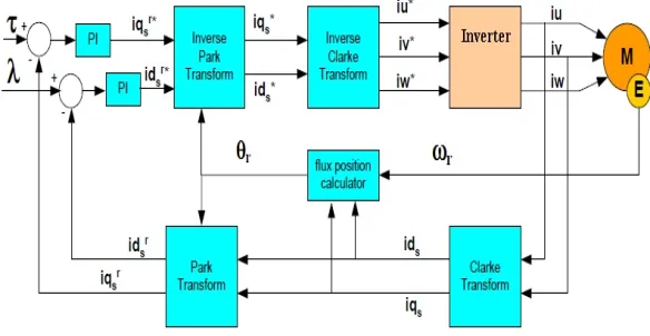
The Vector Oriented Controller (VOC) is also known as Field Oriented Controller (FOC). The main objective of this control method is to independently control the torque and the flux as in induction machines. This is done by choosing a d-q rotating references frame synchronously with the rotor flux space vector. Once the orientation is correctly achieved, the torque is controlled by the torque producing current which is the q-component of the stator current space vector. At the same time, the flux is controlled by the flux producing current, which is the d-component of the stator current space vector. Indirect field-oriented control, both the instantaneous magnitude and position of the rotor flux are supposed to be precisely known. Crucial to the success of this well known control technique is a priori knowledge of the rotor electrical term constant which varies with temperature, frequency and saturation.This method of induction machine achieves decoupled torque and flux dynamics. This is achieved by orthogonal projection of the stator current into a torque-producing component and flux-producing component. This technique is performed by two basic methods. Direct and indirect vector control. With direct field orientation, the instantaneous value of the flux is required and obtained by direct measurement using flux sensors or flux estimators, whereas indirect field orientation is based on the inverse flux model dynamics and there are three possible implementation based on the stator, rotor, or air gap flux orientation. The rotor flux indirect vector control technique is the most widely used due to its simplicity. FOC methods are attractive but suffer from one major disadvantage. They are sensitive to parameter variations such as rotor time constant and incorrect flux measurement or estimation at low speeds [3], [4]. Basic block diagram of FOC is shown in figure 1 [2].
Figure 1 Basic block diagram of VOC
III.ARTIFICIAL NEURAL NETWORK
Artificial neural networks are relatively crude electronics models based on the neural structure of human brains.ANN is an information processing paradigm that is inspired by the way biological nervous systems like the human brain the ANN can be trained to solve the lost complex non-linear problems. There are several applications of ANN in AC drives such as speed control or energy saver, adaptive speed control, current control .Neural networks can massively performs parallel operations. They are robust in nature i,e; they can still performs its overall function even if some of the neurons are not functioning. NN have two inputs, motor torque and speed and have two outputs, optimum voltage and frequency.
3.1: Neural Architecture
.
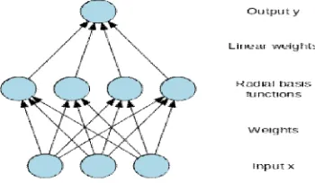
Figure 3.1: Architecture of a radial basis function network
An input vector x is used as input to all radial basis functions, each with different parameters. The output of the network is a linear combination of the outputs from radial basis functions. Radial basis function (RBF) networks typically have three layers: an input layer, a hidden layer with a non-linear RBF activation function and a linear output layer.
3.2: Algorithm
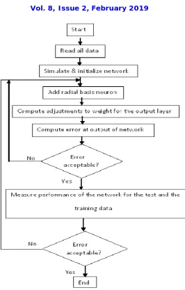
First the input is given to the input layer.
The network is simulated and initialized. For deciding the number of neurons in hidden Layer k-means algorithm is used.
Iterate until the network converges.
Calculate the error between the network’s o/p & the target o/p. if the error isn't in the desired limit go to step 3 else go to step 5.
Observe the performance of the network with the training and the test data. Re-train if necessary.
3.3: K - means Algorithm
Choose initial centres c1,...,ck.
While the clusters are changing, repeat step 3 to 4.
Assign data point pi to the cluster whose centre C is closest. This can be done by using Euclidean distance.
Update the cluster centres given by :- C= (1/n)Δ P.
Figure 4. Flowchart of RBF neural network.
IV.PI ONTROLLER
PI controller have been introduced in process control industries. The controller responds to an error signal in a close control loop and it adjust the controlled quantity to achieve the desired system response. The benefits of the PI controller is that it can be adjusted empirically by adjusting one or more gain values. The controlled parameter can be any measurable systems such as speed, torque or flux. The sign of the error indicates that the direction of change required by the control inputs. The integral (I) term of the controller can be used to eliminate small steady states errors, it also calculates the continuous running total of the error signal. Then this accumuted error signal is then multiplied by an I gain factor and it becomes the I output terms or the PI controller.
4.1: Tuning of the PI Controller- The tuning is the technique that is adopted for determining the proportional integral constants of the controller. Tuning depends upon the dynamics response of the plants.
mathematically modeled as first order system with a time constant T and delay time L as shown in block diagram [9]. The gain K corresponds to the steady state value of the output Css. The value of Kp, Ti and Td of the controllers can then be calculated as below:
Kp=1.2(T/L) --- (3) τi= 2L ---(4)
Fig 2.3 PI Controller 1st order system block diagram
V.MODULES WITH WORKING PRINCIPLES
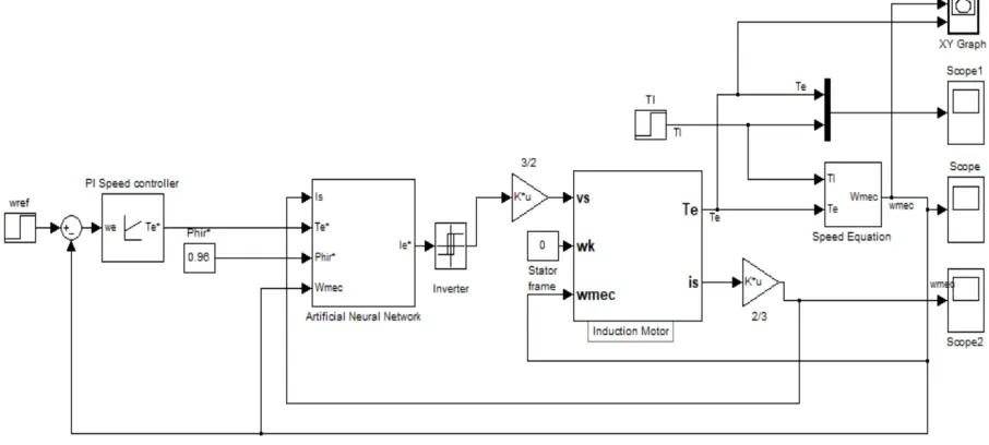
A three-phase induction motor rated at 50hp, 460V, 4pole, 50Hz is modeled in the common stator reference frame. The speed loop utilizes a PI controller to produce the quadrature-axis currents iq* which serves as the torque command. The derived direct-axis current id* serves as the rotor flux command. These currents are then transformed via the dq to abc block into the current references ia*, ib*, and ic* fed into the current regulator. The current-controlled PWM inverter is made up of three hysteresis controllers. Rotor flux field orientation is obtained in the theta calculator block.
The machine is initially operating in steady state at no load (Tl=0) at the speed wref=120rad/s. Examine the transient response due to step changes in the command speed wref and load torque Tl. Repeat the simulation for a so-called detuned case when the estimated value of the rotor time constant Tr appearing in the theta calculator differs from the actual value used for the motor parameters.
Fig 5.2: ANN Controller 1st order system
For the analysis purpose the Four condition has been taken.
Condition I – At Tl=100 & ωs = 120 rad/sec
Fig 5.3: Torque of IM at Tl = 100 N-m Fig 5.4: Speed of IM at Tl = 100 N-m
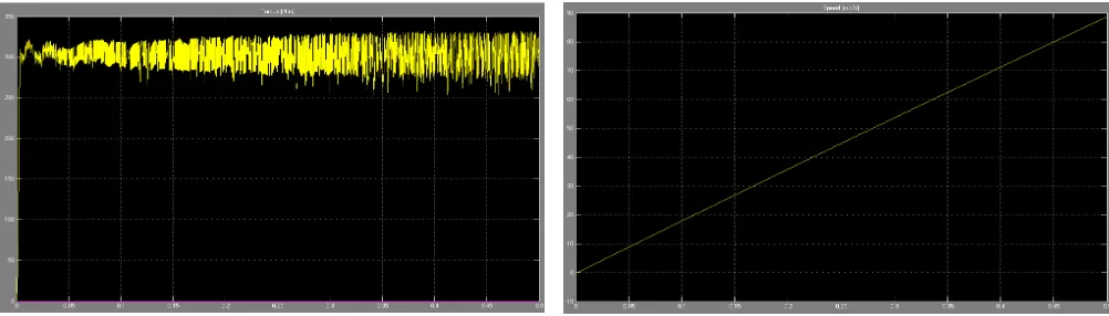
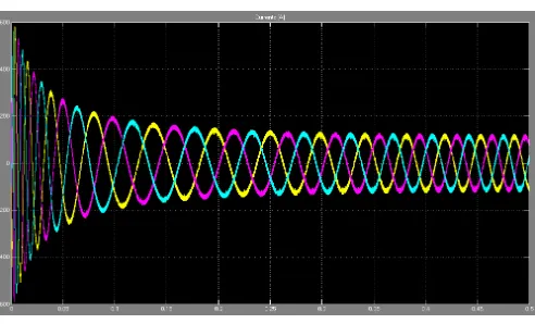
Condition II– At Tl=200 & ωs = 120 rad/sec
Fig 5.6: Torque of IM at Tl = 200 N-m Fig 5.7: Speed of IM at Tl = 200 N-m
Fig 5.8: Current waveform of IM at Tl = 200 N-m
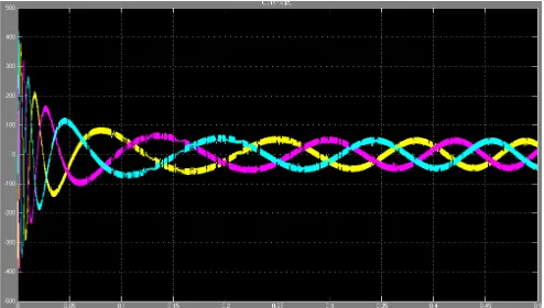
Condition III– At Tl=300 & ωs = 120 rad/sec
Fig 5.11: Current waveform of IM at Tl = 300 N-m
The performance of IM shows different varition at different Tl and speed condition in all result
VI.CONCLUSION
This project has been successfully demonstrated and PI controller and Artificial Neural Network is properly designed. We have studied and combined two controllers for speed control of indirect vector control induction motor drive. At given result and their data of induction motor current, motor torque, and speed at no load and 100,200,300 N-m load performances are examined. In future with the help of other controller, methods, Model Reference Control induction motor drives (VCIMDs) can be better controlled.
REFERENCES
[1] Shady M. Gadoue, D. Giaouris and J. W. Finch; Induction Motor Based on Genetic Algorithms and Fuzzy Logic Schemes;
[2] Uthra.R et al. “Neural network based vector control of induction motor” DOI : 10.5121/csit.2013.3409
[3] C. Mohan Krishna et al. “ Indirect vector control of induction motor using Pi Speed controller and neural networks” (IJMER) Vol.3, Issue.4, Jul - Aug. 2013 pp-1980-1987
[4] Woodley, K.M., Li, H., Foo, S.Y.: Neural Network modeling of Torque Estimation and d-q Transformation for Induction Machine. Eng. Appl. of Artif. In tell. 18(1), 57–63 (2005)
[5] . C.M.Liaw.Y.S.Kung and M.S.Ouyang Identification and control of induction machines using artificial neural networks. IEEE Trans Ind.Applicat. Vol.31.pp.612-619, 1995.
[6] H.A.Al-Rashidi, A.Gastli, A.Al-Badi, “Optimization of Variable Speed Induction Motor Efficiency Using Artificial Neural Network”. [7] M. N, et al , Neural and Fuzzy Logic Control of Drives and Power Systems, Linacre House,Jordan Hill, Oxford OX2 8DP. 2002 [8] Joachim Holtz, Sensorless Control of Induction Motor Drives, Proc. Of IEEE, Vol. 90, No. 8, Aug. 2002.
[9] KheldounAissa, and KhodjaDjalalEddine, “ Vector Control Using Series Iron Loss Model of Induction, Motors and Power Loss Minimization” World Academy of Science, Engineering
[10] A. Miloudi and A. Draou “Variable Gain PI Controller Design For Speed Control and Rotor Resistance Estimation of an Indirect Vector Controlled Induction Machine Drive ” Conference Record of the IECON ’02 Sevilla, Spain, Vol. 1, pp. 323-328, Nov 2002.
[11] Adel Merabet, MohandOuhrouche and Rung-Tien Bui,” Neural Generalized Predictive Controller for Induction Motor”. Volume 1 Number 1
pp. 83–100, University of Quebec at Chicoutimi.2006
[12] K. S. Narendra and K. Parthasarathy, "Identification and control of dynamic systems using neural networks," IEEE Trans. Neural Networks, vol.1, pp.4-27, Jan.1990.
[13] SeyedHosseinHOSSEINIandMohamad Reza BANAEI “ Neural network speed controller for induction motor based on feedback
linearization”.
[14] Jianrong Bu, LongyaXu, “A High Performance Full Fuzzy Controller for Induction Machine Drives”, IEEE APEC Conf., Vol. 2, pp. 592-596, 1998.