Available online:
https://edupediapublications.org/journals/index.php/IJR/
P a g e | 2102
Process Optimization of Electronic Component by Using
Nx-Cam Software
1
h.Pavan Kumar,
2g.Srikanth Reddy,
3dr. B Nageshwara Rao
1
M.Tech student,
2Assistant professor,
3Assistant professor. Department of Mechanical
Engineering, Avn Institute of Engineering and Technology, Hyd, T.S
ABSTRACT: The paper presents the process
plan techniques for the turn mill machine. The
turn mill machine is the CNC machine which
allows both milling and turning operations to
process in the single setup of the component.
Due to above aspects, both the machining cost
and time taken for machining is reduces.
This paper deals with turn mill operations of complex electronic component. The component has much number of operations to be performed.The component has both milling and turning operations to be performed. The component is being machined by 42 tools; it is very difficult to load 42 tools in 3 axes and 4 axes machines.Dimensions are also highly critical and complex.
This paper involves optimization of the turn mill processes or operations in order to good surface finish and to get less machining time. To optimize the turn mill process plan, CAD & CAM systems are used.
INTRODUCTION
Fuse body is a low type of resistance resistor. Fuse body that acts as a sacrificial device to provide over current protection, of either the load or source circuit. The fuse body has metal wire which is an essential component.
The metal wire melts when high current flows and interrupts the circuit to which it is
Connected. The reasons for high flow of current are short circuit, overloading or device failure.
A fuse interrupts excessive current (blows) so that further damage by overheating or fire is prevented. Wiring regulations often define a maximum fuse current rating for particular circuits. Over current protection devices are essential in electrical systems to limit threats to human life and property damage. Fuses are selected to allow passage of normal current plus a marginal percentage and to allow excessive current only for short periods. Slow blow fuses are designed to allow harmless short term higher currents but still clear on a sustained overload. Fuses are manufactured in a wide range of current and voltage ratings and are widely used to protect wiring systems and electrical equipment. Self-resetting fuses automatically restore the circuit after the overload has cleared; these are useful, for example, in aerospace or nuclear applications where fuse replacement is impossible.
Available online:
https://edupediapublications.org/journals/index.php/IJR/
P a g e | 2103
Fig shows 2D input of fuse body 3d Modeling:
Below image shows the sketch of the fuse body.
Fig shows sketch of fuse body
Below image shows revolve
Fig shows revolve of fuse body Below image shows sketch
Fig shows sketch of fuse body Below image shows extrude
Fig shows extrude option Below image shows sketch
Available online:
https://edupediapublications.org/journals/index.php/IJR/
P a g e | 2104
Fig shows extrude option Below image shows sketch
Fig shows sketch option Below image shows extrude
Fig.3.2.8. extrude option Below image shows hole option
Fig shows option of hole Below image shows option of hole
Fig shows option of hole Below image shows sketch
Available online:
https://edupediapublications.org/journals/index.php/IJR/
P a g e | 2105
Fig shows extrude option Below image shows 3D model of fuse body
Fig shows final 3D model
COMPUTER AIDED MANUFACTURING (CAM)
The main objective of the project is to obtain high surface finish and less machining time. Methodology of manufacturing fuse body
Identify suitable machine.
Selecting suitable tools for
manufacturing fuse body component. Selection of fixture.
Listing down the Sequence of operation performed on fuse body component.
Generating NC program using
NX-CAM software.
Designing tools for reducing machining time.
Identification of suitable machine:
Fuse body is manufactured on both
turning and milling machine. Facing
od_roughing
Types of CNC machine used in this project: DMG 5-axis milling machine and MORI SEIKI 4-axis CNC turning machine is used for manufacturing fuse body component.
Fig shows DMG 5-axis milling machine
Fig shows4-axis CNC MORI SIEKI turning machine
Selection of tools:
Spot drilling.
Drilling
Tapping
Face milling
Face_milling_area
Available online:
https://edupediapublications.org/journals/index.php/IJR/
P a g e | 2106
Fig shows Blank of the fuse body Below image shows part of fuse body
Fig shows part of fuse body
Turing operations on fuse body: Below image shows facing operation
Fig shows facing operations of fuse body Below image shows verification of facing operation
Fig shows verification of facing operation Below image shows ROUGH TURN_OD operation of fuse body with 1300rpm speed and 0.24mmpr feed
Available online:
https://edupediapublications.org/journals/index.php/IJR/
P a g e | 2107
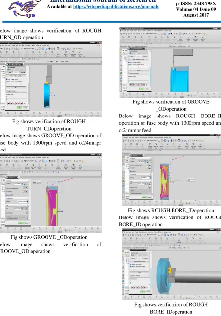
Below image shows verification of ROUGH TURN_OD operation
Fig shows verification of ROUGH TURN_ODoperation
Below image shows GROOVE_OD operation of fuse body with 1300rpm speed and o.24mmpr feed
Fig shows GROOVE _ODoperation
Below image shows verification of
GROOVE_OD operation
Fig shows verification of GROOVE _ODoperation
Below image shows ROUGH BORE_ID operation of fuse body with 1300rpm speed and o.24mmpr feed
Fig shows ROUGH BORE_IDoperation Below image shows verification of ROUGH BORE_ID operation
Available online:
https://edupediapublications.org/journals/index.php/IJR/
P a g e | 2108
Milling operations on fuse body:
Below image shows planar mill operation of fuse body with 1400rpm speed and 230mmpm feed
Fig shows planar mill operation
Below image shows verification of planar mill operation
Fig shows verification of planar mill operation Below image shows planar mill operation of fuse body with 1400rpm speed and 230mmpm feed
Fig shows planar mill operation
Below image shows verification of planar mill operation
Fig shows verification of planar mill operation Below image shows planar mill operation of fuse body with 1400rpm speed and 230mmpm feed
Available online:
https://edupediapublications.org/journals/index.php/IJR/
P a g e | 2109
Below image shows verification of planar mill operation
Fig shows verification of planar mill operation Below image shows planar mill operation of fuse body with 1400rpm speed and 230mmpm feed
Fig shows planar mill operation
Below image shows planar mill operation of fuse body with 1400rpm speed and 230mmpm feed
Fig shows planar mill operation
Below image shows verification of planar mill operation
Fig shows verification of planar mill operation
Below image shows drilling operation of fuse body with 1250rpm speed and 230mmpm feed
Fig shows drilling operation
Available online:
https://edupediapublications.org/journals/index.php/IJR/
P a g e | 2110
Fig shows verification of drilling operation Below image shows drilling operation of fuse body with 1250rpm speed and 230mmpm feed
Fig shows drilling operation
Below image shows drilling operation of fuse body with 1250rpm speed and 230mmpm feed
Fig shows drilling operation Below image shows verification of drilling operation
Fig shows verification of drilling operation Below image shows drilling operation of fuse body with 1250rpm speed and 230mmpm feed
Fig shows drilling operation
Below image shows verification of drilling operation
Available online:
https://edupediapublications.org/journals/index.php/IJR/
P a g e | 2111
Fig shows drilling operation
Below image shows verification of drilling operation
Fig shows verification of drilling operation Below image shows drilling operations of fuse body with 1250rpm speed and 230mmpm feed
Fig shows drilling operation
Below image shows verification of drilling operation
Fig shows verification of drilling operation Below image shows planar mill operation of fuse body with 1400rpm speed and 230mmpm feed
Fig shows planar mill operation
Below image shows verification of planar mill operation
Available online:
https://edupediapublications.org/journals/index.php/IJR/
P a g e | 2112
Fig shows planar mill operation
Below image shows verification of planar mill operation
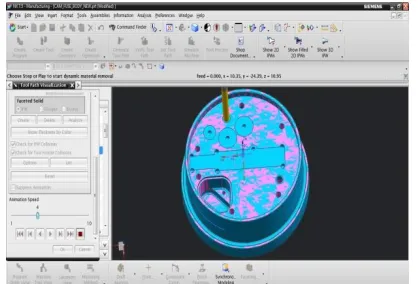
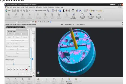
Fig shows verification of planar mill operation The manufacturing process of fuse body on CNC machine:
Raw material is placed on the machine, and degree of freedom is arrested using fixtures. 3-jaw chuck is used for arresting degree of freedom of the fuse body.
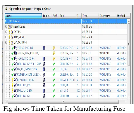
Below image shows time taken for
manufacturing fuse body.
Fig shows Time Taken for Manufacturing Fuse Body
DESIGN OF TOOLS
Tools are designed for typical operations to reduce manufacturing time and cost and to get high surface finish. These tools reduce number of operations using designed tools we can go for high cutting speed and feeds. The machining time will be reduced at high speed cutting as well as component cost is reduced.
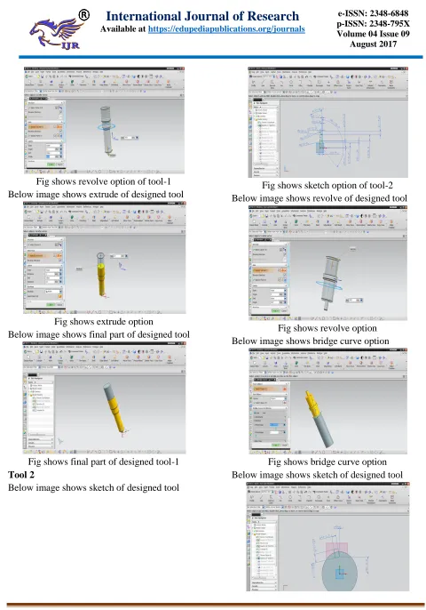
Tool 1:
Below image shows sketch of designed tool
Available online:
https://edupediapublications.org/journals/index.php/IJR/
P a g e | 2113
Fig shows revolve option of tool-1 Below image shows extrude of designed tool
Fig shows extrude option
Below image shows final part of designed tool
Fig shows final part of designed tool-1 Tool 2
Below image shows sketch of designed tool
Fig shows sketch option of tool-2 Below image shows revolve of designed tool
Fig shows revolve option Below image shows bridge curve option
Available online:
https://edupediapublications.org/journals/index.php/IJR/
P a g e | 2114
Fig shows sketch option
Below image shows extrude of designed tool
Fig shows extrude option Below image shows array of designed tool
Fig shows array of designed tool Below image shows final part of designed tool
Fig shows final part of designed tool-2 The manufacturing process of fuse body on CNC machine with designed tools.
Manufacturing process will be same for machining fuse body but designed tools were used to reduce machining time and cost of the part. The time taken for manufacturing fuse body is shown below
Fig shows Time Taken for Manufacturing Fuse Body using designed tools.
Below image shows Final component after manufacturing
RESULTS & DISCUSSION
Product cost reduction, Reduction machining time
Time and cost calculation for manufacturing fuse body as shown below
Manufacturing time taken by single component= 6hrs 24mins
Machining cost per hour for milling operations = 1200rs
Machining cost per hour for drilling operations = 800rs
Available online:
https://edupediapublications.org/journals/index.php/IJR/
P a g e | 2115
Machining cost per piece for drilling operations (machining cost per min x machining time in min) = 800/60*186min= 2480rs
Total machining cost per piece= turn-mill + drilling= 3960+2480 = 6440rs
Table1: Table of machining time& cost using default tools for manufacturing
Manufacturing component on CNC machine using Designed tools
Manufacturing time taken by single component= 5hrs 6min
Machining cost per hour for turn-mill operations = 1200rs
Machining cost per hour for drilling operations = 800rs
Machining cost per piece for turn-mill operations (machining cost per min x machining time in min) = 1200/60*198min= 3960rs
Machining cost per piece for drilling operations (machining cost per min x machining time in min) = 800/60*108min= 1440rs
Total machining cost per piece= turn-mill+drilling= 3960+1440 = 5400rs
Table of machining time& cost using designed tools for manufacturing
SET UP operati ons TIME REQUI RED IN MINS. MACHIN ING COST MACHIN ING COST/PI ECE Turn-Mill
198 RS.1200/
HR
RS.3960
Drillin 108 RS.800/H RS.1440
g R
TOTA L
306 RS.5400
Graph:
Graphical representation of manufacturing time and cost of the component
Fig shows Graph of machining time & cost
CONCLUSION
Modeling of fuse body is done using Unigraphics software.Proper tools are specified which will support for machining typical components like fuse body.Manufacturing process sequence of fuse body is shown in the document.Manufacturing time is noted when part is manufactured with regular tools, to reduce time and cost tools are designed as per the operations.New tools are designed to do 4 operations at a time and reduce manufacturing cost and timeGraphical representation of Product cost reduction, Reduction of manufacturing
times is shown in results. Graphical
representation of Product cost reduction rate of fuse body shows reduction of time as well as cost of component when manufactured by using designed tools which will reduce manufacturing time and cost of the component.Optimization of manufacturing process by using designed tools to reduce manufacturing cost and time
0 1000 2000 3000 4000 5000 6000 7000 manufacturing with regular tools manufacturing with designed tools tim e im m in s, c o st in r s TIME COST SET UP operatio ns TIME REQUIR ED IN MINS. MACHINI NG COST PER HOUR MACHINI NG COST/PIE CE Turn- Mill
198 RS.1200/H
R
RS.3960
Drilling 186 RS.800/HR RS.2480
Available online:
https://edupediapublications.org/journals/index.php/IJR/
P a g e | 2116
REFERENCES
[1] Mechanical Finish Designations
retrieved 2009-01-04.
[2] Degarmo, Black &Kohser
(2003), Materials and Processes in
Manufacturing (9th ed.), Wiley, p. 223.
[3] Whitehouse, DJ. (1994). Handbook of Surface Metrology, Bristol: Institute of Physics Publishing.
[4] G. E. Thyer (1988), Computer
Numerical Control of Machine Tools,
Heinemann
[5] Professional Publishing.
[6] Peter Smid (2003), CNC Programming
Handbook, Industrial Press Inc.
[7] Mike Lynch (1995), Managing
Computer Numerical Control Operations,
Society of
[8] Manufacturing Engineers.
[9] Tony Uccello, Derek Murphy, Frank Nanfara (2002), The CNC Workshop, Prentice Hall.
[10] Michael Mattson (2010), CNC
Programming, Delmar Cengage Learning.
[11] Sinumerik, Siemens AG (2003),
Beginner’s Manual: Milling and Turning.Tools and fixture design / Edward G. Hoffman Non-Fiction, c2004. Tools and fixture design / Edward G. Hoffman Non-Fiction, c 2004. [12] Jig, Tools & Fixture Design Thomson Learning. Otrosclientesquecompraron Jig and
Fixture Design, tambiéncompraron :