Available online: https://edupediapublications.org/journals/index.php/IJR/ P a g e | 2275
Control of grid Connected Split Source Inverter using Decoupled
Control Scheme
G. Ravi Teja
& B. Madhusudhan Reddy
1M Tech student of Dr. KVSRIT, KURNOOL, INDIA.2Assistant Professor, Department of EEE, Dr. KVSRIT, KURNOOL,INDIA.
ABSTRACT
The use of an additional boosting stage is mandatory for applications such as fuel cells-based systems, which are characterized by a low and unregulated input voltage. The increasing number of renewable energy sources and distributed generators requires new strategies for the operation and management of the electricity grid in order to maintain or even to improve the power-supply reliability and quality. In addition, liberalization of the grids leads to new management structures, in which trading of energy and power is becoming increasingly important. The power-electronic technology plays an important role in distributed generation and in integration of renewable energy sources into the electrical grid, and it is widely used and rapidly expanding as these applications become more integrated with the grid-based systems. In this thesis, the SSI is controlled by a single parameter, i.e., its dc and ac sides are controlled by the modulation index; it is of paramount importance to investigate its control scheme in grid-connected mode, which has never been studied yet. Models of the SSI dc side and proposes a modified modulation scheme combined with the commonly used synchronous reference frame control technique to achieve a decoupled control scheme of the SSI in grid-connected mode, i.e., the dc and the ac sides of the SSI can be controlled independently, which is convenient for many applications.
Keywords— Decoupled control, grid connected,
impedance-based inverters, renewable energy sources (RESs), single-stage, space vector, split-source inverter (SSI), synchronous reference frame, voltage-source inverter (VSI), Z-source inverter (ZSI).
I. INTRODUCTION
Voltage-Source inverters (VSIs) are the most common dc–ac power converters employed in any power electronic system. The VSI embraces only the buck capability with the inversion stage, i.e., the output ac voltage cannot exceed the available dc input voltage. This
point is not an issue for many applications with high dc rail. Meanwhile, several applications require the output ac voltage to exceed the input dc voltage. Hence, the use of an additional boosting stage is mandatory for these applications such as fuel cells-based systems, which are characterized by a low and unregulated input voltage.
The increasing number of renewable energy sources and distributed generators requires new strategies for the operation and management of the electricity grid in order to maintain or even to improve the power-supply reliability and quality. In addition, liberalization of the grids leads to new management structures, in which trading of energy and power is becoming increasingly important. The power-electronic technology plays an important role in distributed generation and in integration of renewable energy sources into the electrical grid, and it is widely used and rapidly expanding as these applications become more integrated with the grid-based systems.
During the last few years, power electronics has undergone a fast evolution, which is mainly due to two factors. The first one is the development of fast semiconductor switches that are capable of switching quickly and handling high powers. The second factor is the introduction of real-time computer controllers that can implement advanced and complex control algorithms. These factors together have led to the development of cost-effective and grid-friendly converters.
In the last few years renewable energies have experienced one of the largest growth areas in percentage of over 30 % per year, compared with the growth of coal and lignite energy. Grid-connected wind systems are being developed very quickly and the penetration of wind power (WP) is increasing.
Available online: https://edupediapublications.org/journals/index.php/IJR/ P a g e | 2276
power system and the grid converter, also denoted as the ‗synchronous converter‘, will be a major player in a future power system based on smart grid technologies. While the electromagnetic field has a major role in the synchronous machine, the grid converter is based mainly on semiconductor technology and signal processing but its connection filter, where the inductor is dominant, still has a crucial role to play in transient behavior.
The increase in the power that needs to be managed by the distributed generation systems leads to the use of more voltage levels, leading to more complex structures based on a single cell converter (like neutral point clamped multilevel converters) or a multi cell converter (like cascaded H-bridge or interleaved converters). In the design and control of the grid converter the challenges and opportunities are related to the need to use a lower switching frequency to manage a higher power level as well as to the availability of a more powerful computational device and of more distributed intelligence (e.g. in the sensors and in the PWM drivers).
The PV inverter is the key element of grid-connected PV power systems. The main function is to convert the DC power generated by PV panels into grid-synchronized AC power.
Historically the first grid-connected PV plants were introduced in the 1980s as thyristor based central inverters. The first series-produced transistor-based PV inverter was PV-WR in 1990 by SMA [1]. Since the mid 1990s, IGBT and MOSFET technology has been extensively used for all types of PV inverters except module-integrated ones, where MOSFET technology is dominating. Due to the high cost of solar energy, the PV inverter technology has been driven primarily by efficiency. Thus a very large diversity of PV inverter structures can be seen on the market. In comparison with the motor drive inverters, the PV inverters are more complex in both hardware and functionality. Thus, the need to boost the input voltage, the grid connection filter, grid disconnection relay and DC switch are the most important aspects responsible for increased hardware complexity. Maximum power point tracking, anti-islanding, grid synchronization and data logger are typical functions required for the PV inverters. Actually, in contrast with electrical drive industry, which is 20 years older and driven by cost where the full-bridge topology is acknowledged worldwide, new innovative topologies have recently been developed for PV inverters with the main
purpose of increasing the efficiency and reducing the manufacturing cost. As the lifetime of PV panels is typically longer than 20 years, efforts to increase the lifetime of PV inverters are also under way. Today, several manufacturers are offering extended service for 20 years.
Most of the three-phase PV inverters are not typically true three-phase three-wire inverters but rather three-phase four-wire ones. Actually they work as three independent single-phase inverters. Due to the very large variety of transformer less PV inverter topologies, the control structures are also very different. The modulation algorithm has to be specific for each topology. In the following a generic, topology invariant control structure will be presented for a typical transformer less topology with boost stage.
A. Literature Survey
Available online: https://edupediapublications.org/journals/index.php/IJR/ P a g e | 2277
intricate. Underpinned by intelligent control strategies, the power electronics technology can fulfill the requirements imposed by the distribution, transmission system operators as well as specific demands from the end-customers, especially when more advanced power devices and more accurate knowledge of the mission profiles are available.
Distributed generation (DG) has been gaining increasing attention in recent times. Among widely used DGs are wind turbines, gas turbines, fuel cells and solar cells. Generally, these sources are connected to the grid through inverters and the main function of the inverters is to deliver active power to the grid. Usually, they are operated at unity power factor but some of the systems are designed to inject or absorb reactive power. However, DG systems may not supply power to the grid continuously due to many factors like the unavailability of source and demand and price considerations. In such scenarios, the inverter used in power conversion has some unused capacity. This could be used to provide certain ancillary functions like harmonic and unbalance mitigation of the power distribution system [1]. The advantage of this approach is that a distribution-network operator who has serious power quality problems can rely on the capabilities of DG systems to provide solutions to such problems rather than implementing expensive tailor-made solutions.
Present day power consumers face numerous power quality problems. Among them are harmonics and unbalances which are of great concern. With tremendous increase of nonlinear loads connected at distribution level and with their concerted action of drawing nonlinear currents, such loads cause deterioration of voltage quality [1]–[4]. This may lead to malfunctioning of sensitive loads. The regulatory bodies have specified acceptable harmonic levels that are allowed into grids and harmonic levels that have to be maintained by the utilities.
DG systems are still not widely used for ancillary functions in power distribution systems. With the implementation of flexible DG systems, it would indeed be possible to have integrated functions like harmonic and unbalance mitigation and zero-sequence component suppression schemes embedded in DG control systems. New trends in power electronic converter systems make the implementation of such multiple functions increasingly feasible [1]–[4]. Having identified such possibilities, the main theme of this thesis is to exploit the remaining capacity of DG power converter systems, and reduce the cost of installing dedicated units for carrying out ancillary
services. Particularly, in the distribution level, it may not be economical to have dedicated systems to handle such ancillary services.
II. PROBLEM FORMULATION
The diffusion of different renewable energy sources (RESs) into the power system is continuously increasing, in which the role of power electronics technology in the employed power conditioning stage is of paramount importance to fulfill several requirements [1]– [3]. Such requirements vary from the input side, i.e., the RES, to the output side, i.e., the power grid. For the input side, the control of the RES operating point and the regulation of its output voltage are mandatory issues to be considered due to their dependence on the varying climate conditions [4],[5]. Meanwhile, for the output side, specific control schemes are implemented to comply with the standards requirements, e.g., the low harmonic contents of the injected line current [6]. During the last few years, single-stage power conversion systems has undergone a fast evolution to replace the conventional two-stage architecture, which includes a front-end dc–dc boost converter (BC) and an output voltage-source inverter (VSI) [7], [8]. This evolution has grown up to improve the overall system performance in terms of reducing its size, weight, and complexity.
Most of these single-stage topologies and their different modulation schemes have been reviewed in [1], [8], and [9]. Several research works have been done on the SSI, as in [10]–[13], where Abdelhakim et al. [10]–[12] discussed its three-level operation using the diode-clamped and flying capacitors bridges, whereas its single-phase operation is discussed in [13]. Meanwhile, its control scheme in grid-connected mode of operation has not been investigated yet. The SSI is modulated using the same eight standard states of the VSI, unlike the ZSI that utilizes an additional state, called the shoot-through state, to achieve the boosting capability. Such additional state gives an additional degree of freedom to control its dc side independently from the ac one as discussed in [14]–[16], in which the two-stage conventional control method is utilized.
Available online: https://edupediapublications.org/journals/index.php/IJR/ P a g e | 2278
commonly used with the two-stage architecture, with the so-called SSI, which is convenient for many applications. Accordingly, this thesis models the SSI dc side and proposes a modified modulation scheme combined with the synchronous reference frame control technique to achieve a decoupled control scheme of the SSI in grid-connected mode, i.e., the dc and the ac sides of the SSI can be controlled independently.
In this decoupled control scheme, the common mode term of the ac modulating signals is used to regulate the dc side, leading to an additional degree of freedom of having two control parameters like the two-stage architecture. The control system analysis and investigation of different single-stage topologies in grid-connected mode of operation is significantly increasing for different applications. In [17], the control of the three-phase multilevel quasi-Z-source inverters (qZSIs) in grid-connected mode for photovoltaic systems has been discussed, while in [18]–[20], an energy storage system based on the qZSIs without additional circuitry, taking the advantage of several passive elements without limiting the control system flexibility has been introduced. On the other hand, a controller design for the grid-connected ZSI has been discussed in [21] to improve the power quality of the distribution system. Furthermore, the use of the qZSI as an interlinking converter in a typical ac–dc hybrid microgrid has been investigated in [22], in which its control using the maximum boost approach has been studied. Hence, it was mandatory to introduce such investigation with the SSI to figure out the possibility of using it in grid-connected mode and layout the mandatory design steps to achieve this goal, and, also, highlight the associated limitations with this operation.
In this thesis, the SSI is controlled by a single parameter, i.e., its dc and ac sides are controlled by the modulation index; it is of paramount importance to investigate its control scheme in grid-connected mode, which has never been studied yet. Models of the SSI dc side and proposes a modified modulation scheme combined with the commonly used synchronous reference frame control technique to achieve a decoupled control scheme of the SSI in grid-connected mode, i.e., the dc and the ac sides of the SSI can be controlled independently, which is convenient for many applications. The introduced control scheme is analyzed and simulated using a MATLAB/Simulink and the results are presented.
III. GRID CONNECTED VOLTAGE
SOURCE CONVERTER
The main purpose of this section is to introduce the reader to different aspects of a VSC connected to a grid. Furthermore, different types of grid filters and modulation techniques will be presented. Two control principles will be introduced, the voltage angle control and the vector current control principle. Finally, the modeling of the system will be described.
Fig.3.1: The circuit of the VSC
A scheme of the main circuit of the VSC is shown in Figure 3.1. The valves are of the IGBT type. When connecting a VSC to a grid, an inductor must be mounted between the VSC, which is operating as a stiff voltage source, and the grid, which also operates as a stiff voltage source [11]. The simplest and most common grid filter is the L-filter, which has three series connected inductors, one in each phase. The LC-filter has the same series inductors, one in each phase, as the L-filter. In addition, the LC-filter has three parallel coupled capacitors. This filter type has often been supply and in most investigations, the load consists of resistors, one in each phase [12].
Available online: https://edupediapublications.org/journals/index.php/IJR/ P a g e | 2279
resonance frequency changes with grid inductance and, in addition, the harmonic distortion spectrum of the grid changes with time. The resonance problem can be reduced by using an LCL-filter [13]. The main advantages of using an LCL-filter are low grid current distortion and reactive power production. The resonance frequency can be determined almost independently of the grid configuration. The disadvantage is a more complicated system to control. The L-filter attenuation is a 20 dB/decade and the LCL-filter attenuation is a 60 dB/decade for frequencies over the resonance frequency of the filter. To improve the attenuation of the system when using the L-filter, a tuned shunt filter can be introduced which is tuned to the switching frequency of the VSC [14].
A. Three-Phase Split-Source Inverter (SSI)
Voltage-source inverters (VSIs) are the most common dc–ac power converters employed in any power electronic system. The VSI embraces only the buck capability with the inversion stage, i.e., the output ac voltage cannot exceed the available dc input voltage. This point is not an issue for many applications with high dc rail. Meanwhile, several applications require the output ac voltage to exceed the input dc voltage. Hence, the use of an additional boosting stage is mandatory for these applications such as fuel cells-based systems, which are characterized by a low and unregulated input voltage. Recently, dc–ac power converters which embrace the buck boost capability in a single stage are gaining attention due to their merits compared to the two-stage equivalent in terms of size, cost, weight, and complexity of the whole system.The most common topology in this power converter category is the conventional Z-source inverter (ZSI) topology, exploits an impedance network that comprises four passive elements in addition to a diode that carries the full power to work as a buck-boost stage. Several topologies exist for the so-called ZSI in addition to the conventional one; among them the quasi ZSI (qZSI) and the current fed qZSI are introduced. Other topologies like the switched-inductor ZSI and the switched-inductor qZSI are discussed. Moreover, the semi ZSI is another ZSI topology introduced as a low cost solution for single-phase photo-voltaic systems.
The conventional topology having the disadvantage includes Complexity and the Output ac voltage cannot exceed the available dc input voltage. ZSI
requires an additional switching state out of the conventional eight states, besides having a discontinuous input current and utilizing four passive elements. Hence, this thesis proposes a different topology called the split-source inverter (SSI). This topology utilizes a reduced passive element count compared with the ZSI, in addition to a diode for each inverter leg. The advantages of the proposed topology, compared with the ZSI, are: a continuous input current, a standard modulation strategy that employs the same eight states of the VSI, and a constant inverter voltage with a low frequency component. This topology is derived by integrating a boost converter into a three-phase VSI, by connecting the boost inductor to the switching nodes of the inverter legs via diodes. The employment of the boost converter in dc–ac power conversion was first studied, where studies the possibility of making a combination from two boost converters to get a sinusoidal output voltage. The possibility of eliminating the boost converter semiconductor active switch is by utilizing the lower semiconductor active switch of a single-phase VSI for power factor correction application.
Fig.3.2: Split source Inverter
The merits of split source inverter include the continuous input current, Power factor correction and Constant inverter voltage with a low frequency component.
The applications of the above inverter are with high dc rail and fuel cell based systems.
IV. SIMULATION RESULTS
Available online: https://edupediapublications.org/journals/index.php/IJR/ P a g e | 2280
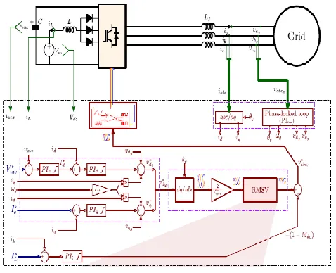
shown in Fig. 4.1. Simulation studies are carried out in the MATLAB/SIMULINK environment.
Fig.4.1: Proposed topology Table 4.1: Simulation parameters
S. No. Parameter Value
1. Filter iductance 4.3mH
2. Inverter Voltage 425V
3. Filter resistance 1.3 ohm
4. Grid frequency 50Hz
5. Capacitance 120 micro farad
6. Inductance 1.7 mH
The control scheme has been designed and the different PI controllers are designed considering a bandwidth of 500 Hz for the output current and input current control loops (i.e., for PId , PIq , and PIi ), and 50 Hz for the dc-link voltage control loop (i.e., for PIv ). It is worth noting that the bandwidth of the dc-link voltage control loop is much higher than the practical value, which has been chosen to figure out the limit of the proposed control scheme. The parameters of the different PI controllers are as follows: The proportional and integral gains equal 13.3 and 8080, respectively, for the output current controllers, 0.0648 and 5.93, respectively, for the dclink voltage controller, and 0.0129 and 3.98, respectively, for the input current controller.
Using the designed parameters in Table 5.1, a MATLAB/Simulink model has been implemented to test the proposed control scheme. The steady-state simulation results of this model are shown in Fig. 5.2 during the normal system conditions (i.e., rated input current and
nominal grid voltage), where the grid line-to-line voltages
vgabc, the inverter output currents iabc , the dc-link voltage
vinv, and the input current iL are shown for one fundamental
cycle.
This MATLAB/Simulink model is used again to test the proposed control scheme considering different transients. The considered transients are as follows: a step variation in the input current reference as shown in Fig.5.3, a grid voltage swell of 15% for five fundamental cycles are shown in Fig.5.4, and a grid voltage sag of 15% for five fundamental cycles as well is shown in Fig.5.5. Finally, Fig. 5.6 shows the same simulation results introduced in Fig. 5.2 but considering a grid voltage swell of 23%, which is higher than the designed maximum limit. According to these shown simulation results, the regulation index and the modulation index are independently controlled. Hence, a complete decoupled control of the two parameters is achieved and the possibility of controlling the SSI using the two-stage control scheme has been proved under the proposed control scheme.
0 0.02 0.04 0.06 0.08 0.1 0.12 0.14 0.16 0.18 0.2 -300
-200 -100 0 100 200 300
Time (sec)
V
g
ab
c
(V
)
Available online: https://edupediapublications.org/journals/index.php/IJR/ P a g e | 2281
0 0.02 0.04 0.06 0.08 0.1 0.12 0.14 0.16 0.18 0.2 -8
-4 0 4 8
Time (sec)
iab
c(A
)
(b) The inverter output currents
0 0.02 0.04 0.06 0.08 0.1 0.12 0.14 0.16 0.18 0.2 385
405 425 445 465 485
Time (sec)
V
in
v
(V
)
(c) The dc link voltage, Vinv
0.1 0.11 0.12 0.13 0.14 0.15 0.16 0.17 0.18 0.19 0.2
0 5 10 15 20
Time (sec)
iL
(A
)
(d) Input current, iL
Fig.4.2:Grid-connected SSI simulation results at steady-state
0 0.02 0.04 0.06 0.08 0.1 0.12 0.14 0.16 0.18 0.2 -300
-200 -100 0 100 200 300
Time (sec)
V
ab
cg
(V
)
(a) Grid Voltage
0 0.02 0.04 0.06 0.08 0.1 0.12 0.14 0.16 0.18 0.2
-8 -4 0 4 8
Time (sec)
iab
c
(A
)
(b) The inverter output currents
0.050 0.1 0.15 0.16
100 200 300 400 425 500 600
Time (sec)
V
in
v
(V
)
(c) The dc link voltage, Vinv
0 0.05 0.1 0.15 0.2
0 5 10 15 20
Time (sec)
iL
(A
Available online: https://edupediapublications.org/journals/index.php/IJR/ P a g e | 2282 (d) Input current, iL
Fig.4.3: A step variation in the input current
0 0.02 0.04 0.06 0.08 0.1 0.12 0.14 0.16 0.18 0.2
-300 -150 0 150 300
Time (sec)
V
ab
cg
(V
)
(a) Grid Voltage
0 0.05 0.1 0.15 0.2
-8 -4 0 4 8
Time (sec)
i
ab
c
(A
)
(b) The inverter output currents
0 0.02 0.04 0.06 0.08 0.1 0.12 0.14 0.16 0.18 0.2
385 405 425 445 465 485
Time (sec)
V
in
v
(V
)
(c) The dc link voltage, Vinv
0.05 0.1 0.15 0.2
-5 0 5 10 15 20
Time (sec)
iL
(A
)
(d) Input current, iL
Fig.4.4: Grid voltages swell of 15%
0 0.05 0.1 0.15 0.2
-300 -200 -100 0 100 200 300
Time (sec)
V
ab
cg
(V
)
(a) Grid Voltage
0 0.05 0.1 0.15 0.2
-8 -4 0 4 8
Time (sec)
iab
c
(A
)
Available online: https://edupediapublications.org/journals/index.php/IJR/ P a g e | 2283
0 0.05 0.1 0.15 0.2
385 405 425 445 465 485
Time (sec)
V
in
v
(V
)
(c) The dc link voltage, Vinv
0.05 0.1 0.15 0.2
-5 0 5 10 15 20
Time (sec)
iL
(A
)
(d) Input current, iL
Fig.4.5: Grid voltages sag of 15%
0.05 0.1 0.15
-300 -200 -100 0 100 200 300
Time (sec)
V
ab
cg
(V
)
(a) Grid Voltage
0 0.01 0.02 0.03 0.04 0.05 0.06
-10 -5 0 5 10
Time (sec)
iab
c(A
)
(b) The inverter output currents
0.060 0.1 0.15
100 200 300 400 500
Time (sec)
V
in
v
(V
)
(c) The dc link voltage, Vinv
0.060 0.1 0.15
5 10 15 20
Time (sec)
iL
(A
)
(d) Input current, iL
Fig.4.6: A grid voltage of 23% to show the saturation effect
V.
CONCLUSION
Available online: https://edupediapublications.org/journals/index.php/IJR/ P a g e | 2284
many applications. This control scheme is based on a combination of the proposed RMSV modulation scheme and the commonly used synchronous reference frame control technique. The SSI dc side was modeled first and then the introduced control scheme was discussed. This proposed work tested the introduced control scheme using MATLAB/Simulink model, considering different transients, and then verified the simulation. As discussed in the simulation results, the system is properly controlled and a fully decoupled control of both the input dc current and the output ac current was achieved.
VI. REFERENCES
[1]. A. Abdelhakim, P. Mattavelli, and G. Spiazzi, ―Three-phase split-source inverter (SSI): Analysis and modulation,‖ IEEE Trans. Power Electron., vol. 31, no. 11, pp. 7451–7461, Nov. 2016.
[2]. J.M. Carrasco et al., ―Power-electronic systems for the grid integration of renewable energy sources: A survey,‖ IEEE Trans. Ind. Electron., vol. 53, no. 4, pp. 1002–1016, Jun. 2006.
[3]. F. Blaabjerg, Y. Yang, and K. Ma, ―Power electronics—Key technology for renewable energy systems—Status and future,‖ in Proc. 3rd Int. Conf. Elect. Power Energy Convers. Syst., Oct. 2013, pp. 1–6.
[4]. V. Samavatian andA. Radan, ―Ahigh efficiency input/output magnetically coupled interleaved buck-boost converter with low internal oscillation for fuel-cell applications: CCM steady-state analysis,‖ IEEE Trans. Ind. Electron., vol. 62, no. 9, pp. 5560–5568, Sep. 2015. [5]. J. Kan, S. Xie, Y. Wu, Y. Tang, Z. Yao, and R. Chen, ―Single-stage and boost-voltage grid-connected inverter for fuel-cell generation system,‖ IEEE Trans. Ind. Electron., vol. 62, no. 9, pp. 5480–5490, Sep. 2015. [6]. Z. Yao, L. Xiao, and J. M. Guerrero, ―Improved control strategy for the three-phase grid-connected inverter,‖ IET Renew. Power Gener., vol. 9, no. 6, pp. 587–592, 2015.
[7]. O. Ellabban and H. Abu-Rub, ―Z-source inverter: Topology improvements review,‖ IEEE Ind. Electron. Mag., vol. 10, no. 1, pp. 6–24, Spring 2016.
[8]. Y. Siwakoti, F. Z. Peng, F. Blaabjerg, P. C. Loh,
and G. Town, ―Impedance source networks for electric
power conversion part I: A topological review,‖ IEEE
Trans. Power Electron., vol. 30, no. 2, pp. 699–716, Feb.
2015.
[9]. Y. P. Siwakoti, F. Z. Peng, F. Blaabjerg, P. C.
Loh, G. E. Town, and S. Yang, ―Impedance-source networks for electric power conversion part II: Review of
control and modulation techniques,‖ IEEE Trans. Power
Electron., vol. 30, no. 4, pp. 1887–1906, Apr. 2015.
[10]. A. Abdelhakim and P. Mattavelli, ―Analysis of
the three-level diode clamped split-source inverter,‖ in
Proc. 42nd Annu. Conf. IEEE Ind. Electron. Soc., Oct.
2016, pp. 3259–3264.
[11]. A. Abdelhakim, P. Mattavelli, and G. Spiazzi,
―Three-level operation of the split-source inverter using
the flying capacitors topology,‖ in Proc. 8th IEEE Int.
Power Electron. Motion Control Conf.,May 2016, pp.
223–228.
[12]. A. Abdelhakim, P. Mattavelli, and G. Spiazzi,
―Three-phase three-level flying capacitors split-source
inverters: Analysis and modulation,‖ IEEE Trans. Ind.
Electron, to be published, doi: 10.1109/TIE.2016.2645501.
[13]. S. S. Lee andY. E. Heng, ―Improved single phase
split-source inverter with hybrid quasi-sinusoidal and
constant PWM,‖ IEEE Trans. Ind. Electron., vol. 64, no. 3,
pp. 2024–2031, Mar. 2017.
[14]. K. M. Tsang and W. L. Chan, ―Decoupling
controller design for z-source inverter,‖ IET Power
Electron., vol. 8, no. 4, pp. 536–545, 2015.
[15]. Y. Li, S. Jiang, J. G. Cintron-Rivera, and F. Z.
Peng, ―Modeling and control of quasi-z-source inverter for
distributed generation applications,‖ IEEE Trans. Ind.
Electron., vol. 60, no. 4, pp. 1532–1541, Apr. 2013.
[16]. A. A. Hakeem, A. Elserougi, A. E. Zawawi, S.
Ahmed, and A.M. Massoud, ―A modified modulation scheme for capacitor voltage control of renewable
energy-fed grid-connected Z-source inverters,‖ in Proc. 38th
Annu. Conf. IEEE Ind. Electron. Soc., Oct. 2012, pp. 886–
893.
[17]. Y. Liu, B. Ge, H. Abu-Rub, and F. Z. Peng, ―An
effective control method for three-phase quasi-z-source cascaded multilevel inverter based grid-tie photovoltaic
power system,‖ IEEE Trans. Ind. Electron., vol. 61, no.
12, pp. 6794–6802, Dec. 2014.
[18]. B. Ge et al., ―An energy-stored quasi-z-source
inverter for application to photovoltaic power system,‖
IEEE Trans. Ind. Electron., vol. 60, no. 10, pp. 4468–
4481, Oct. 2013.
[19]. D. Sun, B. Ge, W. Liang, H. Abu-Rub, and F. Z.
Available online: https://edupediapublications.org/journals/index.php/IJR/ P a g e | 2285
IEEE Trans. Ind. Electron., vol. 62, no. 9, pp. 5458–5467,
Sep. 2015.
[20]. Y. Liu, B. Ge, H. Abu-Rub, and F. Z. Peng,
―Control system design of battery-assisted quasi-Z-source
inverter for grid-tie photovoltaic power generation,‖ IEEE
Trans. Sustain. Energy, vol. 4, no. 4, pp. 994–1001,Oct.
2013.
[21]. C. J. Gajanayake, D. M. Vilathgamuwa, P. C.
Loh, R. Teodorescu, and F. Blaabjerg, ―Z-source-inverter-based flexible distributed generation system solution for
grid power quality improvement,‖ IEEE Trans. Energy
Convers., vol. 24, no. 3, pp. 695–704, Sep. 2009.
[22]. J. Khajesalehi, K. Sheshyekani, M. Hamzeh, and
E. Afjei, ―Maximum constant boost approach for controlling quasi-z-source-based interlinking converters in
hybrid AC-DC microgrids,‖ IET Gener., Transm. Distrib.,
vol. 10, no. 4, pp. 938–948, 2016.
[23]. Y. Jia, J. Zhao, and X. Fu, ―Direct grid current control of LCL-filtered grid-connected inverter mitigating
grid voltage disturbance,‖ IEEE Trans.Power Electron.,
vol. 29, no. 3, pp. 1532–1541, Mar. 2014.
[24]. M. Huang, X. Wang, P. C. Loh, and F. Blaabjerg,
―LLCL-filtered grid converter with improved stability and
robustness,‖ IEEE Trans. Power Electron., vol. 31, no. 5,
pp. 3958–3967, May 2016.
[25]. R. Teodorescu, M. Liserre, and P. Rodriguez,
Grid Converters for Photovoltaic and Wind Power
Systems. New York, NY, USA: Wiley, 2011.
[26]. D. Dong, B. Wen, D. Boroyevich, P. Mattavelli,
and Y. Xue, ―Analysis of phase-locked loop low-frequency stability in three-phase grid-connected power converters
considering impedance interactions,‖ IEEE Trans. Ind.
Electron., vol. 62, no. 1, pp. 310–321, Jan. 2015.
[27]. V. Blasko and V.Kaura, ―A new mathematical
model and control of a three phase AC-DC voltage source
converter,‖ IEEE Trans. Power Electron., vol. 12, no. 1,
pp. 116–123, Jan. 1997.
[28]. Y. Zhang and C. Qu, ―Model predictive direct
power control of PWM rectifiers under unbalanced
network conditions,‖ IEEE Trans. Ind. Electron., vol. 62,
no. 7, pp. 4011–4022, Jul. 2015.
[29]. B. Subudhi and R. Pradhan, ―A comparative study on maximum power point tracking techniques for
photovoltaic power systems,‖ IEEE Trans.Sustain. Energy,