Magnetic and Electric Coupling Analysis for Angular Misalignment
of Spiral Resonators in WPT Systems
Yangjun Zhang* and Tatsuya Yoshikawa
Abstract—Angular misalignment is an issue for many potential applications of wireless power transfer (WPT). It is necessary to keep coupling coefficient, especially the magnetic coupling to be insensitive to angular misalignment. This paper analyzes the coupling between the spiral resonators when one resonator rotates with respect to the other. The quantitative data of magnetic and electric coupling components as well as the total coupling coefficient in angular misalignments are presented. Furthermore, a 3D spiral resonator which is less sensitive to angular misalignment is proposed. The coupling when the 3D spiral rotates is studied and the results of analysis and experiment both show that the proposed 3D spiral resonator can keep coupling coefficient at a certain level under angular misalignment.
1. INTRODUCTION
Electromagnetic induction, coupling and radiation are three main methods for wireless power transfer (WPT) [1–3]. Electromagnetic coupling method has received a lot of attention due to its high efficiency, low cost and the capability to transfer power in a longer distance than the induction method [2–4]. In a WPT system of electromagnetic coupling, coupling coefficient between the resonators is a key parameter because the power is transferred via electric and magnetic couplings between transmitting and receiving resonators. Other important parameters of a WPT system include Q value of resonator, impedance matching and others [5–7].
Electromagnetic coupling WPT systems can be designed based on magnetic resonance coupling, electric resonance coupling or mixed magnetic and electric resonance coupling. Magnetic coupling is currently more popular than electric coupling in the field of wireless power transfer, especially in the mid-range WPT applications [4, 8–10]. No matter which coupling is utilized, it is necessary to maintain the strength of coupling between the transmitting and receiving elements at a certain level.
Some research works have been reported on the study of electromagnetic coupling between RF devices [11–15]. Quantitative data on the electric and magnetic coupling components reveal the nature of coupling between the transmitting and receiving elements. Such data will greatly help engineers to design a good WPT system. An example based on magnetic and electrical components is the WPT system reported in [10], where a distance-insensitive WPT system is proposed by making use of the out-of-phase characteristic of the electric and magnetic coupling coefficients. Our previous studies also presented some results on the electromagnetic coupling [16, 17]. Some of them focused on the coupling in WPT systems [18–20].
In a WPT system, coupling between the resonators depends on many factors such as structure of resonator, distance and alignment between the resonators and environmental conditions. Among these factors, angular misalignment is an issue for many potential WPT systems. Alignment angle between the resonators is difficult to fix during wireless power transferring. For example, in a home wireless
Received 5 September 2018, Accepted 5 November 2018, Scheduled 16 November 2018
* Corresponding author: Yangjun Zhang ([email protected]).
power delivery, a receiving element in a mobile device will change its orientation to the transmitting element. For a biomedical device implanted in a human body, the device may rotate with respect to the power transmitting element. Some methods and optimization techniques are reported to maintain the performance of the WPT system even in an angular misalignment [21–23]. However, there are few studies of quantitative analysis reported on the electromagnetic coupling under angular misalignment.
This study analyzes the coupling between the coupled spiral resonators, focusing on the influence of angular misalignment on the electric and magnetic coupling components. The paper is organized as follows. Section 2 introduces the method to decompose the coupling into electric and magnetic coupling components. Section 3 analyzes the coupling between the conventional planar spiral resonators when one spiral rotates with respect to the other. Section 4 proposes a 3D spiral resonator which is less sensitive to angular misalignment. Conclusion is drawn in Section 5.
2. ANALYSIS METHODS
The conventional method to calculate the coupling coefficient is the frequency method [12]. If the resonant frequencies of two resonators are set equal originallyk is calculated by the following equation
k= 2(fH −fL)
(fH +fL) (1)
where fH and fL are the higher and lower split frequencies of the coupled resonators, respectively. As the equation indicates, only the total coupling coefficient can be obtained by the frequency method.
The overlap integral method can calculate the total coupling coefficient, but also gives the electric and magnetic coupling components [13, 16, 17]. The overlap integral method is based on the coupled mode theory and calculates the total coupling coefficient as follows,
k=
V
(μH∗1·H2−εE∗1·E2)dV
√
W1W2
, (2)
where E1, E2 are the electric fields of two resonators before coupling, respectively; H1, H2 are the
magnetic fields of two resonators before coupling, respectively; and W1, W2 are the energy of two
resonators before coupling, respectively. The magnetic and electric coupling componentskm andkeare calculated as in Equations (3) and (4), respectively.
km =
V
μH∗1·H2dV
√
W1W2
(3)
ke =
V
εE∗1·E2dV
√
W1W2
(4)
In our study,E andH fields are obtained by a commercial simulation software HFSS@;k,km andkeare calculated by a program made by ourselves according to Equations (2), (3) and (4). Our previous studies have proved that the overlap integral method is useful in the coupling analysis between electromagnetic devices [16–20].
3. COUPLING ANALYSIS FOR ROTATION OF PLANAR SPIRAL RESONATOR
3.1. Coupling in Mirror Symmetric and Anti-Symmetric Alignments
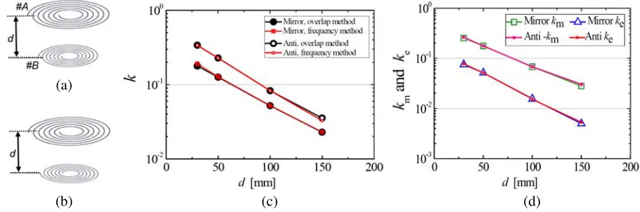
At first, the basic arrangements of the coupled planar spirals are analyzed. The basic arrangements are mirror symmetric and anti-symmetric as shown in Figure 1(a) and Figure 1(b), where one of planar spirals rotates 180◦ with respect to the other. Here as an example to show the validity of the overlap method, we comparekobtained by the frequency method and the overlap integral method in Figure 1(c). The results agree very well.
Figure 1(d) shows the calculated k, km and ke for two basic arrangements as functions of the distance between the spirals. Note thatkmis positive in mirror symmetric alignment, and it is negative in anti-symmetric alignment. The results indicate that ke in the mirror-symmetric and anti-symmetric alignments are almost the same at the same distance. This is also true for|km|. Because ofk=|km−ke|, mirror-symmetric alignment results in a weak coupling, and anti-symmetric alignment produces a strong coupling.
(b) (a)
(c) (d)
Figure 1. Calculated results of coupling coefficients for the coupled planar spiral resonators. Structure of planar spiral #A: Wire diameter dw = 1 mm, out diameter D= 240 mm, turn number T = 18 and pitchp= 6 mm. Structure of planar spiral #B: Wire diameter dw= 1 mm, out diameter D= 120 mm, turn number T = 34 and pitch p = 1.56 mm. (a) Planar spirals in mirror symmetric alignment. (b) Planar spirals in anti-symmetric alignment. (c) Comparison of k calculated by the two methods (d)km and ke as functions of the distance between the spirals.
3.2. Coupling at Arbitrary Alignment Angle
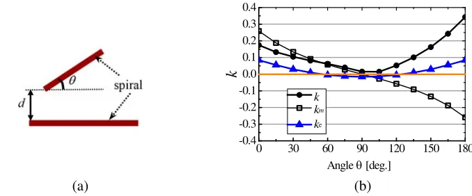
In this subsection, we further investigate the coupling when the alignment angle between the planar spirals is an arbitrary value. Figure 2(a) shows the analysis model, and (b) shows the calculated k,km and ke when the alignment angle θvaries from 0◦ to 180◦. The minimum distance between the spirals is kept at 30 mm when one spiral rotates.
The calculated results show following features of the coupling when one planar spiral rotates.
1) km is significantly larger thanke.
2) Total coupling coefficient k changes asθ changes. It becomes very weak when θ is around 90◦. k is not 0 atθ= 90◦ because of the contribution from the electric coupling.
3) km changes significantly whenθ changes. It becomes 0 whenθis 90◦.
(b) (a)
30 60 90 120 150 180 0
-0.4 -0.3 -0.2 -0.1 0.0 0.1 0.2 0.3 0.4
k
Angle [deg.]θ k
km
ke
Figure 2. Coupling coefficients when the alignment angle θ between the planar spirals varies from 0◦ to 180◦. (a)Alignment angleθ between the planar spirals. d= 30 mm. (b)k,km and ke as functions of θ.
4. A 3D SPIRAL RESONATOR FOR WPT SYSTEM
The proposed 3D resonator is constructed with 3 spirals as shown in Figure 3(a). Three spirals are arranged in a way that the 3D resonator has a balanced magnetic field. Three lumped capacitors are used to adjust resonant frequency. Figure 3(b) shows the simulated magnetic field for the proposed 3D resonator. It can be seen that the magnetic components perpendicular to the spirals are all in the directions of out of the resonator at this phase. Such a balanced magnetic field is helpful for avoiding km variation in the resonator rotation.
C1
C2 C3
(b) (a)
Figure 3. (a) The proposed 3D spiral resonator. C1=C2 =C3= 8 pF. Three spirals have an identical
structure. Structure of spiral: Wire diameter dw = 1 mm, out diameter D = 120 mm, turn number T = 15 and pitch p= 3 mm. (b) Simulated magnetic field for the 3D spiral resonator.
4.1. Coupling Analysis for the 3D Spiral Resonator Rotation
The coupling is analyzed when the 3D spiral resonator rotates. The analysis model is shown in Figures 4(a) and (b). The transmitting planar spiral #Ais the same as that in Section 3. The minimum distance between the resonators is kept at the same 30 mm, for a comparison with the result of Figure 2. Mirror symmetric and anti-symmetric alignments are distinguished according to the alignment state of Spiral #A and Spiral #C1 atθ= 0◦, referring Figure 4(a).
It can be noted that rotation around z axis has little effect on the coupling. Rotation around x axis is discussed in this paper. Figure 4(c) shows the calculated results of k,km and ke as functions of alignment angleθfor mirror symmetric alignment. The results show thatkm is not 0 at any alignment angle. km varies in the range of 0.014 to 0.073. Because of the symmetric structure of the 3D resonator, coupling coefficients at otherθ angles are similar to those ofθ from 0◦ to 60◦.
d
θ
x y z
Spiral #A Spiral #C1
(b)
(a) (c)
15 30 45 60 75 90
0 0.00 0.02 0.04 0.06 0.08 0.10
k
Angle θ [deg.] k km ke
Figure 4. Coupling analysis for the 3D spiral resonator rotation. (a) Simulation model and rotation direction. (b) Alignment angle θ. (c) Coupling coefficients as functions of θ in mirror symmetric alignment.
15 30 45 60 75 90
0 0.00 0.02 0.04 0.06 0.08 0.10
k
Angle [deg.] θ k -km ke
Figure 5. Coupling coefficient as functions of θ in anti-symmetric alignment.
15 30 45 60 75 90
0 10-6 10-5 10-4 10-3 10-2 10-1 100
|k
m|
Angle [deg.]θ
Planar spiral - planar spiral 3D spiral - planar spiral, mirror symmetric
3D spiral - planar spiral, anti-symmetric
Figure 6. Comparison of magnetic coupling coefficientkm.
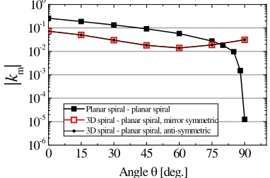
Figure 6 compareskmfor the rotation of the 3D spiral and a planar spiral. Compared to the planar spiral rotation, km for the 3D spiral resonator is not sensitive to the alignment angle θ.
4.2. Experiment
This subsection presents the experimental results when the 3D spiral resonator rotates. A prototype of 3D spiral resonator is made in our laboratory, as shown in Figure 7. The resonant frequencies of the 3D spiral and a conventional planar spiral are set at equal originally. Figure 8 shows the measured resonant frequencies for the 3D spiral resonator and planar spiral. It indicates that the two resonators have the same resonant frequency of 15.20 MHz.
The total coupling coefficient is only verified here because there are no methods to measure magnetic or electric coupling components so far. The experimental setup to measure the split frequencies of the coupled spiral resonators is shown in Figure 9. Figure 10 shows the measured and simulated k as functions of alignment angle θ when the 3D resonator rotates. The results include the coupling coefficients when the 3D and planar spirals are in mirror symmetric and anti-symmetric alignments. It is shown that the measured results are generally consistent with the simulated ones.
4.3. Improvement Example of the 3D Resonator
Figure 7. A prototype of the 3D spiral resonator.
0 30 60 90 120 150 180 210 240 270 15.1
15.2 15.3 15.4 15.5
Resonant frequency [MHz]
Distance between the loop and the resonator [mm]
Planar spiral 3D spiral
Figure 8. The measured resonant frequencies of the 3D spiral resonator and a conventional planar spiral resonator.
d Network Analyzer
Loop coil
Loop coil
Figure 9. The experimental setup to measure the resonant frequencies for the coupled spiral resonators.
0 10 20 30 40 50 60 70 80 90
0.00 0.02 0.04 0.06 0.08 0.10 0.12 0.14
k
Rotating angle [degree], d=30mm
Mirror, simulation Mirror, measured Anti, simulationt Anti, measured
Figure 10. The measured and simulated results of total coupling coefficient as functions of alignment angleθ.
15 30 45 60 75 90
0 0.00 0.02 0.04 0.06 0.08
k
Angle θ [deg.]
km, with core μr=1000 km, without core ke, with core μr=1000 ke, without core
0 15 30 45 60 75 90
0.00 0.02 0.04 0.06 0.08 0.10 0.12
k
m& k
e
Angle [deg.]
(b) (a)
as cube and sphere to be omnidirectional when it rotates. On the other hand, the dimension of the resonators should be decided based on its actual application. Furthermore, the coupling can be made stronger by inserting a magnetic core into the 3D resonator. Figure 11 shows the calculated k,km and ke for a 3D resonator when a magnetic core of μr = 1000 is inserted into the resonator. Compared to the 3D resonator without a magnetic core, it can be seen that kand km are much improved.
5. CONCLUSION
This study analyzes magnetic and electric coupling components for the coupled spiral resonators when one resonator rotates with respect to the other. The total coupling coefficientk, the magnetic coupling componentkm and the electric coupling componentke are calculated using the overlap integral method. The quantitative data of coupling on angular misalignment are presented.
The study first analyzes the coupling between two conventional planar spirals. The results show that the total coupling k becomes very small when the alignment angle of two planar spirals is near 90◦. When alignment angle θ is 90◦,km= 0. The analysis also indicates that km andke counteract in a mirror symmetric alignment resulting in a weak total coupling, andkm andkeadd each other making a strong coupling in an anti-symmetric alignment.
The study then proposes a 3D spiral resonator which is less sensitive to the angular misalignment. The proposed resonator is constructed with 3 open spirals and has a balanced magnetic distribution. The experimental results on the prototype of the 3D spiral resonator are consistent with the analysis ones, and both results prove that the proposed spiral is less sensitive to the angular misalignment.
REFERENCES
1. Tesla, N., “Transmission of electrical energy without wire,”Elect. World Eng., Mar. 5, 1904, Online Available: ww.tfcbooks.com/tesla/.
2. Kurs, A., A. Karalis, R. Moffatt, J. D. Joannopoulos, P. Fisher, and M. Soljacic, “Wireless power transfer via strongly coupled magnetic resonances,” Science, Vol. 317, 83–86, Jul. 2007.
3. Shonohara, N., Wireless Power Transfer via Radiowaves, ISTE Ltd. and John Wiley & Sons, Inc., 2014.
4. Awai, I., “Magnetic resonant wireless power transfer,” Nikkei Electronics, 2011 (in Japanese). 5. Ohira, T., “Maximum available efficiency formulation based on a black-box model of linear two
port power transfer systems,”IEICE Electronics Express, ELEX, Vol. 11, No. 13, 1–6, #20140448, Jun. 2014.
6. Zhang, J., X. Yuan, C. Wang, and Y. He, “Comparative analysis of two-coil and three-coil structures for wireless power transfer,” IEEE Transactions on Power Electronics, Vol. 32, No. 1, 341–352, 2017.
7. Tierney, B. B. and A. Grbic, “Design of self-matched planar loop resonators for wireless nonradiative power transfer,”IEEE Transactions on Microwave Theory and Techniques, Vol. 62, No. 4, 909–919, 2014.
8. Hui, S. Y. R., W. Zhong, and C. K. Lee, “A critical review of recent progress in mid-range wireless power transfer,”IEEE Transactions on Power Electronics, Vol. 29, No. 9, 4500–4511, 2014. 9. Fernandes, R. D., J. N. Matos, and N. B. Carvalho, “Resonant electrical coupling: Circuit model
and first experimental results,”IEEE Transactions on Microwave Theory and Techniques, Vol. 63, No. 9, 2983–2990, 2015.
10. Zhang, X. Y., C. D. Xue, and J. K. Lin, “Distance-insensitive wireless power transfer using mixed electric and magnetic coupling for frequency splitting suppression,”IEEE Transactions on Microwave Theory and Techniques, Vol. 65, No. 11, 4307–4316, 2017.
11. Hong, J.-S., “Couplings of asynchronously tuned coupled microwave resonators,”IEE Proceedings-Microwaves, Antennas and Propagation, Vol. 147, No. 5, 354–358, 2000.
13. Awai, I., “New expressions for coupling coefficient between resonators,” IEICE Trans. Electron., E88C, No. 12, 2295–2301, Dec. 2005.
14. Awai, I., S. Iwamujra, H. Kubo, and A. Sanada, “Separation of coupling coefficient between resonators into electric and magnetic contributions,” IEICE, Vol. J88-C, No. 12, 1033–1039, 2005 (in Japanese).
15. Elnaggar, S. Y., R. J. Tervo, and S. M. Mattar, “Coupled mode theory applied to resonators in the presence of conductors,” IEEE Transactions on Microwave Theory and Techniques, Vol. 63, No. 7, 2124–2132, 2015.
16. Awai, I. and Y. Zhang, “Coupling coefficient of resonators,” IEICE Trans. Electron, Vol. J89-C, No. 12, 962–968, 2006 (in Japanese).
17. Awai, I. and Y. Zhang, “Phenomenological and essentialismic theories of coupling between the resonators,”IEICE Trans. Electron, Vol. J98-C, No. 12, 314–321, 2015 (in Japanese).
18. Awai, I., Y. Zhang, T. Komori, and T. Ishizaki, “Coupling coefficient of spiral resonators used for wireless power transfer,”2010 Asia-Pacific Microwave Conference, 773–776, Yokohama, Japan, Dec. 2010.
19. Zhang, Y., T. Yoshikawa, and I. Awai, “Analysis of electric and magnetic coupling components for spiral resonators used in wireless power transfer,” 2014 Asia-Pacific Microwave Conference, 1366–1368, 2014.
20. Zhang, Y., T. Yoshikawa, and T. Kitahara, “A quantitative analysis of coupling for a WPT system including dielectric/magnetic materials,” Progress In Electromagnetics Research Letters, Vol. 72, 127–134, 2018.
21. Sampath, J. P. K., A. Arokiaswami, and D. M. Vilathgamuwa, “Figure of merit for the optimization of wireless power transfer system against misalignment tolerance,” IEEE Transactions on Power Electronics, Vol. 32, No. 6, 4359–4369, 2017.
22. Lin, D., C. Zhang, and S. Y. Ron Hui, “Mathematic analysis of omnidirectional wireless power transfer — Part-II three-dimensional systems,” IEEE Transactions on Power Electronics, Vol. 32, No. 1, 613–624, 2017.