PATIL, VIKRAM CHANDRAKANT. Efficiency Improvement Techniques in Liquid Piston Compressor for Ocean Compressed Air Energy Storage Application. (Under the direction of Dr. Paul I. Ro).
Modern electricity infrastructure needs an efficient large-scale energy storage system to accommodate energy supply from intermittent renewable energy resources. Ocean compressed air energy storage system (OCAES) is a promising large-scale energy storage system. In OCAES, energy is stored in the form of compressed air under the Ocean. This research is aimed at achieving technological advancement of OCAES to attain an efficient large-scale energy storage system. Energy and exergy analysis of various OCAES configurations is performed first to identify OCAES configuration with high efficiency. Isothermal OCAES shows significantly higher efficiency over adiabatic and diabatic OCAES with potential to reach a 72% roundtrip efficiency of energy storage. However, attainment of such a high efficiency is conditional on achieving near-isothermal compression and expansion of air. Compression of air using liquid piston is researched to attain efficient near-isothermal compression. Understanding the heat transfer mechanisms during compression is crucial in the design and development of efficient liquid piston compressor. Therefore, a thorough investigation of heat transfer in liquid piston compressor is performed experimentally. It is observed that convective thermal resistance between air and chamber has significant contribution in total thermal resistance; therefore, heat transfer enhancement techniques to enhance the heat transfer coefficient between gas and chamber can lead to significant improvements in the isothermal efficiency of the liquid piston compressor.
injection pressure shows higher improvement in compression efficiency and an optimal spray angle which can create smaller droplets with minimum loss of droplets due to the impact on chamber wall can lead to a marginal improvement in efficiency. Water spray injection is a highly effective technique to achieve near-isothermal compression with an isothermal efficiency up to 95% at a high power density. Moreover, aqueous foam based heat transfer enhancement is investigated in liquid piston compressor. Experiments are performed with the use of aqueous foam generated under different foam generation conditions. The volume of aqueous foam in the chamber, the air flow rate of foam generation, and various foam generator designs are considered in this investigation. A higher volume of aqueous foam in the compression chamber leads to a further increment in isothermal efficiency, however, with higher cyclic variability. Also, experiments highlight the potential of reduction in cyclic variability through the foam generator design. Overall, the use of aqueous foam in the liquid-piston compressor is effective in achieving an isothermal efficiency up to 92%. Additionally, another heat transfer enhancement using metal wire mesh spirals of aluminum and copper materials are investigated in liquid piston compression. Metal wire meshes have a high thermal conductivity and a large heat surface area and therefore are hypothesized to improve heat transfer from the gas to the liquid inside the liquid piston compressor. Both aluminum and copper meshes are observed to improve isothermal efficiency of compression to 88-90% from the base efficiency of 82-84%.
Energy Storage Application
by
Vikram Chandrakant Patil
A dissertation submitted to the Graduate Faculty of North Carolina State University
in partial fulfillment of the requirements for the degree of
Doctor of Philosophy
Mechanical Engineering
Raleigh, North Carolina. 2019
APPROVED BY:
_______________________________ _______________________________ Dr. Paul I. Ro Dr. Alexei Saveliev
Committee Chair
ii DEDICATION
iii BIOGRAPHY
Vikram Patil was born in Sangli located in the state of Maharashtra in India. He graduated with Master’s in Mechanical Engineering from Indian Institute of Science, Bangalore, India in June 2013 and with Bachelor of Technology in Mechanical Engineering from Walchand College of Engineering, Sangli, India in May 2011. He worked as an Assistant Manager in the Research and Development division of Bajaj Auto Limited in Pune, India from July 2013 to July 2015.
iv TABLE OF CONTENTS
LIST OF TABLES ... vii
LIST OF FIGURES ... viii
CHAPTER 1: Introduction ... 1
1.1. Compressed Air Energy Storage ... 3
1.2. Ocean Compressed Air Energy Storage (OCAES) ... 5
1.3. Research Objectives ... 6
CHAPTER 2: Energy and Exergy Analysis of OCAES Concepts ... 7
2.1. Introduction ... 8
2.2. OCAES Configurations ... 12
2.2.1. Diabatic OCAES ... 13
2.2.2. Adiabatic OCAES ... 14
2.2.3. Isothermal OCAES ... 16
2.2.4. Liquid Piston based OCAES ... 17
2.3. Energy and Exergy Analysis ... 18
2.3.1. Electric Motor and Generator ... 19
2.3.2. Hydraulic Pump/Motor ... 20
2.3.3. Compressor ... 20
2.3.4. Cooler ... 21
2.3.5. Air Pipelines Connecting Various Components ... 21
2.3.6. Thermal Energy Storage (TES) ... 22
2.3.7. Air Storage ... 22
2.3.8. Heater ... 23
2.3.9. Expander ... 23
2. 4. Numerical Simulations... 24
2.5. Results and Discussion ... 27
2.5.1. Diabatic OCAES ... 27
2.5.2. Adiabatic OCAES ... 28
2.5.3. Isothermal OCAES ... 30
2.5.4. Liquid Piston based OCAES ... 31
v
CHAPTER 3: Heat Transfer in Liquid Piston Compressor ... 35
3.1. Introduction ... 37
3.2. Analytical Model ... 40
3.3. Experiments ... 45
3.4. Results and Discussion ... 47
3.4.1. Pressure and Temperature Plots ... 47
3.4.2. Experiments with different Stroke Time of Compression ... 50
3.4.3. Rate of Heat Transfer and Compression Work ... 52
3.4.4. Heat Transfer Coefficient ... 55
3.4.5. Thermal Resistances ... 59
3.4.6. Overall Heat Transfer Coefficient ... 61
3.4.7. Isothermal Efficiency of Compression ... 62
3.5. Conclusions ... 64
CHAPTER 4: Spray Injection in Liquid Piston Compressor ... 65
4.1. Introduction ... 67
4.2. Experimental Setup ... 71
4.2.1. Liquid Piston Setup ... 71
4.2.2. Spray Injection Setup ... 72
4.2.3. Measurement Devices ... 75
4.2.4. Range of Experiments ... 76
4.3. Results and Discussion ... 77
4.3.1. Pressure and Temperature Plots ... 77
4.3.2. Effect of Injection Pressure ... 79
4.3.3. Effect of Spray Nozzle Angle ... 89
4.3.4. Effect of Stroke Time of Compression ... 93
4.4. Conclusions ... 97
CHAPTER 5: Aqueous Foam in Liquid Piston Compressor ... 100
5.1. Introduction ... 101
5.2. Conceptual Framework ... 105
5.2.1. Bubble Dynamics in Aqueous Foams ... 106
vi
5.2.3. Isothermal Compression ... 111
5.3. Experimental Procedure ... 113
5.3.1. Liquid Piston Compressor Setup ... 113
5.3.2. Aqueous Foam Generation Setup ... 114
5.3.3. Experimental Cases ... 117
5.4. Results and Discussion ... 118
5.4.1. Bubble Dynamics during Compression ... 118
5.4.2. Effect of Aqueous Foam Volume ... 120
5.4.3. Variability with the Use of Aqueous Foam ... 121
5.4.4. Effect of Air Flow Rate of Aqueous Foam Generation ... 123
5.4.5. Effect of Foam Generator Designs ... 126
5.5. Conclusions ... 131
CHAPTER 6: Metal Wire Mesh Spiral in Liquid Piston Compressor ... 133
6.1. Introduction ... 134
6.2. Conceptual Framework ... 136
6.3. Experimental Setup ... 139
6.4. Results and Discussion ... 141
6.4.1. Effect of Metal Wire Mesh Material ... 141
6.4.2. Effect of Compression Stroke Time ... 144
6.4.3. Isothermal Compression Efficiency ... 147
6.5. Conclusions ... 149
CHAPTER 7: Efficiency Improvement in Liquid-piston based OCAES ... 150
7.1. Introduction ... 151
7.2. Efficiency Improvement Techniques ... 153
7.2.1. Spray Injection ... 153
7.2.2. Aqueous Foam ... 154
7.2.3. Metal Wire Mesh ... 155
7.3. OCAES Efficiency ... 156
7.4. Conclusions ... 159
vii LIST OF TABLES
Table 2.1: Stochastic Assignments in Monte Carlo Simulation ... 25 Table 2.2: Thermodynamic properties and mass flow rates of air at different state points for Diabatic OCAES system (See Figure 1 for state points) ... 26 Table 2.3: Thermodynamic properties and mass flow rates of air at different state points for Adiabatic OCAES system (See Figure 2 for state points) ... 26 Table 2.4: Thermodynamic properties and mass flow rates of air at different state points for Isothermal OCAES system (See Figure 3 for state points)... 26 Table 3.1: Model Parameters of the non-linear regression model for convective heat transfer coefficient during compression with polycarbonate chamber. ... 58 Table 4.1: Measurement devices and corresponding accuracies. ... 75 Table 4.2: Compression Work and Spray Work for compression at different injection
pressures. ... 86 Table 5.1: Analysis of Variance (ANOVA) table for efficiencies with foam generator
designs... 129 Table 6.1: Polytropic Index and Isothermal Efficiency of Compression with and without
viii LIST OF FIGURES
Figure 1.1: Energy storage and power output of various energy storage options [10]. ... 2
Figure 1.2: Conceptual schematic of compressed air energy storage. ... 3
Figure 1.3: Conceptual schematic of Ocean Compressed Air Energy Storage (OCAES) [18]. .... 5
Figure 2.1: Schematic of diabatic OCAES ... 13
Figure 2.2: Schematic of adiabatic OCAES ... 15
Figure 2.3: Schematic of isothermal OCAES ... 16
Figure 2.4: Schematic of a liquid piston based Isothermal OCAES system. ... 17
Figure 2.5: Exergy flow in diabatic OCAES ... 28
Figure 2.6: Exergy flow in adiabatic OCAES ... 29
Figure 2.7: Exergy flow in isothermal OCAES ... 30
Figure 2.8: Overall exergy efficiency of different types of OCAES. ... 31
Figure 2.9: Experimental setup of liquid piston compressor. ... 32
Figure 2.10: Roundtrip efficiency of liquid piston based OCAES for different polytropic indices. ... 33
Figure 3.1: Control Volume in Liquid piston compressor ( --- represents control volume) ... 41
Figure 3.2: Thermal Circuit for liquid piston compressor ... 42
Figure 3.3: Pressure-Volume plot indicating isothermal and polytropic compression ... 44
Figure 3.4: Experimental Setup of Liquid piston compressor ... 46
Figure 3.5: Various Compression chambers used in the study. ... 47
Figure 3.6: Pressure over time for 10 continuous compression cycles ... 49
Figure 3.7: Temperature over time for 10 continuous compression cycles ... 49
ix Figure 3.9: Pressure over compression time for various stroke times of compression (With
Polycarbonate chamber)... 51
Figure 3.10: Temperature of air over compression time for various stroke times of compression (With Polycarbonate chamber) ... 51
Figure 3.11: Temperature of the inner surface of compression chamber over compression time for various stroke times of compression (With Polycarbonate chamber). ... 52
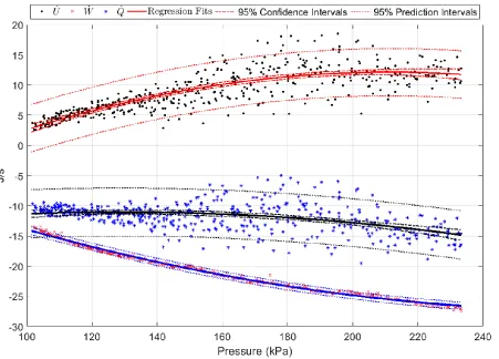
Figure 3.12: Rate of change of internal energy(U), compression work (W) and rate of heat transfer(Q) during compression (With polycarbonate chamber and 5.1 s compression stroke). ... 54
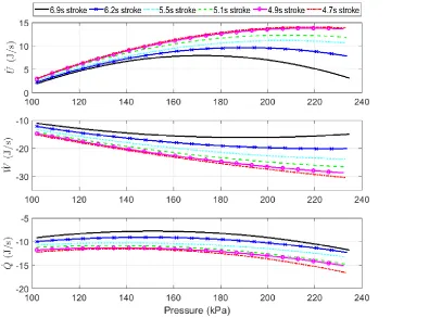
Figure 3.13: Comparison of U, W and Q for different stroke times of compression ... 55
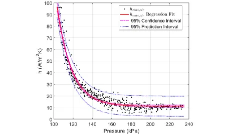
Figure 3.14: Convective heat transfer coefficient between air and cylinder wall during compression (With polycarbonate chamber and 5.1 s compression stroke). ... 56
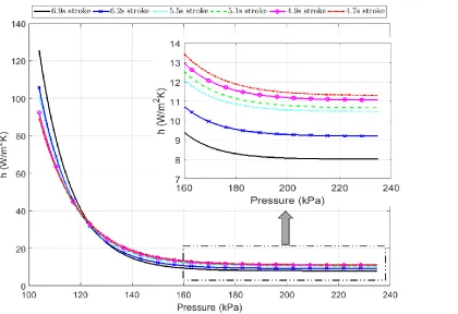
Figure 3.15: Comparison of convective heat transfer coefficient between air and cylinder wall for different stroke times of compression (With polycarbonate chamber) ... 59
Figure 3.16: Contribution of thermal resistances during compression process for different compression chambers. ... 60
Figure 3.17: Overall heat transfer coefficient for compression with different compression chambers. ... 62
Figure 3.18: Isothermal Efficiency for compression with different compression chambers. ... 63
Figure 4.1: A table-top setup of Liquid piston compressor. ... 72
Figure 4.2: Spray Injection Setup ... 73
Figure 4.3: Spray pattern with full cone whirl nozzle. ... 74
Figure 4.4: Pressure and Temperature vs time for ten continuous compression cycles without spray. ... 77
Figure 4.5: Pressure and Temperature vs time for ten continuous compression cycles with sprays of different injection pressures. ... 78
Figure 4.6: Flow rates of the spray with different injection pressure during a single compression cycle. ... 80
x Figure 4.8: Temperature plots for a single compression cycle without and with spray of
different injection pressures. ... 82
Figure 4.9: Pressure volume plots for a compression cycle with spray of different injection pressures in comparison with adiabatic and isothermal plots. ... 83
Figure 4.10: Zoomed view of pressure-volume plots of Figure 4.9 near the end of compression. ... 84
Figure 4.11: Isothermal efficiency of compression with spray of different injection pressures. .. 88
Figure 4.12: Temperature plots with different spray angles during a single compression cycle. . 90
Figure 4.13: Pressure-volume plots with spray injection of different spray angles during compression. (With 30 psi injection pressure and medium level of stroke time) ... 91
Figure 4.14: Isothermal efficiency with spray injection from different nozzle angles for various injection pressures. ... 92
Figure 4.15: Temperature plots with and without spray injection for a compression cycle with different stroke times. (With 30 psi injection pressure and 90° spray angle) . 94 Figure 4.16: Pressure-volume plots with and without spray injection for a compression cycle with different stroke times. (With 30 psi injection pressure and 90° spray angle) .. 95
Figure 4.17: Zoomed view of pressure-volume plots of Figure 4.16 near the end of compression. ... 96
Figure 4.18: Isothermal efficiency with and without spray injection at various stroke time of compression for various injection pressures. ... 97
Figure 5.1: Foam generation by injecting air through fritted disk [149]. ... 105
Figure 5.2: Basic structures of single cell [127]. ... 107
Figure 5.3: Experimental Setup of Liquid piston compressor ... 114
Figure 5.4: Foam Generator designs of 2.5 mm hole diameters with and without tubes. ... 115
Figure 5.5: Compression chamber with Aqueous Foam. ... 116
Figure 5.6: Aqueous foam bubble dynamics during compression process. ... 119
Figure 5.7: Temperature-pressure plot with foam of different volume in the chamber. ... 120
xi Figure 5.9: Temperature-pressure for multiple cycles using about half of the chamber with
foam. ... 122
Figure 5.10: Temperature-pressure for multiple cycles using full chamber with foam. ... 123
Figure 5.11: Aqueous foam generated using different flow rates of air source. ... 124
Figure 5.12: Temperature-pressure plots with aqueous foam generated using different air source flow rate. ... 124
Figure 5.13: Isothermal efficiency of compression with the aqueous foam generated by various flow rates of air source. ... 125
Figure 5.14: Temperature-pressure plots using foam generator of 2.5 mm holes. ... 127
Figure 5.15: Temperature-pressure plots using foam generator of 5 mm holes. ... 128
Figure 5.16: Isothermal efficiency with foam generated from different foam generator designs... 130
Figure 6.1: Conceptual schematic of liquid piston compressor with Metal Wire Mesh. ... 137
Figure 6.2: Experimental Setup of Liquid Piston Compressor. ... 140
Figure 6.3: Aluminum and Copper metal wire mesh sprials. ... 141
Figure 6.4: Pressure during compression process with and without mesh in the chamber. ... 142
Figure 6.5: Temperature during compression process with and without mesh in the chamber. 142 Figure 6.6: Temperature-Pressure (Normalized) plots with and without mesh in the chamber. 144 Figure 6.7: Pressure during compression of different stroke times with and without mesh. ... 145
Figure 6.8: Temperature during compression of different stroke times with and without mesh. ... 146
Figure 6.9: Temperature-pressure (normalized) plots during compression of different stroke times with and without mesh in the chamber... 147
1
CHAPTER 1: Introduction
The electricity sector is one of the major contributors to global warming emissions worldwide. In the United States, about 29% of global warming emissions come from the electricity sector and most of those emissions originated from fossil fuels like coal and natural gas [1, 2]. Most of the renewable energy sources produce little or no global warming emissions and life cycle emissions (i.e. emissions from each stage of life- manufacturing, installation, operation, and decommissioning) are minimal for renewable energy resources [3]. Electricity generation from renewable energy sources is desired to reduce energy dependency from fossil fuels and curtain global warming emissions. A comprehensive study by the U.S. Department of Energy’s National Renewable Energy Laboratory (NREL) shows that the United States can generate most of its electricity from renewable energy by 2050 [4].
2 Various energy storage technologies are currently engaged in the power applications which include pumped hydro storage, compressed air energy storage, thermal storage, battery storage, flywheel, capacitor-based energy storage, and superconducting magnetic energy storage (SMES) [9]. Each of these technologies varies in their energy storage and power output capacity for production of a viable energy storage system. A comparison of these technologies with consideration of energy storage capacity, power output, and storage duration is shown in Figure 1.1. Additionally, these technologies differ in various characteristics like their cost, lifetime, cycle efficiency, and environmental impact [10]. Utility-scale energy storage systems are needed for the integration of renewable energy resources in the electric grid [11]. The pumped hydro storage and large compressed air energy storage are key technologies for the large scale energy storage. Pump hydro storage is efficient compared to the compressed air storage systems but pumped hydro is restricted by the availability of suitable geological locations [12].
3
1.1. Compressed Air Energy Storage
Compressed air energy storage (CAES) system is a reliable large-scale energy storage technology with relatively low specific investment cost [13]. In a CAES system, energy is stored in the form of mechanical energy, or more precisely exergy, of pressured air. A schematic of the CAES system is shown in Figure 1-2. A typical CAES system consists of the following major components.
a) Electric Motor b) Air Compressor
c) Compressed Air Storage Reservoir d) Air Turbine/ Expander
e) Generator
4 During the storage mode, off peak electricity is used to compress the atmospheric air to high pressure, and compressed air is stored in the high-pressure reservoir. An electric motor consuming electricity drives the compressor to compress air to the high pressure. When electricity demand is high, the stored high pressurized air is expanded through the turbine to generate electricity in the recovery mode. CAES systems can store energy for a significantly long time-frame in terms of weeks or months while having a large-scale energy storage capacity.
Two large-scale CAES plants are in operation, one is in Huntorf, Germany [14] and the other is in McIntosh, Alabama-USA [15]. The CAES plant Huntorf, Germany was the first commercial set up in the 1970s, initially with a 290 MW capacity which was later expanded to 321 MW in 2006. The second commercial CAES plant was built in McIntosh, Alabama in 1991 for a 110 MW capacity. The cycle efficiency of the McIntosh plant is 54% which considerably higher than cycle efficiency of Huntorf plant (42%). This is due to the application of recuperator in McIntosh plant which is completely omitted in the Huntorf plant [16]. For the air storage system, both the plants use underground salt caverns which provide a large storage volume for the high energy storage capacity.
5
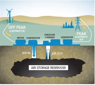
1.2. Ocean Compressed Air Energy Storage (OCAES)
Ocean compressed air energy storage (OCAES) is a promising utility-scale energy storage system [17]. In OCAES, compressed air is stored under the ocean water. A schematic of the OCAES system is shown in Figure 1.3. In OCAES, energy is stored in the form of compressed air in an underwater storage device. This storage device can be a receiver vessel, vented to sea water, mounted on the seafloor and connected to the compressed air source via pipeline [18]. Alternatively, flexible fabric energy bag architecture can be used for underwater air storage [19]. OCAES uses hydrostatic pressure in the deep ocean in order to store compressed air at a constant high pressure. Due to the constant air pressure in OCAES, significant improvement in the useful isothermal energy of compressed air has been shown over the land-based compressed air energy storage [20]. For energy recovery, compressed air is passed through an expander to generate electricity. Development of an efficient compressor and expander for OCAES application would lead to a highly efficient large-scale energy storage system.
6
1.3. Research Objectives
The primary objective of this research is to facilitate technological advancements of Ocean Compressed Air Energy Storage (OCAES). Development of an efficient OCAES configuration is crucial in this regard. Therefore, energy and exergy analysis of various OCAES concepts is performed first to identify an efficient system configuration and potential of efficiency improvements with the use of advanced technology. As compressor is one of the key components of the OCAES system, development of an efficient compressor is naturally beneficial for efficiency improvement of OCAES system.
Development of an efficient compressor is contingent on the realization of a near-isothermal compression process. Liquid piston compressor can be effectively used to attain a near-isothermal compressor. Understanding of heat transfer characteristics during compression is crucial for the realization of the near-isothermal compressor using liquid piston. Therefore, a thorough investigation of heat transfer in the liquid piston compressor is performed experimentally. Furthermore, various heat transfer enhancement techniques are explored in liquid piston compressor for efficiency improvement. Specifically, heat transfer enhancement techniques using water spray injection, aqueous foam, and metal wire mesh are studied experimentally in a liquid piston compressor. Isothermal efficiency of the compression process with the use of these techniques is evaluated to identify the potential of these methods in achieving an efficient near-isothermal compression.
7
CHAPTER 2: Energy and Exergy Analysis of OCAES Concepts
8
2.1. Introduction
Electricity generation from renewable energy sources plays important role in reducing dependence on fossil fuels and in curtailing greenhouse gas emissions. However, renewable energy sources such as wind, solar, tidal, wave etc. are sporadic in nature. The variability of power from the renewable energy sources makes it hard to integrate with the electric grid [21]. Utility-scale energy storage systems are needed to improve the utilization of renewable energy resources in electric grid [11]. Compressed air energy storage (CAES) system is a reliable large-scale energy storage method with relatively low specific investment cost [13]. In CAES system, intermittent energy is used to compress the atmospheric air to the high pressure and compressed air is stored in the high-pressure reservoir. When electricity demand is high, the stored high pressurized air is expanded through the turbine to generate electricity. Two large-scale CAES plants are in operation, one is in Huntorf, Germany [14] and the other is in McIntosh, Alabama-USA [15]. In both the plants, compressed air is stored in an underground cavern. However, these underground caverns are constant volume air storage reservoirs. In constant volume air storage systems, charging and discharging processes results in pressure variation. These varying conditions can result in low efficiencies of compression and expansion due to deviation from the designed points [22]. This can be avoided by utilizing ocean depth for storage of the compressed air in which high-pressure environment under the water can be effectively used for creating constant pressure storage system [23]. Such an ocean compressed air storage (OCAES) system can effectively integrate multiple energy sources located offshore with high system efficiency.
9 next section with more details. Roundtrip efficiency (also called end-to-end efficiency) is an important parameter to assess the efficacy of an energy storage system. As processes in the OCAES system are accompanied by heat and work transfer, it is very difficult to understand the efficiency of an OCAES system using first law of thermodynamics. This is because the first law of thermodynamics deals with heat and work equally. Therefore, roundtrip efficiency based on exergy analysis which is based on the second law of thermodynamics would be beneficial in better understanding the characteristics of the different types of OCAES systems.
Various studies have investigated different types of CAES configurations based on energy and exergy analysis. Kim et al. reviewed the main drawbacks of the existing CAES systems and presented energy and exergy analysis of various innovative CAES concepts [24]. They investigated concepts like adiabatic CAES, isothermal CAES, micro-CAES combined with air-cycle heating and cooling, and constant-pressure CAES combined with pumped hydro storage. Their analysis illustrated that drawbacks of existing CAES systems can be addressed by employing innovative CAES concepts. Bagdanavicius et al. investigated the potential for using heat generated during compression stage of CAES with a district energy system [25]. Exergy and exergoeconomic analysis of CAES and CAES with thermal storage were performed by them. Their analysis showed that utilization of waste heat increases energy efficiency from 48% for the CAES to almost 86% for CAES with thermal storage. They also observed that highest exergy destruction occurs in the heat exchangers during compression stage.
10 suggested that developing high-temperature thermal storage (>600 oC) and temperature resistant
materials for compressors are key elements in achieving higher efficiency. Grazzini et al. presented a thermodynamic analysis of multistage adiabatic CAES [27]. They proposed a comprehensive set of criteria for the design of adiabatic CAES based on a detailed thermodynamic analysis of the design parameters and influence on system efficiency, with attention to heat transfer devices. An exergy analysis was presented by Tessier et al. on adiabatic CAES system utilizing a cascade of phase change materials for waste heat storage and recovery [28]. Incorporation of phase change materials predicted to show a 15% increased efficiencies of storage and recovery over the current design. An experimental study of CAES system with thermal energy storage by Wang et al. has shown a mere 22.6% roundtrip efficiency [29]. A recent detailed review on CAES has been presented in [30].
The existing CAES plants in Huntorf and McIntosh are of a diabatic type and show roundtrip efficiency of 42% and 54% respectively. The Huntorf plant was primarily designed to provide reserve power and blackstart capability where high efficiency is of minor importance. The McIntosh plant was designed to perform load shifting on a weekly basis, which requires the cycle efficiency to be as high as possible. The McIntosh plant could achieve considerably higher efficiency over Huntorf plant using a recuperator to reduce exergy loss. The concept of adiabatic CAES using Thermal Energy Storage (TES) was also considered during development of these plants, however, diabatic CAES is preferred at that time due to technical and economic advantages [30].
11 at the high outlet temperature essential for adiabatic operation. Recent developments in TES have shown good prospects in achieving adiabatic CAES in practice [31]. An adiabatic CAES is under development under the project name ‘ADELE-ING’ which could show roundtrip efficiency up to 70% [32]. Another approach in achieving high efficiency is through isothermal CAES. Technically, it was very difficult to achieve isothermal operation at high power density. However, recent developments in liquid piston compressor [33] and heat transfer enhancement techniques in the liquid piston [34-36] could result in near-isothermal compression and expansion at high power density. Thermodynamic and economic review of CAES by Rogers et al. [37] indicates that efficiencies of advanced adiabatic CAES and isothermal CAES have been increased by over 30% and energy storage densities have been improved by a factor of 5 using near-surface piping.
A multi-level underwater CAES system integrated with battery pack is proposed by Wang et al [38]. Their thermodynamic analysis shows that round-trip exergy efficiency of the multi-level underwater CAES varies from 62% to 81% in different working mode. Advanced exergy analysis of an underwater CAES by Wang et al. indicates exergy efficiency of 53.6% under real conditions with theoretical maximum exergy efficiency of 84.3% [39]. Clearly, there is a great potential for performance improvement of underwater CAES. A study by Cheung et al. indicates that pipe diameter, turbine, air compressor and air storage depth have the greatest influence on system performance of underwater CAES [40]. Multi-objective optimization of an underwater CAES with objectives of maximizing roundtrip efficiency and operating profit, and minimizing cost rate is performed by Cheung et al. using genetic algorithm [41]. Their analysis indicated roundtrip efficiency of 68.5% and operating profit of $53.5 per cycle for the preferred system designs.
12 systems would help in understanding these better. Preliminary studies of exergy analysis for various OCAES configurations and end-to-end efficiency of liquid piston based OCAES have been presented earlier in [42, 43]. In this chapter, detailed analysis of various OCAES concepts using energy and exergy analysis is presented. This would help in assessing improvement areas in achieving higher roundtrip efficiency with OCAES.
Investment costs associated with different types of OCAES would also vary as the technology used in these configurations differs considerably. The compressor and expander in the diabatic OCAES are mature technologies whereas the same in the adiabatic and isothermal OCAES are still in the development stages. Also, the cost of Thermal Energy Storage (TES) used in adiabatic OCAES differs significantly based on the kind of TES system used. Broadly, there are three types of TES systems- sensible heat TES, latent heat TES and thermo-chemical TES. In general, latent heat TES and thermo-chemical TES are more expensive than sensible heat TES, however, former could be economically viable with a high number of operating cycles [31]. Although the cost of different OCAES configurations might differ significantly, this study only focuses on efficiency aspect without accounting any cost difference. However, an economic assessment of these OCAES configurations would be necessary before investment decisions. This study could provide a framework for an economic assessment of different OCAES by monetizing efficiencies incorporating cost difference.
2.2. OCAES Configurations
13 Diabatic OCAES, Adiabatic OCAES, and Isothermal OCAES. These system configurations are discussed in this section.
2.2.1. Diabatic OCAES
In the diabatic OCAES system, in energy storage mode, air is compressed using conventional compressors and cooled to the surrounding temperature before sending it to the storage system. Compression process increases the temperature of air due to the heat of compression which is dissipated before sending air to the storage device. This results in loss of thermal energy of compression due to cooling. In energy recovery mode, the air from the storage is heated using fuel and then passed through the expander to generate electricity.
The schematic of Diabatic OCAES is shown in Figure 2.1. Process 1-2 represents compression of atmospheric air using air compressor run using electric motor operating on excess electric energy. The motor efficiency and losses in the compressor would result in loss of energy/exergy during this process. Compressed air from the compressor is then passed through the cooler (process 2-3) before sending it to the underwater air storage system. A significant amount of heat energy
14 (thermal exergy) is lost in the cooler. Process 3-4 indicates charging and discharging from the air storage system. Mechanical exergy (energy in pressure form) in the high-pressure air is stored in the underground storage. There can be a small amount of loss of energy/exergy due to leakage and pressure drop in the storage system. In process 4-5, high-pressure air is heated using external heat input (thermal exergy) to increase expansion work. The process 5-6 is the expansion process in which mechanical exergy in the form of electrical energy is delivered. However, process 5-6 involves loss of energy/exergy due to inefficiencies in expansion process and also loss of energy/exergy from the exhaust gas.
2.2.2. Adiabatic OCAES
15 It can be seen that cooler and heater in the diabatic OCAES are replaced with thermal energy storage (TES) in the adiabatic OCAES configuration. The diabatic OCAES uses fuel in the heater, therefore, it cannot be considered as a pure storage system and is actually a combination of storage and power plant. This can be overcome in adiabatic OCAES which uses TES to store heat from the compressed air before sending it to the air storage. The stored heat in TES is used to heat the air before passing it to the expander. This eliminates the need for cooler and heater in the adiabatic system as TES works as both. Therefore, thermal energy and thermal exergy losses in the cooler and thermal heat input in the heater of diabatic OCAES are completely eliminated in the adiabatic OCAES. However, TES involves some energy/exergy losses which result in added inefficiencies in adiabatic OCAES.
16
2.2.3. Isothermal OCAES
Isothermal OCAES would eliminate the need for fuel and high-temperature thermal energy storage. This can be done by isothermal compression and expansion process which minimizes compression work and maximizes expansion work. Figure 2.3 shows a schematic of isothermal OCAES system. The compressor in the isothermal-OCAES dissipates heat energy during compression process resulting in the conversion of electrical energy into mechanical exergy form in the compressed air. Ideal isothermal compression does not add any thermal exergy in the compressed air, therefore, loss of exergy is totally avoided. Similarly, in the ideal isothermal expansion, mechanical exergy from the compressed air is completely converted into electrical energy.
17
2.2.4. Liquid Piston based OCAES
It is very difficult to achieve isothermal compression and expansion using conventional compressors and expansion devices as conventional compressors and expanders work at high speed with the nearly adiabatic process. Special types of compressors and expanders are required to achieve isothermal OCAES in reality. Liquid piston compressor can be used to achieve near-isothermal compression and expansion operation. In the liquid piston compressor, a column of liquid (usually water) is utilized to compress a gas in the fixed volume chamber. A hydraulic pump is used to generate the flow of the liquid for the liquid pistons. The liquid flow in and out of compression chamber is controlled with valves. As a liquid can conform to an irregular chamber volume, the surface area to volume ratio in the gas chamber can be maximized using a liquid piston. This results in increasing the heat transfer during the gas compression/expansion which facilitates near-isothermal operation [33].
18 A typical liquid piston based isothermal OCAES would have electric motor/generator, hydraulic pump/motor, liquid piston compressor/expander, air cooler/heater, pipelines connecting various components, control valves, and underwater air storage. Figure 2. 4 shows a schematic of a liquid piston based OCAES system. Although liquid piston compression is efficient compared to the existing compressors technologies, the added components like hydraulic pump/motor and hydraulic lines have some inefficiencies which would affect the overall efficiency of OCAES system.
2.3. Energy and Exergy Analysis
Inefficiencies in various components of the OCAES contribute to the loss of energy in the storage system. Energy efficiency of a component is the ratio of energy out from the component to energy into the component. In energy analysis, energy efficiencies of various components in the OCAES are modeled and used to evaluate the energy efficiency of overall OCAES system.
The exergy transfer to the system can happen by work, heat, and mass transfer. The exergy transfer by heat is given by (2-1).
𝐸̇𝑞 = ∫ 1 −𝑇0
𝑇𝛿𝑄 ̇ (2-1)
where T is temperature, 𝑄̇ is heat transfer rate and subscript 0 indicates properties at environmental conditions [44].
Exergy transfer by mass flow (𝑚̇) is given by (2-2).
𝐸̇𝑚 = 𝑚̇ 𝑒 (2-2)
where specific exergy (e) of an ideal gas is given by (2-3).
𝑒 = 𝐶𝑝 (𝑇 − 𝑇0) − 𝑇0[𝐶𝑝ln (𝑇𝑇
0) − 𝑅 ln (
𝑃
19 where 𝐶𝑝 is specific heat at constant pressure, R is the specific gas constant and P is pressure.
The above specific exergy consists of two parts- mechanical exergy and thermal exergy. The mechanical exergy is associated with the system pressure and is the exergy change when the system is brought to the state [T0, P0] from the state [T0, P]. The thermal exergy is associated with the
system temperature and is the exergy change when the system is brought to the state [T0, P] from
the state [T, P]. Mechanical and thermal exergies are given by (2-4) and (2-5) respectively.
𝑒𝑀 = 𝑅𝑇 0 ln (𝑃𝑃
0) (2-4)
𝑒𝑇 = 𝐶
𝑝(𝑇 − 𝑇0− 𝑇0 ln (𝑇𝑇
0)) (2-5)
where superscripts M and T indicate mechanical and thermal parts respectively.
Individual components in the OCAES system can be analyzed based on exergy analysis. Exergy efficiency of a component is given by (2-6).
𝜀𝑐𝑜𝑚 =𝐸̇𝑐𝑜𝑚−
𝐸̇𝑐𝑜𝑚+ (2-6)
where 𝜀 denotes exergy efficiency and subscripts indicates component.
Energy efficiency and exergy efficiency of individual components in OCAES are discussed the following subsections.
2.3.1. Electric Motor and Generator
Electric motor/generator has mechanical and electrical losses during its operation. Energy efficiency of electric motor/generator (M/G) is the ratio of power output from M/G to the power input to M/G as calculated using (2-7).
𝜂𝑀/𝐺 = 𝑃𝑛× 𝐿𝑜𝑎𝑑
20 As electric motor/generator deals with work transfer (electrical energy and shaft work) only, exergy efficiency of electric motor/generator is its energy efficiency.
2.3.2. Hydraulic Pump/Motor
Energy efficiency of hydraulic pump/motor depends on its displacement, speed of operation and the pressure differential between inlet and outlet. The overall efficiency of a hydraulic pump for a particular power input is given by (2-8).
𝜂𝐻𝑃 = 𝐷×𝑁×∆𝑝𝑃
𝑖𝑛 (2-8)
Exergy efficiency of hydraulic pump/motor is also same as its energy efficiency because it deals only with work transfer.
2.3.3. Compressor
The exergy transfer to the compressor (𝐸̇𝐶+) is in the form of shaft work from the motor whereas
exergy transfer from the compressor (𝐸̇𝐶−) is due to air mass transfer from the compressor at high
pressure and temperature. There are exergy losses in the compressor due to mechanical losses. Isentropic efficiency [45] and mechanical efficiency of the compressor can be used to evaluate exergy efficiency of compressor.
21
𝜂𝐶 =
ln(𝑃𝑟)+P𝑟1 −1
⏞
𝐸𝑆𝑡𝑜𝑟𝑎𝑔𝑒
𝑃𝑟 𝑛−1
𝑛 −1 𝑛 − 1 +𝑃𝑟
−1 𝑛−1
⏟
𝑊𝑐𝑜𝑚𝑝𝑟𝑒𝑠𝑠𝑖𝑜𝑛
+(𝑃𝑟−1)(Pr −1
𝑛−1 𝑃𝑟)
⏟
𝑊𝐶𝑜𝑜𝑙𝑖𝑛𝑔
(2-9)
where Pris the pressure ratio (Ratio of storage pressure to the atmospheric pressure) and n is a
polytropic index of compression. Storage pressure (hence Pr) depends on the underwater air
storage depth and n depends on the magnitude of heat transfer in liquid piston compressor.
2.3.4. Cooler
The compressed air from the compressor contains both mechanical and thermal exergy. In the cooler, the compressed air is cooled to the atmospheric temperature at a constant pressure by dissipating thermal exergy of the compressed air to cooling media. The output compressed air from the cooler would contain only mechanical exergy. Therefore, exergy efficiency of the cooler neglecting pressure losses in the cooler is given by (2-10).
𝜀𝑐𝑜 = 𝑚̇𝑒
𝑀
𝑚̇(𝑒𝑀+𝑒𝑇)=
𝑅𝑇0ln(𝑃𝑐𝑜𝑃0)
𝑅𝑇0ln(𝑃𝑐𝑜𝑃0) + 𝐶𝑝(𝑇𝑐𝑜−𝑇0−𝑇0ln(𝑇𝑐𝑜𝑇0))
(2-10)
where 𝑃𝑐𝑜and 𝑇𝑐𝑜are pressure and temperature of compressed air at inlet of the cooler
respectively.
2.3.5. Air Pipelines Connecting Various Components
22
2.3.6. Thermal Energy Storage (TES)
In adiabatic OCAES, high-temperature high-pressure compressed air is passed through the TES to store thermal exergy of compressed air in the TES. This stored thermal energy is used to increase thermal exergy of compressed air before sending it through the expander. The thermal and pressure losses in the TES result in the loss of energy/exergy. The exergy efficiency of TES is given by (2-11).
𝜀𝑇𝐸𝑆 =
𝑅𝑇0ln(𝑃𝑇𝐸𝑆 𝑜𝑢𝑡 𝑃0 )
𝑅𝑇0ln(𝑃𝑇𝐸𝑆 𝑖𝑛
𝑃0 ) + 𝐶𝑝(𝑇𝑇𝐸𝑆𝑖𝑛 −𝑇0−𝑇0ln(𝑇𝑇𝐸𝑆 𝑖𝑛 𝑇0 ))
(2-11)
where 𝑃𝑇𝐸𝑆𝑖𝑛 and 𝑇𝑇𝐸𝑆𝑖𝑛 are pressure and temperature of compressed air at inlet of the TES. 𝑃𝑇𝐸𝑆𝑜𝑢𝑡and
𝑇𝑇𝐸𝑆𝑜𝑢𝑡are pressure and temperature of compressed air at outlet of the TES respectively.
2.3.7. Air Storage
Leakage and pressure losses in the underwater air storage system result in energy/exergy losses. Leakage per unit volume per unit time can be calculated by measuring pressure drop in an isolated air storage system given by equation (2-12) [48].
𝐿̇𝑆 = 𝜌𝑠
𝑡𝑒
(∆𝑃)𝑆
𝑃𝑆 (2-12)
where 𝐿𝑆 ̇is the leakage rate (kg/hr.m3), ρs is the density of air at storage pressure and
temperature, (ΔP)S is the pressure drop in the isolated air storage system in time te and PS is the
storage pressure.
The energy/exergy efficiency of an air storage system is given by equation (2-13) [43].
𝜀𝑆 = 1 −𝑡0𝜌×𝐿̇𝑆
𝑠 (2-13)
23
2.3.8. Heater
In the diabatic OCAES, external fuel is used to heat the air. The heat (thermal exergy) added in the heater increases exergy of the air. Exergy efficiency of a heater neglecting pressure losses in the heater and considering the constant rate of heat transfer is given by (2-14).
𝜀𝐻 =𝐶𝑝(𝑇𝐻−𝑇0−𝑇0ln(
𝑇𝐻
𝑇0)) + 𝑅𝑇0ln( 𝑃𝐻,𝑜𝑢𝑡
𝑃0 )
𝑄𝑠(1−𝑇0𝑇𝑠) + 𝑅𝑇0ln(𝑃𝐻,𝑖𝑛𝑃0 )
(2-14)
where 𝑃𝐻,𝑖𝑛 and 𝑃𝐻,𝑜𝑢𝑡are pressures at inlet and outlet of the heater respectively, 𝑇𝐻 is the temperature of air at heater output, 𝑇𝑆 is the temperature of heat source and 𝑄𝑆 is the heat transfer per unit mass of air.
2.3.9. Expander
The exergy transfer to the expander (𝐸̇𝐸𝑥+ ) is by compressed air inlet whereas exergy transfer
from the expander (𝐸̇𝐸𝑥− ) is in the form of shaft work delivered to the generator. Similar to
compressor, exergy efficiency of expander can be calculated using isentropic efficiency [45] and mechanical efficiency of the expander.
In case of isothermal OCAES using a liquid piston, liquid piston expansion efficiency (ηE) for
polytropic expansion index n is given by (2-15).
𝜂𝐸 =
1−(1 𝑃𝑟)
𝑛−1 𝑛
𝑛−1 − ( 1 𝑃𝑟)
𝑛−1 𝑛 + 1
𝑃𝑟
⏞
𝑊𝐸𝑥𝑝𝑎𝑛𝑠𝑖𝑜𝑛
ln(𝑃𝑟)+P𝑟1 −1
⏟
𝐸𝑆𝑡𝑜𝑟𝑎𝑔𝑒
24
2. 4. Numerical Simulations
Different types of OCAES systems are modeled based on energy and exergy analysis of individual components in the OCAES system. Storage pressure of 10 bar gauge (100m ocean depth) is considered for analysis. Various components specifications designed for maximum power capacity of 0.5 MW with 2 MWh energy storage were used [49]. Efficiencies of motor/generator and hydraulic pump/motor are considered from the industry standards [24, 50]. Pipelines connecting cooler to air storage and air storage to the heater are considered with 1000m in length, 0.2m in diameter and of 15μm surface roughness [51]. For air storage, the leakage rate of 0.01 kg/hr.m3 [52] and operation time of 8 hours were assumed [53].
Uncertainty analysis is performed using Monte-Carlo Simulations (100000 runs) to estimate mean and confidence interval values of energy efficiency and exergy efficiency. Stochastic assignments considered are given in Table 2.1.
All the simulations were performed considering 1 atm and 20 oC environmental conditions. In
all the configurations, single stage compression and single stage expansion were considered. Adiabatic and isothermal OCAES systems are considered without the use of fuel. In the diabatic configuration, heat source temperature of 1500 oC is considered. The amount of heat transfer from
the heat source is evaluated to achieve inlet conditions to expander with 42 bar and 550 oC. These
values are referred from HP turbine operating conditions of Huntorf Plant [54]. In adiabatic OCAES configuration, TES storage temperature of 327 oC is considered [55] and inlet air
conditions to the expander of 10 bar and 327 oC are considered. In isothermal OCAES
configuration, liquid piston based compression and expansion are considered.
25 the air is considered as an ideal gas [39]. For these system considerations, the thermodynamic properties and mass flow rate of air at different state points of the system are evaluated. Those are listed in Table 2.2, Table 2.3 and Table 2.4 for diabatic, adiabatic and Isothermal OCAES respectively. Finally, different types of OCAES systems are compared using energy/exergy flow, energy efficiency, and exergy efficiency evaluations.
Table 2.1: Stochastic Assignments in Monte Carlo Simulation
Variable
Mean / Max Value [μ]
(%)
Standard Deviationa
or Max/Min value (%)
Distribution
ε
M/G [50] 96 0.5 Normalε
HP/HM[24] 93 1 Normalη
C,isen 85 2 Normalη
C,mech 95 1 Normalη
P𝑃𝑖𝑛 − 𝛥𝑃 𝑃𝑖𝑛
Max= μ,
Min= μ-0.5 Triangular
ε
TES 80 2 Normalε
S Using (13)Max= μ + 0.5
Min= μ - 0.5 Triangular
ε
H 95 1 Normalη
Ex,isen 85 1 Normalη
Ex,mech 95 1 Normal26 Table 2.2: Thermodynamic properties and mass flow rates of air at different state points for
Diabatic OCAES system (See Figure 1 for state points)
State Point Pressure (kPa) Temperature (K) Mass flow rate (kg/s)
1 101.3 293 1.33
2 1119.6 633 1.33
3 1114.6 293 1.33
4 1109.6 293 1.32
5 4200.0 823 1.32
6 101.3 364 1.32
Table 2.3: Thermodynamic properties and mass flow rates of air at different state points for Adiabatic OCAES system (See Figure 2 for state points)
State Point Pressure (kPa) Temperature (K) Mass flow rate (kg/s)
1 101.3 293 1.33
2 1119.6 633 1.33
3 1114.6 293 1.33
4 1109.6 293 1.32
5 1104.6 600 1.32
6 101.3 354 1.32
Table 2.4: Thermodynamic properties and mass flow rates of air at different state points for Isothermal OCAES system (See Figure 3 for state points)
State Point Pressure (kPa) Temperature (K) Mass flow rate (kg/s)
1 101.3 293 2.10
2 1119.6 300 2.10
3 1114.6 293 2.08
27
2.5. Results and Discussion
Exergy flow in various OCAES configurations is shown in figures 2.5, 2.6, and 2.7 respectively for diabatic, adiabatic, and isothermal OCAES. Each box in these figures represents a component in the OCAES system. The height of the box represents qualitative exergy flow to the component. The arrows indicate the exergy flow direction and the amount of exergy flow is mentioned on each arrow. The arrows pointing away from the boxes indicates exergy loss to the environment. The exergy efficiencies of the individual components are mentioned in the boxes. The input power of 500kW is considered for the analysis.
2.5.1. Diabatic OCAES
28 The overall exergy efficiency of diabatic OCAES is 55% whereas energy efficiency is 50%. As diabatic OCAES has fuel input in the heater system, it is not a pure energy storage system but the combination of energy storage and power plant. Therefore, exergy efficiency is a good measure of diabatic OCAES for comparison with other systems.
2.5.2. Adiabatic OCAES
The thermal exergy lost from the cooler in the diabatic OCAES is stored in the adiabatic OCAES using TES which can improve exergy efficiency of adiabatic OCAES significantly over diabatic OCAES. Figure 2.6 shows exergy flow in adiabatic OCAES. Exergy loss in the cooler of diabatic OCAES can be avoided by use of TES which stores a significant amount of thermal energy. TES supplies heat to the air before the expander thus increasing the exergy potential of air. With the use of TES, the external heat source is removed in the adiabatic OCAES configuration.
29 However, inefficiencies in TES account for exergy loss which contribute in reduction energy output. Comparison of diabatic and adiabatic exergy flow reveals that adiabatic CAES gives less exergy output (electric energy) from the generator. This is because the fuel source used in the diabatic OCAES allows the expander to be operated with higher power capacity.
Overall exergy efficiency of adiabatic OCAES is 60% which is 5% higher than that of diabatic OCAES. This improvement is due to reuse of thermal exergy of the air using TES. Improvement in TES efficiency from current consideration of 80% would further improve the efficiency of adiabatic OCAES. As external fuel is not used in adiabatic OCAES, overall energy efficiency of adiabatic OCAES is same as overall exergy efficiency. Careful observation of exergy losses in adiabatic OCAES shows that losses in compressor and expander are major contributors of inefficiencies in adiabatic OCAES.
30
2.5.3. Isothermal OCAES
The need of TES and fuel source is eliminated in the isothermal OCAES. Exergy flow in the isothermal OCAES is shown in Figure 2.7. Liquid piston based compressor and expander requires a hydraulic pump and a hydraulic motor as added components in the isothermal OCAES. Inefficiencies of these components would contribute to the exergy loss in the system. It can be observed in Figure 2.7 that hydraulic pump/motor show high exergy losses in comparison with losses in other components in Isothermal OCAES. However, the use of liquid piston in conjunction with hydraulic pump and motor has the potential to improve efficiencies of the compressor and expander significantly. This results in a reduction of exergy losses in compressor and expander. Also, the absence of TES and heater eliminates losses associated with those which helps in improving the overall efficiency of the system. Overall exergy efficiency of the isothermal OCAES is about 70% which is significantly higher than diabatic and adiabatic OCAES.
31 The overall exergy efficiencies of all the three configurations with 95% confidence interval bounds are shown in Figure 2.8 for comparison. The uncertainties in various assumptions show about 3-4% variation in exergy efficiencies. Clearly, isothermal OCAES is the most efficient and diabatic is the least efficient among three configurations considered based on exergy analysis. Energy efficiency of diabatic OCAES is about 50% whereas that of adiabatic and isothermal OCAES is same as their exergy efficiencies. Energy efficiency might not be a reliable comparative parameter as it would undervalue the efficiency of the diabatic system.
2.5.4. Liquid Piston based OCAES
Although isothermal OCAES shows high exergy efficiency, such a high level of efficiency is contingent upon near-isothermal compression and expansion. Liquid piston compressor is experimentally tested to investigate its effectiveness in achieving near-isothermal compression. Figure 2.9 shows an experimental setup of liquid piston compressor. The compression chamber
32 was divided into four parallel copper pipes, each having an inner diameter of 76 mm and length of 760 mm. Two compression chambers were used in the experimental setup to ensure continuous production of compressed air. The compression chambers were enclosed in a plastic cylinder filled with water to maintain the temperature of the outer copper wall a constant. A hydraulic pump was used to alternatively drive water from one compression chamber to the other. The pump delivers a constant flow rate of 10 gpm at a maximum pressure of 13.1 bar gauge (190 psi). A K-type thermocouple of diameter 0.0508 mm (0.002 in) and a pressure sensor were installed at the top of each compression chamber as indicated in Figure 2.9. Experiments were performed with a pressure ratio of 6 and the stroke time of 10 s.
The liquid piston compressor and expansion efficiency can be calculated using the polytropic index of compression and expansion in equations (2-9) and (2-15) respectively. The polytropic index is calculated from the P-T curve (Pressure-Temperature curve) considering P(1-n) Tn =
Constant relation.
33 Roundtrip efficiencies of liquid piston based OCAES system with various polytropic indexes of compression/expansion are shown in Figure 2.10. Uncertainty bars represent 95% confidence interval valves. It can be observed that estimated mean value of end-to-end efficiency increases from 24% to 72% with a decrease in the polytropic index of compression from 1.4 (adiabatic process) to 1 (isothermal process). This clearly indicates liquid piston compression and expansion efficiency has a major influence on the end-to-end efficiency. For a polytropic index of 1.14 observed with an experimental liquid piston, a roundtrip efficiency of 45% was shown. Noticeably, this efficiency value is way below efficiency level of isothermal OCAES. However, the liquid piston setup used in the experimental investigation did not involve any heat transfer enhancement mechanism to abate temperature rise. Various designs of liquid pistons leading to a lower polytropic index of compression/expansion would increase compression/expansion efficiency and therefore improve roundtrip efficiency for the OCAES system.
34
2.6. Conclusions
In pursuit of developing an efficient economical large-scale energy storage, ocean compressed air energy storage can play an important role. Various OCAES concepts are possible namely- diabatic, adiabatic and isothermal OCAES. Energy and exergy analysis of these concepts is performed for OCAES system of the maximum power capacity of 0.5 MW and 2MWh energy storage with storage pressure of 10 bar (100m of ocean depth). Analytical models for energy and exergy analysis of various components in OCAES are presented. The exergy flow, energy efficiency and exergy efficiency of various OCAES concepts are analyzed for comparative assessment.
35
CHAPTER 3: Heat Transfer in Liquid Piston Compressor
36
Chapter 3 Nomenclature:
a0, a1, a2 Model Constants
A Area (m2)
Ainner Area of the inner surface of the chamber (m2)
Cv Specific heat of air at constant volume (J/kg K)
hconv,air Convective heat transfer coefficient of gas (W/m2 K)
hconv,amb Convective heat transfer coefficient of ambient
(W/m2 K)
hconv,gas Convective heat transfer coefficient of gas (W/m2 K)
hconv,water Convective heat transfer coefficient of gas (W/m2 K)
ksolid Thermal conductivity of the chamber material (W/m
K)
m Mass of the gas (kg)
n Polytropic index of compression process
P Pressure (Pa)
P0 Pressure at the start of compression (Pa)
Pf Pressure at the end of compression (Pa)
Pr Compression pressure ratio
𝑄̇ Rate of heat transfer (J/s)
rinner Inner radius of the chamber (m)
router Outer radius of the chamber (m)
R Gas Constant (J/kg K)
Rcond,solid Conductive Thermal Resistance of chamber material
(K/W)
Rconv,air Convective Thermal Resistance of air (K/W)
Rconv,amb Convective Thermal Resistance of ambient (K/W)
Rconv,gas Convective Thermal Resistance of gas (K/W)
Rconv,water Convective Thermal Resistance of water (K/W)
t Time (s)
tsolid Thickness of the chamber (m)
T Temperature of gas (K)
𝑇∞ Temperature of ambient (K)
𝑈̇ Rate of change of internal energy of gas (J/s)
Uh Overall heat transfer coefficient (W/m2 K)
V Volume (m3)
V0 Volume at the start of compression (m3) Vf Volume at the end of compression (m3) 𝑊̇𝑐𝑜𝑚𝑝 Compression work (J/s)
Greek Symbols
𝜂𝑖𝑠𝑜 Isothermal efficiency of compression
Subscripts
0 At the start of compression
conv Convective
cond Conductive
comp Compression
f At the end of compression
∞ Ambient
37
3.1. Introduction
Compressed air consumes a great share of total energy consumption in the industrial applications. For a typical industrial facility in the USA, approximately 10% of the electricity consumed is for generating compressed air. For some facilities, compressed air accounts for more than 30% of the electricity consumed [56]. Energy costs during the utilization period of the compressor may contribute more than 75% of the overall cost over the life cycle. Improvements in the energy efficiency of compressed air systems can result in energy saving of 20-50% [57]. Another major application of compressors is for the compressed air energy storage. Efficient energy storage systems facilitate effective utilization of intermittent renewable energy sources. Compressed air energy storage systems have a great potential to serve as large-scale energy storage systems. The compressor and expander are the key components in a compressed air energy storage plant. Development of an efficient compressor and expander would make compressed air energy storage systems economical and competent [58].
The liquid piston concept shows a significant improvement in the efficiency of gas compression and expansion in comparison to the conventional reciprocating compressor. In liquid piston, a column of liquid is used to compress gas in a fixed volume chamber. As liquids conform to irregular volumes, the surface area to volume ratio in the compression chamber can be maximized using a liquid piston. The high surface area to volume ratio helps in attaining a higher rate of heat transfer during gas compression. This results in a compressor with a near-isothermal operation, leading to an efficient compression with minimal compression work [59].
38 numerical modeling of liquid piston gas compression based on thermal-fluids and heat transfer mechanisms. Their results indicated that heat transfer processes actively contribute towards extraction of heat energy from the working gas during compression. Also, their simulation shows that liquid piston compression maintained a lower gas temperature than observed during adiabatic compression. Kermani et al. [62] performed heat transfer analysis of liquid piston compressor for hydrogen applications. They presented a thermodynamic model of liquid piston compressor to investigate the heat transfer phenomenon inside the compression chamber. Increasing the total heat transfer coefficients at the interface and the wall, together with the compression time, played key roles in reducing the hydrogen temperature.
39 compression efficiency. Highly efficient isothermal air compression and expansion can lead to an efficient large-scale compressed air energy storage system [67]. Various other heat transfer enhancement techniques like trajectory optimization [68], the use of hollow spheres [69] and spray cooling [70] have shown better performance in the liquid piston compressor. Liquid piston compressor with heat transfer enhancement has the potential to develop a highly efficient energy storage system [71].
A review of heat transfer in reciprocating compressors indicates that very little attention was paid to heat transfer modeling and assessment of its effect. This is attributed partly to the lack of consensus about the seriousness of its impact and partly to its complexity [72]. However, there is a good agreement in the literature that heat transfer inside the cylinder is one of the main factors affecting the efficiency of the reciprocating compressors. Recently, Tuhovcak et al. [73] presented a comparative analysis of heat transfer models for the reciprocating compressors. Their analysis indicated that the isentropic efficiency of the compressor is significantly influenced by the type of heat transfer model. They also presented heat transfer analysis in the cylinder of the reciprocating compressor using complex CFD simulations. Results showed a large deviation between integral correlations and numerical model for heat transfer prediction [74]. This illustrates the importance and complexity of heat transfer models in reciprocating compressors.
40 for liquid piston compressor has not been confirmed with experimental investigations. In this chapter, heat transfer in the liquid piston compressor is studied experimentally. The rate of heat transfer during the compression process is investigated thoroughly. The effect of stroke time of compression on the rate of heat transfer is studied by experimentally varying stroke time of compression. A detailed analysis of the liquid piston compressor using a thermal resistance circuit is presented. Experiments with compression chambers of different materials are also performed to investigate the influence of the material of compression chamber on heat transfer characteristics. Finally, the isothermal efficiency of liquid piston compressor is evaluated based on experimental results.
3.2. Analytical Model
A thermodynamic model for liquid piston compressor can be developed by using the first law of thermodynamics. Figure 3.1 shows a representative control volume in liquid piston compressor for thermodynamic modeling. Initially, gas at a lower pressure is filled in the compression chamber. Then, the low-pressure gas in the compressor chamber is compressed using a high-pressure liquid, which provides work for compression. During compression, the volume of the gas decreases as the liquid column moves towards the top end resulting in an increase in the pressure and temperature of the gas. The heat transfer happens from the gas to the surrounding due to the temperature gradient. Finally, when the pressure reaches the desired pressure, the gas is allowed to exit from the compression chamber. The compression of gas can be analyzed as a closed system from the start to the end of the compression process. The first law of thermodynamics applied to the gas in the control volume neglecting changes in kinetic and potential energies gives
41 where 𝑈̇ is the rate of change of internal energy, m is mass of the gas, 𝐶𝑣 is the specific heat
of the gas at constant volume, T is the temperature of the gas, t is time, 𝑄̇ is the rate of heat transfer and 𝑊̇𝑐𝑜𝑚𝑝 is work of compression.
Using heat transfer relation and compression work for a closed system results in
𝑚𝐶𝑣𝑑𝑇𝑑𝑡 = 𝑈ℎ𝐴(𝑇∞− 𝑇) − 𝑃𝑑𝑉𝑑𝑡 (3-2)
where Uh is the overall heat transfer coefficient, A is the area of heat transfer, 𝑇∞ is the
temperature of the surrounding, P is the pressure of the gas and V is the volume of the gas.
The heat transfer in liquid piston compressor can be analyzed by using thermal circuits. Figure 3.2-(a) shows a representative thermal circuit for heat transfer from the gas to the surrounding of the liquid piston compressor. The heat transfer from the gas to the surrounding experiences the following resistances.
![Figure 1.1: Energy storage and power output of various energy storage options [10].](https://thumb-us.123doks.com/thumbv2/123dok_us/1395608.1172267/17.612.158.454.409.689/figure-energy-storage-output-various-energy-storage-options.webp)
![Figure 1.3: Conceptual schematic of Ocean Compressed Air Energy Storage (OCAES) [18]](https://thumb-us.123doks.com/thumbv2/123dok_us/1395608.1172267/20.612.75.478.422.687/figure-conceptual-schematic-ocean-compressed-energy-storage-ocaes.webp)