University of Windsor University of Windsor
Scholarship at UWindsor
Scholarship at UWindsor
Electronic Theses and Dissertations Theses, Dissertations, and Major Papers
8-29-2018
A 77 GHz BCB BASED HIGH PERFORMANCE ANTENNA ARRAY
A 77 GHz BCB BASED HIGH PERFORMANCE ANTENNA ARRAY
FOR AUTONOMOUS VEHICLE RADARS
FOR AUTONOMOUS VEHICLE RADARS
Sreejit Chatterjee
University of Windsor
Follow this and additional works at: https://scholar.uwindsor.ca/etd
Recommended Citation Recommended Citation
Chatterjee, Sreejit, "A 77 GHz BCB BASED HIGH PERFORMANCE ANTENNA ARRAY FOR AUTONOMOUS VEHICLE RADARS" (2018). Electronic Theses and Dissertations. 7505.
https://scholar.uwindsor.ca/etd/7505
This online database contains the full-text of PhD dissertations and Masters’ theses of University of Windsor students from 1954 forward. These documents are made available for personal study and research purposes only, in accordance with the Canadian Copyright Act and the Creative Commons license—CC BY-NC-ND (Attribution, Non-Commercial, No Derivative Works). Under this license, works must always be attributed to the copyright holder (original author), cannot be used for any commercial purposes, and may not be altered. Any other use would require the permission of the copyright holder. Students may inquire about withdrawing their dissertation and/or thesis from this database. For additional inquiries, please contact the repository administrator via email
A 77 GHz BCB BASED HIGH PERFORMANCE ANTENNA ARRAY FOR
AUTONOMOUS VEHICLE RADARS
by
Sreejit Chatterjee
A Thesis
Submitted to the Faculty of Graduate Studies
through the Department of Electrical and Computer Engineering in Partial Fulfillment of the Requirements for
the Degree of Master of Applied Science at the University of Windsor
Windsor, Ontario, Canada
2018
A 77 GHz BCB BASED HIGH-PERFORMANCE ANTENNA ARRAY FOR
AUTONOMOUS VEHICLE RADARS
by
Sreejit Chatterjee
APPROVED BY:
R. Riahi
Department of Mechanical, Automotive and Material Engineering
R. Muscedere
Department of Electrical and Computer Engineering
S. Chowdhury, Advisor
Department of Electrical and Computer Engineering
iii | P a g e
DECLARATION OF ORIGINALITY
I hereby certify that I am the sole author of this thesis and that no part of this
thesis has been published or submitted for publication.
I certify that, to the best of my knowledge, my thesis does not infringe upon
anyone’s copyright nor violate any proprietary rights and that any ideas,
techniques, quotations, or any other material from the work of other people
included in my thesis, published or otherwise, are fully acknowledged in
accordance with the standard referencing practices. Furthermore, to the extent
that I have included copyrighted material that surpasses the bounds of fair
dealing within the meaning of the Canada Copyright Act, I certify that I have
obtained a written permission from the copyright owner(s) to include such
material(s) in my thesis and have included copies of such copyright clearances to
my appendix.
I declare that this is a true copy of my thesis, including any final revisions, as
approved by my thesis committee and the Graduate Studies office and that this
thesis has not been submitted for a higher degree to any other University or
iv | P a g e
ABSTRACT
A bisbenzocyclobutene (BCB) based 77 GHz aperture coupled microstrip
antenna array for frequency modulated continuous wave (FMCW) automotive
radars has been developed for use in automotive collision avoidance and cruise
control applications.
Each of the microstrip patches of the developed antenna array has been desiged
to have a microfbaricated airfilled cavity to realize a synthesized effective
dielectric constant of 1.46 in contrast to original BCB dielectric constant of 2.6 to
improve the diecrectivity, gain, and bandwidth in a compact footprint suitable for
small automotive radars. The developed antenna array has a foot print area of 20
x 21 mm2 to accommodate 56 micorstrip patches in a 7 x 8 matrix configuration.
Each of the gold patches has a length of 1.46 mm and a width of 1.7 mm. The
anteena array exhibits an ADS™ (Advanced Dsign Systems) 3D simulated -10
dB bandwidth of 4.2 GHz, 22.5 dBi directivity, and a gain of 19.78 dBi with
sidelobe levels lower than 13.78 dB to meet the auto industry roadmap
reccommendations. A fabrication process table has been developed and
simualated successfully using IntelliSuite™, an industry standard software. The
developed process table can be used to fabricate the device.
The developed antenna array will pave the way to manufacture low cost high
performance automotive radars to mitigate fatal crashes to save lives and
minimize property and infrastructural damage while also forming an integral part
v | P a g e
DEDICATION
To my Mom
You are the reason for what I am today. Without your love, support, and
guidance I would never have become what I always dreamt of. I thank you for
even the minute of things which you did for me and for your ever encouraging
vi | P a g e
ACKNOWLEDGEMENTS
I would like to offer sincere gratitude to my supervisor Dr. Chowdhury. It was an
honor for me to perform research under your supervision. In your guidance, I
understood what work of research is and I am ever grateful for your words of
wisdom and advice, which I will follow throughout my life. The skills I gained
through this master’s program, enhanced my ability to analyze a problem in the
correct way to solve it.
I would like to thank my committee members Dr. Riahi, Dr. Muscedere for all their
comments and suggestions on my project, and Dr. Rashidzadeh for allowing me
to use the RCIM lab facility. I would want to extend my gratitude to Dr. Bakhtazad
for his intelligent remarks and helpful criticisms on my project. I especially would
thank Frank for his timely assistance and advice during my tenure as a student at
this University. I want to extend my heartfelt thanks to Andria and Connie for their
administrative support. I would thank all my colleagues Rayyan, Sujitha and
Varshitha, you guys helped me settle in and understand work of research
through friendly suggestions.
Lastly, I would thank Dr. Adhikari Ray, Dr. Ghosh, Dr. Bhattacharya, and Mr.
Sardar for mentoring me during my undergrad days and developing the love and
vii | P a g e
TABLE OF CONTENTS
DECLARATION OF ORIGINALITY ... iii
ABSTRACT... iv
DEDICATION... v
ACKNOWLEDGEMENTS ... vi
LIST OF FIGURES ... x
LIST OF TABLES ... xiv
LIST OF APPENDICES ... xv
ABBREVIATIONS ... xvi
NOMENCLATURE... xviii
Chapter 1 : INTRODUCTION ... 1
1.1 Problem Statement ... 1
1.2 Motivation ... 6
1.3 Existing Solutions and their Limitations ... 8
1.4 Electronically Scanned MEMS Radar... 10
1.5 Benefits of Wide Bandwidth in Long Range Radars ... 14
1.6 Research Objectives ... 15
1.7 Proposed Solution and Hypothesis... 16
1.8 Principal Results... 17
1.9 Thesis Outline ... 18
Chapter 2 : REVIEW OF LITERATURE... 21
2.1 Review of Literature ... 21
2.2 Radar Types ... 23
2.3 Microelectronic Beamforming ... 24
2.4 Types of Microelectronic Beamforming ... 25
2.5 Antenna Arrays... 31
2.6 State-of-the-art Automotive Radar ... 33
2.7 State-of-the-art Antenna Array... 36
2.8 Summary ... 37
Chapter 3 : MICROSTRIP ANTENNA ... 38
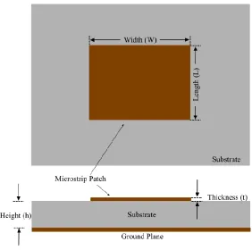
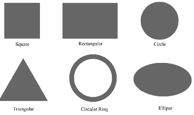
3.1 Microstrip Patch Antenna ... 38
viii | P a g e
3.2.1 Transmission Line model ... 41
3.2.2 Cavity Model ... 44
3.2.3 Full-wave Model ... 47
3.3 Radiation Conductance... 47
3.4 Input Impedance... 48
3.5 Fringing effect... 49
3.6 Antenna Parameters ... 51
3.6.1 Return Loss and VSWR ... 51
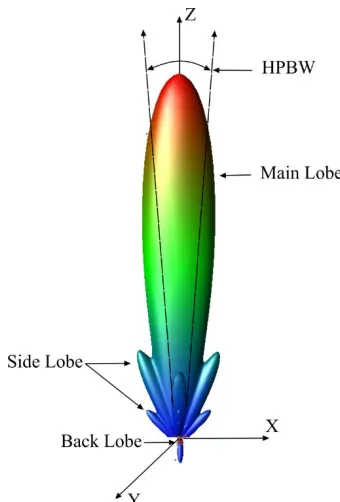
3.6.2 Radiation Pattern ... 52
3.6.3 Gain... 54
3.6.4 Bandwidth ... 55
3.6.5 Input Impedance ... 55
3.6.6 Polarization ... 57
3.7 Antenna Array ... 58
3.8 Microstrip Antenna Feeding Techniques ... 61
3.9 Summary ... 63
Chapter 4 : DESIGN OF A SINGLE PATCH ANTENNA ... 64
4.1 Dielectric material Selection... 64
4.2 Synthesized Dielectric Constant ... 67
4.3 Design Specifications ... 69
4.4 Design Procedure... 72
4.5 Single Patch Design Calculations ... 80
4.6 Summary ... 82
Chapter 5 : ANTENNA ARRAY AND DESIGN COMPARISON ... 83
5.1 Design Procedure... 83
5.2 Simulation results ... 86
5.3 Comparison with published results ... 89
5.5 Summary ... 90
Chapter 6 : FABRICATION ... 91
6.1 Top Wafer ... 91
6.2 Bottom Wafer ... 96
6.3 Wafer Bonding... 99
6.4 Summary ... 100
Chapter 7 : CONCLUSIONS ...101
ix | P a g e
7.2 Future Work... 103
APPENDIX ...104
Appendix A ... 104
Appendix B ... 109
Appendix C... 111
REFERENCES ...113
x | P a g e
LIST OF FIGURES
Figure 1.1 Applications provided by Driver Assistive Systems. ... 6
Figure 1.2 Phased antenna array. ... 11
Figure 1.3 Automotive radar system developed comprises of an antenna which utilizes a Butler Matrix. ... 12
Figure 1.4 Experiment set up with corner reflectors to understand the effectiveness of a large bandwidth ... 14
Figure 1.5 Comparison of two radars with (a) 0.5 GHz bandwidth and (b) 4 GHz bandwidth respectively [28]. ... 15
Figure 2.1 Analog Beamforming. ... 26
Figure 2.2 Digital beamforming network... 28
Figure 2.3 Eight input and eight output port Butler Matrix. ... 29
Figure 2.4 Rotman Lens... 31
Figure 2.5 Butler Matrix with Microstrip Aperture Coupled Antenna Array. ... 33
Figure 3.1 Microstrip Antenna top and cross-sectional view... 39
Figure 3.2 Microstrip antenna patch geometry ... 40
Figure 3.3 Effective dielectric constant and fringing effect [63] ... 42
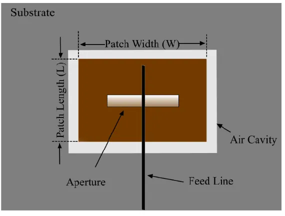
Figure 3.4 Aperture Coupled Microstrip Antenna Geometry. ... 43
Figure 3.5 Transmission Line model with two rectangular slots [23]. ... 44
Figure 3.6 Cavity Model Charge distribution [63]. ... 44
Figure 3.7 Equivalent circuit transmission line model of a simple microstrip patch [23]. ... 48
xi | P a g e
Figure 3.9 Length of the patch increased due to the fringing effect. ... 50
Figure 3.10 Radiation pattern of a directional antenna. ... 53
Figure 3.11 Microstrip Aperture coupled Antenna showing (a) cross-sectional and (b) top view of the feed lines. ... 56
Figure 3.12 Linear Polarization. ... 57
Figure 3.13 Circular Polarization (a) RHCP and (b) LHCP. ... 58
Figure 3.14 Linear Antenna Array. ... 60
Figure 3.15 Planar Antenna Array. ... 61
Figure 3.16 Different feed techniques (a) inset feed (b) stripline feed (c) coaxial feed and (d) aperture coupled feed. ... 62
Figure 4.1 Directivity vs dielectric constant. ... 65
Figure 4.3 Radiation pattern (a) with a cavity (b) without a cavity. ... 68
Figure 4.4 A single antenna element after the cavity was etched. ... 69
Figure 4.5 DRIE process, (a) top wafer DRIE etching of BCB (b) Deposition of a layer of gold for feedlines and a layer of BCB as feed dielectric (c) deposition of a layer of gold for ground plane and pattern it for aperture (d) thermos compressive bonding of top and bottom wafer ... 72
Figure 4.6 (a) top view and (b) crossectional view of the proposed antenna. ... 73
Figure 4.7 Comparative study between the directivity achieved with or without a dielectric cavity in BCB. ... 74
Figure 4.8 Varying lengths of the microstrip patch causes the change in resonant frequency (a) length increases and (b) decreases.. ... 75
xii | P a g e
Figure 4.10 S11 of a single antenna element with and without a cavity. ... 81
Figure 4.11 Radiation pattern of a single antenna element in (a) azimuth and (b)
elevation planes... 82
Figure 5.1 Polar Plot shows the effect of the number of patches on antenna
directivity. ... 84
Figure 5.2 Different gains achieved by changing the number of rows of patches.
... 85
Figure 5.3 Antenna array designed for the application in tri-mode radar... 86
Figure 5.4 S11 of the designed microstrip aperture coupled antenna array. ... 87
Figure 5.5 Radiation pattern of the antenna array (a) Elevation plane (b)
Azimuthal plane. ... 88
Figure 6.1 Formation of top patches using Lift of Resist technique theoretically
simulated in Intellifab™... 92
Figure 6.2 Formation of top patches using Lift of Resist technique simulated in
Intellifab™... 92
Figure 6.3 BCB deposited on the top of Au patch. ... 93
Figure 6.4 BCB deposited on top of Au patch simulated in Intellifab™... 93
Figure 6.5 Alteration and Lithography of back cavities for DRIE etch theoretical
representation ... 94
Figure 6.6 Alteration and Lithography of back cavities for DRIE etch simulation
executed in Intellifab™ ... 94
Figure 6.7 DRIE cavity formation in BCB. ... 95
xiii | P a g e
Figure 6.9 Strip photoresist... 95
Figure 6.10 Strip Photoresist simulated in Intellifab™ ... 95
Figure 6.11 Preparation of Pyrex wafer ... 96
Figure 6.12 Preparation of Pyrex wafer simulated in Intellifab™ ... 96
Figure 6.13 Deposition of Cr and Au for feed lines ... 96
Figure 6.14 Deposition of Cr and Au for feed lines simulated in Intellifab™ ... 97
Figure 6.15 BCB was spin coated on the Au feed lines ... 97
Figure 6.16 BCB spin coating simulated in Intellifab™ ... 98
Figure 6.17 Preparation of Au ground plane with an aperture in it. ... 98
Figure 6.18 Preparation of Au ground plane and aperture modeled in Intellifab™. ... 98
Figure 6.19 Wafer bonding a theoretical representation... 99
Figure 6.20 Cross-sectional view of wafer bonding. ... 99
xiv | P a g e
LIST OF TABLES
Table 1.1 WHO report on road traffic injury [3]... 3
Table 1.2 Atmospheric attenuation at 70-80 GHz [12] ... 5
Table 1.3 Principal Results ... 18
Table 2.1 Radar Classifications [47] ... 34
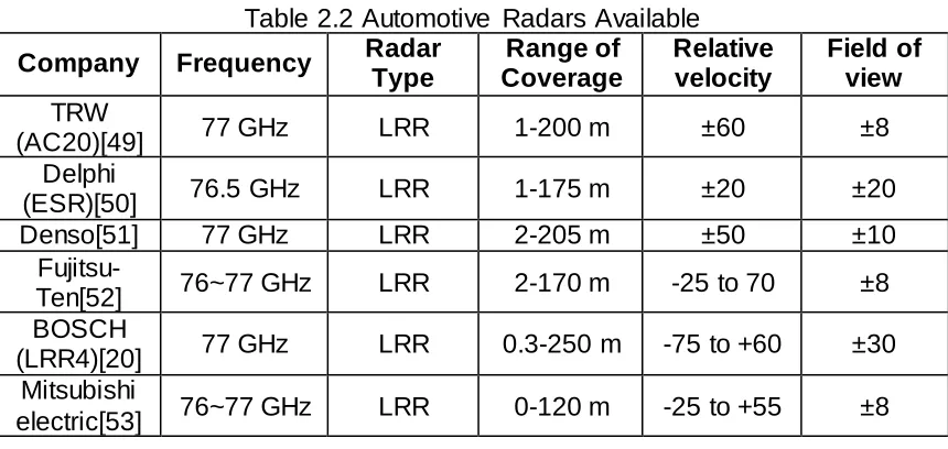
Table 2.2 Automotive Radars Available ... 36
Table 2.3 State-of-the-art antenna arrays for automotive radars ... 37
Table 3.1 Comparison of Various Feeding Techniques [23] ... 62
Table 4.1 Comparison of Normal and Micromachined Substrates [63] ... 67
Table 4.2 Specifications of a single element ... 80
Table 4.3 Dimensions of a single antenna element... 81
Table 5.1 Antenna Array Results ... 89
Table 5.2 Comparison against published results ... 89
Table 6.1 Process Parameters for deposition of Au ... 92
Table 6.2 Etching parameters for Au ... 92
Table 6.3 BCB deposition parameters ... 93
xv | P a g e
LIST OF APPENDICES
1. Appendix A: Matlab codes for Antenna Development
2. Appendix B: Mask files for Fabrication
xvi | P a g e
ABBREVIATIONS
3D – Three Dimensional
ADC – Analog to Digital Converter
ADS – Advanced Design Systems
Au – Gold
BCB – Bisbenzocyclobutene
BW – Bandwidth
Cr – Chromium
DAC – Digital to Analog Converter
DBF – Digital Beam Forming
DSP - Digital Signal Processing
DRIE – Deep Reactive Ion Etching
EM – ElectroMagnetic
FMCW – Linear Frequency Modulated Continuous Wave
FOV – Field of View
HPBW – Half Power Beam Width
IF – Intermediate Frequency
LIDAR – Light Detection and Ranging
xvii | P a g e
MEMS – Microelectromechanical Systems
MRR – Mid Range Radar
NHTSA – National Highway Traffic Safety Administration
Radar – Radio Detection and Ranging
RF – Radio Frequency
RIE – Reactive Ion Etch
RX – Received Signal
Si – Silicon
SRR – Short Range Radar
TEM – Transverse Electro Magnetic
TX – Transmit Signal
VCO – Voltage-Controlled Oscillator
xviii | P a g e
NOMENCLATURE
h
f
= Upper frequency of the -10dB emission pointl
f
= Lower frequency of the -10dB emission pointp
L
= Length of patchp
W
= Width of Patcheff
L
= Effective length of patchr
= dielectric constanteff
= effective dielectric constantc
= speed of lighto
f
= frequency of observationp
h
= height of patch dielectricf
h
= height of feed dielectricL
= Patch length increased due to fringing fields
= wavelengthtan = loss tangent
d
xix | P a g e c
Q
= Quality factor = skin depth of conductor
c
P
= conductor lossr
P
= power radiated from patch0
= wavelength in free space = reflection coefficient
L
Z
= Load impedance0
Z
= Characteristic impedanceG = Gain
= radiation efficiencyD = Directivity
AF = Array Factor
N = number of elements
planar
AF
= Array factor for a planar arrayk = wave number
xx | P a g e
synth
= synthesized dielectric constanteq
h
= equivalent heightmaterial
h
= material heightair
h
= air height0
V
= incident voltage0
V
= reflected voltagec
Q
= conductor quality factorT
Q
= antenna quality factord
Q
= dielectric quality factorT
1 | P a g e
Chapter 1 :
INTRODUCTION
In this thesis, a BCB based aperture coupled microstrip antenna array for
autonomous vehicle radar is presented. The antenna array can be utilized for
short (SRR), mid (MRR) and long range (LRR) radar applications like parking
assist, collision avoidance, and cruise control. The antenna array provides a
large bandwidth of 4.2 GHz which increases the range resolution capacity of the
radar and satisfies the requirements set out by the automotive radar industry.
This chapter provides a background of the project, motivation, the objective and
state of the art research work in the field of radar antennas for autonomous
driving. It stresses the importance and achievements of the past and ongoing
work in this domain. The chapter starts with a brief description of road safety and
accident records in the world with a highlight on North America.
The Chapter emphasizes the potential benefits of the antenna array currently
being developed at the University of Windsor and how it outperforms most other
radar antennas available in the market today.
1.1 Problem Statement
Automotive safety has been a widely sought after topic over the years and
ensuring a safer travel lead to progress from using simple seatbelts and airbags
to advance telematics systems that provide crash notifications. The automakers
have developed advanced technologies which not only mitigate the chances of
2 | P a g e
deployment of airbags, locking of seat belts etc. even when a crash occurs. From
collision avoidance to cruise control the automakers have developed systems to
keep an occupant of the vehicle safe from injuries and damage to property while
providing necessary comfort in driving. Existing technologies like LiDAR,
cameras, ultrasonic sensors, infrared, and radar often fall short of establishing a
safety shell around a vehicle due to adverse climatic conditions, system
architectural failure and even lapse of concentration while driving. Automakers
find it extremely difficult to manufacture these technologies with a robust design
capable of functioning at a varied temperature across the world at a reasonable
price. Thereby the situation of road safety falls sharp considering the reasons
stated.
About 40,000 people died in the USA in the year 2016 which is a precise 6% rise
in the death toll from the year before. The National Highway Traffic Safety
Administration (NHTSA) reported that there were 17,775 casualties on the road
in the first half of the year with a 10.4% increase from the same period previous
year [1] Although the fatality rates per vehicle registered and per vehicle distance
travelled has decreased since the advent of significant driver regulations but the
increase in the number of fatalities is directly due to the rise in vehicle uses and
the population in general. However, a sharp rise in fuel prices and driver
behavioral change has reduced the fatality rates to below the 1961 fatality count
[2]. Proper law enforcement on the roads has played a key role in maintaining
3 | P a g e
Table 1.1 is from the World Health Organization on road traffic injury [3]. It gives
out a detailed list of the fatalities according to the regional classification of the
World Bank, occurred through the years and offers a forecast for the future.
Western countries like the United States, Canada and Western and Central
Europe have been listed as high-income countries in table 1.1.
Table 1.1 WHO report on road traffic injury [3]
Different Regions
Number of Countries
Yearly fatalities in
thousands Change
(% ) 2000-2020 Fatality rate (death/100000 people)
1990 2000 2010 2020 2000 2020
East Asia and Pacific
15 112 188 278 337 79 10.9 16.8
East Europe and Central Asia
9 30 32 36 38 19 19.0 21.2
Latin America and
Caribbean
31 90 122 154 180 48 26.1 31.0
Middle East and North Africa
13 41 56 73 94 68 19.2 22.3
South
Asia 7 87 135 212 330 144 10.2 18.9
Sub-Saharan Africa
46 59 80 109 144 80 12.3 14.9
Sub total 121 419 613 862 1124 83 13.3 19.0 High
Income countries
35 123 110 95 80 -27 11.8 7.8
4 | P a g e
The global automotive market is expected to reach US $12.16 billion by 2025,
growing at a compound annual growth rate (CAGR) of 20.8% accordi ng to a
study conducted by The Report, Inc. [4]. The growth of this industry is primarily
due to the high demand for active safety features, innovations in the radar
technology, decreasing the prices of components and the increasing sale of
vehicles around the world. Advanced driver assistance (ADAS) systems like
radar, LiDAR, ultrasonic, and cameras help provide effective applications like
adaptive cruise control [5], pedestrian detection system [6], blind spot detection
[7], automated emergency braking and collision warning [8] and parking [9].
However, some of the devices used in the process lack the ability to work in a
varied temperature range and climatic conditions thereby bringing the issue of
safety again under considerable doubt. Radar devices are better opted than
LiDAR’s or cameras as they can work in adverse climatic conditions like heavy
snow, fog or rain with little to no effect in their performance of detection. A LiDAR
uses pulsed laser light which fails to perform adequately in rain, fog and snow
since when used under rain sizable fraction of points from the ground goes
missing due to the laser rays being reflected from reflective ground surfaces.
Heavy rains cause spurious LiDAR signal returns from plumes of rainwater from
cars while in foggy conditions there is significant creation of spurious returns from
car exhausts [10]. In heavy snow, the LiDAR fails to perform as the pulsed laser
light gets refracted due to the high refractive surfaces of snow [11]. While a radar
is much suited to adverse conditions as there is little to no effect in the
5 | P a g e
shows the amount of attenuation of electromagnetic signal energy between
70-80 GHz which indicates that radar technology is much suited to all weather
conditions, unlike their LiDAR counterparts.
Table 1.2 Atmospheric attenuation at 70-80 GHz [12]
Conditions Precipitation (mm/hr) Attenuation (dB/km)
Clear, dry air 0.00 0.1
Drizzle 0.25 0.2
Light Rain 1.25 0.5
Medium Rain 12.50 1.5
Heavy rain or Snow 25.00 9.0
“Radar technology is the key to building innovative driver assistance systems to
help avoid automobile accidents”, says Hans Adlkofer, Vice President and
General Manager of Infineon Technologies Sense and Control business unit [13].
Despite the fact that the radar technology first appeared in luxury cars, crash
prevention radar systems have made their way down to more reasonably priced
vehicles in the present days. This has created a positive competition between
automakers and is heading for a huge growth for the market of automotive safety
and driver assistance device markets. D. Hoetzer et al. [14] claims that by
installing crash prevention system in vehicles the number of accidents can be
reduced by 3.8 million in North America alone, with approximately 17000 lives
saved in the process every year. This emphasizes the requirement of radar
technology to ensure highway safety while minimizing loss of lives and property
6 | P a g e
1.2 Motivation
Automotive radar is used to detect the proximity of other vehicles and obstacles
to initiate actions to prevent and or minimize the loss of lives and damage to
property. These radar devices are classified into three different aspects
according to the range of coverage. The automotive industry has set various
radar standards depending on distance covered by the radar to the angular
sector scanned by the radar, pulse type, frequency modulation techniques, etc.
[12]. An automotive radar is typically divided into three types mainly on the basis
of the range and the application it serves. Figure 1.1 shows a vehicle with
different applications provided by driver assistance systems installed in it for
safety.
Figure 1.1 Applications provided by Driver Assistive Systems.
The advantages provided by these radars resulted in an increase in their
installation in the vehicles worldwide. Various automotive radar systems are
available in the market which produces various applications listed below:
7 | P a g e
Blind spot detection.
Adaptive cruise control systems with a support in a cut in and Stop & Go situations
Pre-crash detection.
Since its inception in the early 1900’s when the first patent on the automotive
radar [15] was published a lot of research work has been thoroughly undertaken
in this domain to constantly upgrade the level of technology and ease its
integrability with the vehicle. The criteria set by the automakers for such devices
are small, robust and cheap while providing effective performance across all
climatic conditions.
Since the 90s the 77 GHz frequency domain has been opted for the automotive
long range radars [16] as it provides excellent performance in range and azimuth
angle coverage with producing a narrow beam for long-range applications. In
addition to the advantages listed earlier for the 77 GHz frequency allocation, it
also helps provide a better resolution since it increases the bandwidth availability
in the domain and reduces the chances of signal interference from other devices
working in a domain near it. Lower frequency domains like 24 GHz were
previously utilized for shorter ranges since it would produce a wider antenna
beam; however, the bandwidth allocated for those frequency bands were small
which would provide a smaller range resolution while there was a high possibility
of signal interference from other devices operating in a frequency near it. The
authors in [17] reported that millimeter waves at higher frequencies, i.e. at 77
8 | P a g e
penetration through the human skin. An average thickness of human skin lies
somewhere between the 0.5 mm (on the eyelids) and 4 mm (on the palms) [18]
while the penetration depth of the millimeter waves was under 0.5 mm at 77 GHz
compared to twice of it in the 24 GHz frequencies. The authors in [17] also
revealed that about 40% of the incident power gets reflected from the skin
surface at 60 GHz. Therefore, at higher frequencies the damage to human
tissues are less compared to the lower frequency band of 24 GHz previously
allocated. Hence the technology drifted towards the 77 GHz where the bandwidth
of 1 GHz was allocated between 76 and 77 GHz. Upon further advancement of
technology, the European Commission initiated the 79 GHz project for vehicular
radars. The new frequency band would work with an even wider bandwidth of 4
GHz between 77 to 81 GHz for shorter ranges and a target resolution level would
be brought down to a few millimeters [19]. However, for the long and midranges,
the 77 GHz band is still preferred which provides a range resolution of about a
meter. Another point is that as the operating frequency increases, the guided
wavelength g defined as / r where is the free space wavelength and r
is the dielectric constant of the antenna substrate decreases. As the antenna
patch dimensions are directly related to the guided wavelength, a decrease in the
guided wavelength results in a decrease in the patch dimensions to contribute to
a decrease in the overall radar size.
1.3 Existing Solutions and their Limitations
Various automotive radar developers like Continental™, BOSCH™, Mitsubishi
9 | P a g e
and have been constantly providing auto manufacturers with sophisticated radar
modules at cost-effective rates. BOSCH™ has upgraded its radar module from
the first generation to the fourth generation [20] with a constant improvement of
radar performance throughout its journey as a radar developer. Other
companies, such as Delphi™ and Denso™ has also produced such modules
which are in high demand in the market. However, search for a cheaper product
which outperforms other the devices in the market is always desirable and
sought after.
Many radars available in the market today offer a smaller range resolution which
often leads to the failure of a proper detection of the proximity of the obstacles
around the vehicle in shorter ranges as the number of samples generated per
second is less when the bandwidth offered by the radar is less [21]. The
requirement set forth by the auto industry are not often met at reasonable prices
as the expense rendered for manufacturing components increases. Some radar
modules offer shorter ranges than the requirements while some even produce
false alarms.
Cost effective substrates like Rogers 5880, 3003 [22] have been thoroughly
explored over the years for providing a high performing antenna. While these
dielectrics helped increase the quality of performance for the products
manufactured, the process of integrating the antennas with its signal processing
modules became increasingly challenging.
In 2012, [23] Ismail et al designed a radar antenna on a silicon substrate which
10 | P a g e
provide high performance but at the cost of an increased price of production in
mass scale. In 2013, [24] designed a radar antenna which was a complete
package except it was large in size about 5 cm by 2 cm. A lot of advancement
has been made in this domain but not a proper solution has been reached which
would offer to solve the problem at hand. In 2017, [25] produced a radar antenna
at 77 GHz which had a high gain expected to cover 300 m for long-range
applications however the bandwidth of the antenna was extremely narrow with a
very low reflection coefficient and the size of the antenna array was huge.
Hence, the target of this thesis is to present a smaller sized radar antenna
capable at providing a wider bandwidth with higher gain and directivity to cover
the range requirement while manufactured at a lower overall cost price.
1.4 Electronically Scanned MEMS Radar
Each radar system is a unique device which is capable of identifying its own
signal echoes through the Doppler shift of their radar signatures. A radar is
provided with an LFMCW signal which frequency modulates the carrier wave of
the device and thereby producing a unique signature for every radar module
manufactured. Electronically scanned antenna arrays are extremely beneficial for
facilitating radar sensors for various applications like military and broadband
communications. The most important feature of an electronically scanned
antenna is the phased antenna array system. The phased array system works on
the principle of creation of a single beam which is electronically steerable from
phasing the individual antenna elements. This single beam is electronically
11 | P a g e
radiating antenna element. A linearly phased array with equal distance between
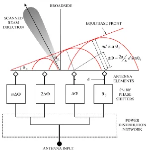
elements is a most desired design form as it is easy to analyze. Figure 1.2 shows
a basic electronically beam steerable antenna array module with an inter-element
spacing of d between them. By altering the phase and the amplitude of excitation
of each element, the direction and the shape of the beam radiated from the
antenna array can be easily controlled. The phase excitation
n controls theangle of the directed beam,
0 in a phased array. To produce a broadside beamof
0
0
the phase excitation should be
n0
.12 | P a g e
Other scan angles require an excitation,
nnkd
sin
0, for the nth elementwhere k
2
is the wave number. These electronics actively utilize theconcept of a phase shifter which increases the circuit complexity and the price by
a margin of a thousand dollars or even more [26] [27]. A method to lower the cost
of these radars is to utilize microelectromechanical systems, the approach in
batch fabricating these devices on an inexpensive material and eliminate any
circuit complicacy due to phase shifters. Options like Butler Matrix and Rotman
lens which are beamforming beam steering networks offers cheap and compact
means to extend single beam systems to a fully functional beam steerable
devices. Use of MEMS technology for hardware modules reduces the circuit
manufacturing overhead.
13 | P a g e
Not only a beam steering module can be included in the circuitry but also the
whole antenna array can be included in a single substrate. This greatly reduces
the packaging and interconnect complexity thereby reducing the overall cost. A
block diagram for this radar is shown below in figure 1.3. Depending on the range
of coverage, the radar antenna’s radiation pattern must have a narrow
beamwidth of a few degrees, higher bandwidth with lowered sidelobe levels and
high radiation efficiency to obtain effective performance while providing low cost
for manufacturing. In this context, this thesis presents the design of a highly
directive planar antenna on a benzocyclobutene substrate for automotive radar
applications. The radar is expected to fulfill the mid and long range requirements
set by the automotive radar industry. The advantage of this design is that it
allows easy integration to the transceiver modules unlike other dielectrics and
also produces a higher bandwidth thereby allowing a better range resolution.
Long distance radars require a large high gain antenna and one of the objectives
of this research work is to reduce the dimension of the device while providing an
optimum amount of gain for the target application. At millimeter wave frequency,
the usage of mechanically scanned antennas experiences a slow response and
suffers from false alarm due to shock and vibration, while on the other hand
antennas with phase shifters are extremely expensive to manufacture and initiate
considerable RF losses. By using an innovative technique of utilizing a Rotman
14 | P a g e
1.5 Benefits of wide bandwidth in Long Range Radars
Automotive radars generally opt for wide to narrow bandwidths depending on the
range of their functionality. Traditionally short and mid-range radars with a wider
bandwidth are preferred to improve resolution and enhance detection of nearby
obstacles. However, a longer range radar functionality can also be enhanced
with the improvement of the bandwidth from a narrow band to a wider one [28].
This is due to the fact that a wider bandwidth facilitates detection of smaller sized
moving objects effectively. Pedestrians have a comparatively smaller radar cross
section and tend to change directions often. Hence a higher resolution radar
helps keep track of the sudden direction changes and helps to avoid collisions by
facilitating the detection of the pedestrians [28]. On the other hand, a single radar
unit with a 4 GHz bandwidth can be used in a multimodal implementation without
any significant change of hardware.. A simple experiment was conducted to
produce the effective resolution necessary for mid and long range vehicular
applications by placing a set of corner reflectors as targets for a radar [28].
Figure 1.4 shows an experimental set up of the designed targets.
15 | P a g e
The radars with a 0.5 GHz bandwidth detected only a single corner reflector kept
0.5 m apart while the radar with a 4 GHz bandwidth was able to detect both the
target. Figure 1.5 graphically presents the outcome of the experiment done in
[28].. Hence, 0.5 m has been set as a standard for mid and long-range radar
resolutions. Apart from a higher resolution, the detectable range is an important
criterion for radar modules as a wider detectable range reduces the number of
automotive radars mounted for fully autonomous driving [28].
Figure 1.5 Comparison of two radars with (a) 0.5 GHz bandwidth and (b) 4 GHz bandwidth respectively [28].
1.6 Research Objectives
Design an antenna array for the automotive radars functioning at long and mid
ranges with the following target specifications to satisfy the auto industry
roadmap [16]:
An antenna array with a higher gain (~20 dBi) and directivity to meet the range requirement of 200-250 m.
An antenna array with wider bandwidth (~4 GHz) for better range resolution.
16 | P a g e
Design an antenna which would be robust and capable of functioning at a varied temperature range (-40 - 85º) [29] as set forth by the auto industry.
Design the antenna with cheaper materials which can be easily manufactured in mass scale production.
Utilize materials which would ensure the antenna does not suffer from the problem of integration with its signal processing modules.
1.7 Proposed Solution and Hypothesis
Various antenna studies over the years have revealed that low k dielectric
materials are better suited for automotive radars as they provide better insulation
and hence a higher gain and bandwidth. Dielectric materials like Rogers 5880,
Rogers 3003 [30] [22] have been thoroughly utilized by modern day antenna
developers for their obvious benefits of low k values. However, the designs fell
short because of considerable complexity in establishing a robust connection
between the antenna arrays and other radar components. Hence researchers are
always in search of a material which can mitigate this problem at the lowest cost
available.
In this thesis, a low-k dielectric derived from B-staged bisbenzocyclobutene
(BCB) monomers commercialized by the Dow Chemical Company under the
trade name Cyclotene 3000™ has been investigated as the dielectric material to
realize an high gain wider bandwidth microstrip antenna array for automotive
radar. Investigation by [31] and [32] show that the dry etchable BCB (Cyclotene)
with a dielectric constant of 2.65 can be batch fabricated using conventional
17 | P a g e
with the radar transceiver module, realizing the necessary gain and bandwidth
within a small footprint of an automotive radar is still a big challenge.
Various research works have been reported where several stacked layers of
dielectric materials were used to achieve an effective dielectric constant for the
antenna which is lower than the dielectric constant of any individual layer [33].
The authors in [33] experimentally have shown that introducing an air filled cavity
in a microstrip antenna where high resistivity silicon has been used as the
antenna dielectric material can result in an effective dielectric constant of
approximately 1 as compared to 11.8 if only a layer of high resistivity silicon was
used. This study confirmed that when a material with a higher dielectric constant
(e.g. silicon) is placed in parallel to a layer of lower dielectric constant material
(e.g. air), the dielectric constant of the combined structure gets reduced.
However, other studies have revealed that the volume of each material also
plays an important role in determining the new synthesized value. In order to
decrease the dielectric constant of the layer of BCB underneath the radiating
patch, an innovative air-filled cavity has been introduced in the BCB layer using
an deep reactive ion etching (DRIE) method.
This thesis would provide a detailed understanding that how etching a cavity in a
layer of dielectric can improve the performance of the antenna modules.
1.8 Principal Results
A DRIE cavity etched microstrip aperture coupled antenna array for use in 77
18 | P a g e
array has a foot print area of 20 x 21 mm2 to accommodate 56 micorstrip patches
in a 7 x 8 matrix configuration. Each of the gold patches has a length of 1.46 mm
and a width of 1.7 mm. The anteena array exhibits an ADS™ (Advanced Dsign
Systems) 3D simulated -10 dB bandwidth of 4.2 GHz, 22.5 dBi directivity, and a
gain of 19.78 dBi with sidelobe levels lower than 13.78 dB to meet the auto
industry roadmap reccommendations. A fabrication process table has been
developed and simualated successfully using IntelliSuite™, an industry standard
software. The developed process table can be used to fabricate the device. The
vast bandwidth produced by the antenna array results in its direct application in
the short-range radar which requires higher range resolution while the highly
directional beam with high gain in the broadside direction ensures its usage in
the longer ranges in applications like cruise control and collision avoidance.
Table 1.3 contains the achieved simulation results of the proposed antenna
array.
Table 1.3 Principal Results
Parameters Results
Gain 19.78 dBi
Azimuth Angle tilt 0º Elevation Angle tilt 8º
Angle of Opening ±5.5º
Bandwidth 4.2 GHz
Radiation Efficiency 45%
VSWR 1.04
1.9 Thesis Outline
Chapter 1 provides a review of the state-of-the art in automotive radars and their
19 | P a g e
crash damage. This chapter also provides road crash statistics of the World
Health Organization and the fatality rate in North American and European
countries.
Chapter 2 briefly summarizes the existing literature of automotive radar antenna
array technologies. This chapter provides a background about a MEMS-based
radar system and its usefulness in the developing automotive radar technology.
Chapter 3 presents a detailed modeling and design strategies of a microstrip
antenna. It includes all the essential parameters needed to design a microstrip
antenna. This chapter also provides brief details about various antenna design
parameters on which an antenna performance is judged. Linear and planar
antenna array design methodologies are discussed in this chapter.
Chapter 4 provides details about the importance of a micromachined substrate
and how lowering the dielectric constant of the substrate beneath a microstrip
patch effects the overall antenna performance. It provides detailed information on
design methodology and simulations undertaken to design a single antenna
element.
Chapter 5 provides details on the design of the antenna array by using single
elements in conjunction to obtain the necessary results for the radar antenna. It
provides detailed insight into the antenna array design and simulations
undertaken to obtain the targets set before the thesis. It has a comparison with
other published results on automotive radar antenna arrays operating in the
20 | P a g e
Chapter 6 makes the concluding remarks of this research work and provides
some remarks on the future directions to extend the performance of the current
21 | P a g e
Chapter 2 :
REVIEW OF LITERATURE
This chapter reviews the state-of-the-art in automotive radar systems and
associated antenna array modules. The drawbacks of existing technology are
highlighted and the reasons for developing a new design are emphasized.
2.1 Review of Literature
Roads around the world are shared by cars, buses, trucks, motorcycles, mopeds,
pedestrians, taxis and other categories of vehicles. Travel is made possible by
motor vehicles which support economic and social development in many
countries. Due to the ever increasing population, road safety has evolved into a
serious issue with a sharp rise in vehicle demand all around the world. Statistics
published in June 2017 showed that in a developing nation like India there was
over 210 million registered vehicles in the year 2015 [34]. While in a developed
nation like the US the numbers exceeded 253 million among cars and trucks
around with an increase of 1.5% from the year before in 2014 [35]. Due to the
increase in on-road vehicles, highway safety, and intercity travel becomes a huge
challenge for the people living around the world.
It is reported that each year approximately 1.25 million people are killed on
roadways around the world. Each day an estimated 3400 people are killed
globally in road traffic crashes involving cars, buses, motorcycles, bicycles,
trucks or pedestrian. Half of the number of fatalities involved pedestrians,
22 | P a g e
injuries to be the eighth leading cause of death for young aged people between
15-29 years. Current trends predict that by 2030, road traffic injuries will amount
to 7% of the deaths worldwide [36].
Even though measures like seatbelts and airbags for crash prevention have been
used worldwide the scenario of road traffic comes under heavy scrutiny due to
the incompetence of these aforementioned devices to protect and provide
adequate safety. Hence auto manufacturers have advocated the use of ADAS to
minimize road accidents and ensure driver and passenger safety in all situations.
These ADAS systems include devices like radar functioning in different ranges,
cameras for rear and front viewing, ultrasonic transducers for blind spot detection
[37] and even LiDAR to assist the radar modules in shorter ranges depending on
their intended application.
Radar has the unique ability of instantaneously detecting the velocity and range
of the target objects via the Doppler shift of their radar signatures and can easily
function in adverse climatic conditions like rain, snow, fog, and hail, unlike LiDAR
and cameras. These specific benefits have driven the auto manufacturers to
adopt radar in increasing numbers. In the US, the NHTSA entered in an
agreement with 20 automobile manufacturers, representing more than 99 percent
of the automotive market to voluntarily equip all production vehicles with
Automatic Emergency Braking (AEB) Systems by 2022 [38]. As the vehicles
progress from manually driven ones equipped with ADAS systems to fully
autonomous driving the role of radar, LiDAR and cameras becomes increasingly
23 | P a g e
decisions. Future vehicles might include up to eight radar modules for a
360-degree coverage around a vehicle. [38]
2.2 Radar types
Depending on the requirements, a radar can use different techniques to generate
the transmitted signal and identify the received echoes. Previously the radar
systems were based on pulsed echo technology that required high power pulses.
Even with their advantages of measuring the ranges accurately by calculating the
time delay between transmitted and received signals, pulsed echo systems
suffered from a drawback of false alarm and were mainly blind in shorter
distances of (50-100 m) at the center of the radar. Continuous Wave radars
continuously transmit the RF wave at a lower power level (typically less than
50mW) and a selected frequency. The CW radar systems continuously observe
the return from a target over a period of time, commonly called the Coherent
Processing Interval (CPI). During the CPI, the instantaneous transmit and receive
signals are mixed, and the resultant intermediate frequency (IF) signal is
assessed over the CPI for valid targets. The CW radar technology is still under
constant refinement with new strategies related to both hardware and signal
processing algorithms being developed. There are two prime implementations of
CW radar: FH- (Frequency Hopping) or FSK-CW (Frequency Shift Keying) radar
and FM-CW (Frequency Modulated) radar. In FSK-CW the RF jumps between
multiple frequencies over a CPI, whereas FM-CW makes use of a frequency
24 | P a g e
The German Federal Ministry of Education and Research abbreviated as (BMBF)
funded the joint project “Automotive High-Frequency Electronics KOKON” [39]
was initiated (September 2004 - August 2007) due to the short range regulation
in Europe and a phased array frequency modulated continuous wave (FMCW)
systems with beamforming and beam steering capability became the technology
of choice for the forward ranging application. The FMCW technique is
advantageous as the received signal is a time-delayed copy of the transmitted
signal where the delay,t is related to the range. The received signal always sweeps through a frequency band at any moment during the sweep, the
frequency difference,
f
b (beat frequency) is a constant between the transmittedand the received signal. Since the sweep is linear one can derive the time delay
from the beat frequency and translate the delay into the range. Key advantages
provided by FMCW based phased array radar are:
Low power
Beam steering capability without mechanical rotation of the mounted base
Reduced clutter and phase noise
High precision in measurement of target range and velocity
More immune to interference from devices working in a similar frequency
No theoretical blind spot
2.3 Microelectronic beamforming
The beamformer is a device when used in conjunction with a sensor array helps
25 | P a g e
designed to direct the transmitted or received signal from an antenna array to a
chosen angular direction to realize spatial selectivity. When in transmitting mode
a beamformer directs the amount of phase and amplitude at each transmitter to
create a pattern of constructive and destructive interference in the wavefront,
while at receiving the information from different receiving sensors the information
is combined in a way where the expected pattern of radiation is preferentially
observed.
High directivity is often desired in communication systems, especially in
automotive radars, in order to establish a low noise high fidelity link to collect
ranging and velocity information in the direction of the signal source. In radar
systems, the beamforming allows a process of electronic steering of the highly
directive beam to detect targets with higher angular resolution. The beamforming
network controls the phase and amplitude of the signal at each transmitting
element in order to form a pattern of constructive and destructive interference in
the wavefront.
2.4 Types of Microelectronic Beamforming
Microelectronic beamforming is a process of both generation and steering of a
directional pattern of the main lobe in the azimuth and elevation planes and can
be categorized in two different modes:
Analog beamforming:
Analog beamforming refers to the combination of the received signals from each
element at a carrier frequency level. Beamforming controls both the amplitude
26 | P a g e
phase and amplitude control can facilitate better adjustment of side lobe levels
and steer nulls to minimize false alarm and no detection.
In a beamforming network, the signals fed at each individual element are
combined methodically through electronic means to form a single desired
beamformed output. Before the incoming signals are formed, they are brought
down to baseband or intermediate frequencies. Receivers connected at the
output of individual element perform the necessary frequency down conversion.
Hence it becomes imperative for the digitization of the down-converted signal
before they are processed. Analog to Digital Converters (ADC) are connected to
the outputs for this purpose. For accurate performance, they are required to
provide an accurate translation of the RF signal from analog to digital domain.
Auto manufacturers like BOSCH™, Delphi™, TRW™, Fujitsu Ten™, and
Denso™ have all used the analog beamforming technology in their 77 GHz Long
Range Radars. Other manufacturers like Mitsubishi electric™ and Celsius
Tech™ used mechanical mechanisms in conjunction with ADCs to steer the
beam in azimuth. [16]
27 | P a g e
Digital beamforming:
In Digital beamforming, the operations of phase shifting, amplitude scaling and
summation for receiving of individual antenna element are done digitally. Multiple
independent beams can be transmitted in all directions which can be steered are
formed in the digital beamforming processor. The benefits of digital beamforming
are:
o Multiple beams can be controlled
o Improved dynamic range
o Improved and faster control of phase and amplitude
Although the digital beamformer requires memory blocks, adders and multipliers
as system building blocks to function yet it is considered to be more efficient than
an analog beamformer [40]. Digital beamforming utilizes many digital receivers
that can be utilized. Converting to an intermediate frequency by digitizing the
signal is realized at each antenna element. Figure 2.2 shows a digital
beamforming network. In 2003 radar sensors with digital beamforming was
introduced in the market by Japanese companies. Denso built a bistatic LRR with
planar patch antennas with a range capability up to 150 m and a field of view of
28 | P a g e
Figure 2.2 Digital beamforming network.
Butler Matrix and Rotman lens beamforming:
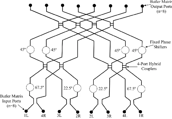
The Butler Matrix is a microwave network, normally employed in beamforming
and scanning networks for linear and circular antenna arrays [42]. This feed
network typically is in the form of Figure.2.3, which is an N input and N
connection. A Butler matrix can also have N inputs with N outputs. It comprises
of different hybrid junctions and phase shifters that can be implemented with
discrete microwave techniques such as waveguides and also as a microstrip
technique.
Main features of Butler Matrix are:
o The Butler matrix has 2n inputs and 2n outputs
o It has (N/2) log2 N hybrid junctions, where N=2n
o The outputs are Fourier transform of the inputs
o The schematic of the Butler Matrix is identical with the programming structure
29 | P a g e
Figure 2.3 Eight input and eight output port Butler Matrix.
If a Butler matrix is connected to an antenna array, the matrix will act so that the
array will have a uniform amplitude distribution and a constant phase difference
between neighboring elements:
exp(
jknd u
x i)
(2.1)For i
x
u i
Nd
. where
3 5
1 , , ,...
2 2 2
i for N even and i
0,1, 2,3,...
forN odd.
This results in radiation at one of N unique discrete directions covering a 180º
angular sector of space figure 2.3. The actual direction of the beams is
dependent on which one of the input the signal is introduced. The phase
difference between radiating elements for a Butler Matrix with N elements and
30 | P a g e
2 2 1
cos 180
n
d p
N
(2.2)
Where the phase difference,
n is plus or minus depending upon whether thebeam is to the right or left of the broadside respectively. Equation (2.2) depends
on
, therefore the beam anglesu
vary with frequency. The Butler matrix thusforms phase steered beams which squint with frequency. The beam cluster is
narrow for higher frequencies and broad for lower frequencies.
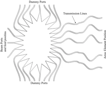
Rotman Lens: Much like the previously discussed Butler matrix, a Rotman lens
also offers an inexpensive and compact solution to extend the single beam
systems to fully beamsteering modules. The microstrip line flexibility and the fast
simulation packages allow the Rotman lens to be designed at millimeter
wavelengths. A Rotman lens offers beam steering and beamforming advantages
without any requirement of a microelectronic signal processing network unlike the
analog and digital beamforming networks. Figure 2.4 shows a Rotman lens
31 | P a g e
Figure 2.4 Rotman Lens.
2.5 Antenna Arrays
Antenna arrays play a crucial role as it acts as a radiating and receiving unit of
the radar systems. Planar antenna arrays can satisfy the automotive radar
market demands of low-profile, low weight and fast beam steering ability at a
lower cost. The antenna array parameters like gain, bandwidth, and radiation
efficiency mark the performance of the antenna array. Microstrip antennas are
traditionally preferred as radar antennas as they are light in weight, easily
manufacturable and also inexpensive. However, even with their benefits of
simpler low cost fabrication, the microstrip antennas are historically have been
recognized to provide lower gain. A gain of 8 dBi per patch is considered to be
standard in terms of performance provided by the antenna [44]. However,
32 | P a g e
dBi. It is extremely difficult to design an antenna with high gain, necessary beam
directivity and HPBW at the same time maintaining all specifications set by the
automotive industry. Hence, the auto manufacturers rely on antenna arrays
which is a group of similar radiating structures made to work in unison.
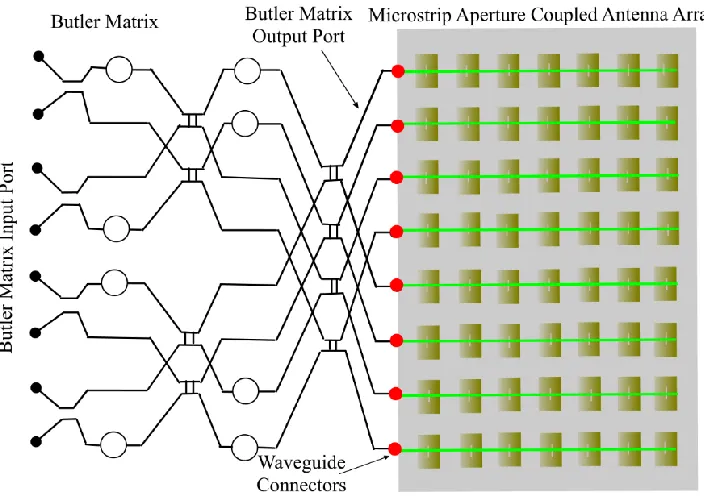
Modern effective techniques of utilizing a beam steering beamforming device like
Butler Matrix or Rotman lens can aid in steering the beam to the desired angle to
get an effective angular coverage as necessary for a specific safety requirement.
The Butler Matrix can help in directing the beams in different directions as
desired. In addition, the idea of utilizing a Butler matrix provides a uniform
amplitude distribution and the constant phase difference between the
neighboring elements while ensuring a low cost manufacturing. Thus the
combination of a Butler matrix and a microstrip antenna array can provide a high
performance low cost solution for multi range automotive radars. Figure 2.5,
presents the proposed Butler Matrix and the microstrip antenna array
33 | P a g e
Figure 2.5 Butler Matrix with Microstrip Aperture Coupled Antenna Array.
2.6 State of the art Automotive Radar
Since its first successful test in 50’s, the automotive radar manufacturers have
continued massive development and slowly have ventured into the microwave
frequencies. From 17 GHz to 24 GHz, systems slowly shifted their operating
frequencies and have ventured into 77 GHz with a prediction of systems working
at 79 GHz in the future years. The main reason for choosing a high frequency for
automotive radar application is due to the available bandwidth at higher
frequencies and the formation of the highly directive beam with lower HPBW at
higher frequencies necessary for long range applications like collision avoidance
and cruise control without any health hazard.
Even the short range radar industry has slowly drifted towards the 79 GHz