3
SMART ANTENNA BEAMFORMING
NETWORK
Sharul Kamal Abdul Rahim
Peter Gardner
3.1 INTRODUCTION
Smart Antenna with RF beamforming capability can greatly improve the performance of the vehicle communication system by providing better link quality and high immunity to interference. Butler Matrix is a well-known beamforming network. It can be used for multibeam antennas. The Butler Matrix increases the system capacity and provides higher signal to interference ratio, consequently enhancing the overall system performance.
Several studies have been conducted related to the cascading Butler Matrix. In an Multi Port Amplifier (MPA) application, a signal entering one port of the Butler Matrix is divided into equal parts. The signal is then amplified by all the amplifiers and then recombined by the combining Butler Matrix at the output port that corresponds to the particular input port.Suarez also reported that the introduction of the cascading Butler Matrices improves the performance of antenna parameters such as cross over and beam orthogonality.
input ports to regenerate the broad beam characteristics of the individual antenna elements. As a result, high linearity and broad beam signals are produced on the output ports of the second Butler Matrix while high gain and narrow beam signals are produced on the output of the first Butler Matrix.
3.2 DESIGN AND MEASUREMENTS
The configuration of the system consists of an array of dipole antennas with 0.5 λ (lamda) spacing, LNAs, Wilkinson power divider, HL_LNAs and two Butler Matrices as shown in Figure 3.1. From the figure, input ports are ports 5 - 8. The output ports from the second Butler Matrix are ports 1 - 4 while the output ports from the first Butler Matrix are port 9 - 12.
The system is operating at 2.45GHz. The LNAs, HL_LNAs, Wilkinson power divider and Butler Matrices are fabricated on FR4 substrate with dielectric constant of 4.4. The gain of the LNAs and HL_LNAs are approximately 17dB and 11dB respectively at 2.45GHz.
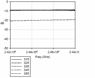
The Butler Matrix is a combination of 90˚hybrids, 0dB crossovers and phase shifters, used for beamforming because of its simplicity and easy fabrication. Figure 3.2 shows the measured S-Parameters of an individual 4x4 Butler Matrix when input port 5 is fed. From the figure, with the output ports defined as ports 1,2,3 and 4, the input return loss (S55) is less than –10dB in the 2.42- 2.48GHz bands. While the output responses (S15, S25, S35, S45) are about -8dB at 2.45GHz.
beam while the signals from the other ends of the Wilkinsons are fed to HL-LNAs to be amplified and recombined in the second Butler Matrix.
When compared to a system involving direct, single ended amplification of the individual antenna outputs this system offers enhanced linearity, because the outputs of the four high linearity amplifiers are power combined by the second Butler Matrix. Further, the effect of the loss of the Butler Matrix on the system noise figure is reduced with the introduction of LNAs before each stage of the first Butler Matrix. The effects of interference and cross coupling in this experiment are reduced because metal boxes are used to shield each of the modules.
Figure 3.1 The system configuration
3.3 EXPERIMENTAL RESULTS
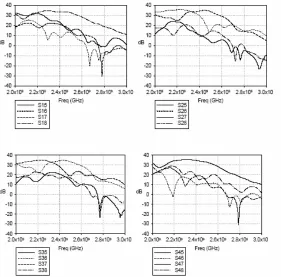
Figure 3.3 shows the output signals from Ports 1-4 for the broad beam system when input port 5-8 are fed with input signals. From the figure, output signals S18, S27, S36 and S45 clearly dominate. The signals are at least 10dB more than the outputs associated with the other input ports. The gain at these output ports is around 32dB at 2.45GHz. It clearly indicates that the four outputs from the second Butler Matrix will have beam patterns close to those of the individual array elements.
On the other hand, the measured S-parameter results from Figure 3.4 indicate that when an input port is fed with signal, four approximately equal output signals will emerge from the output ports of the first Butler Matrix. The gain at all the output ports from all the input ports is around 19dB. The difference of around 10dB between Figure 3.3 and Figure 3.4 is mainly due to the gain of the HL_LNAs after the Wilkinson power divider.
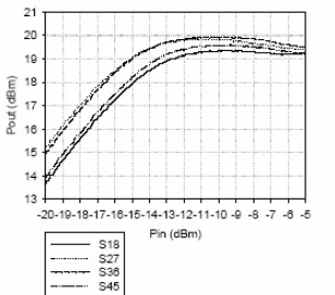
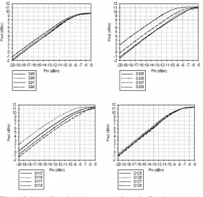
Figure 3.5 and Figure 3.6 show the linearity measurement of the receiver system. Figure 3.5 shows high linearity signals from the second Butler Matrix while Figure 3.6 shows the lower linearity signals coupled from the first Butler Matrix outputs. From Figure 3.5, 1 dB gain compression for these ports occurs at an output power of 19 dBm. While 1dB gain compression for the first Butler Matrix outputs occurs at the output power in the region of 10 dBm .
long distance communication while the broad beam can be used for shorter distance communication. The second Butler Matrix acts as a four-way power-combining network, which will create a nominal 6 dB improvement in linearity. The slight distortion of the broad beam shape on Figure 3.7b is probably due to the Butler Matrix phase shift error and cross coupling effects.
Figure 3.4 S-Parameter Measurement of a Single Butler Matrix
Figure 3.5 Non-linearity Measurement from the second Butler Matrix
Figure 3.6 Non-linearity Measurement from the first Butler Matrix
outputs
Figure 3.7 Radiation Pattern Measurement of the system (a) Narrow
3.4 CONCLUSIONS
Broad beam high linearity and narrow beam high gain signals are generated when passive elements such as the Butler Matrices are cascaded and integrated with the active elements such as the LNAs. At the output of the second Butler Matrix, large signals from sources close to the receiver are amplified with high linearity while signals from more distant sources have the benefit of high antenna gain at the output from the first Butler Matrix. This setup is potentially useful for vehicle applications when Inter Vehicle communication and Vehicle to Roadside communication are required simultaneously.
REFERENCES
Wincza, K.; Gruszczynski, S, “A Broadband 4x4 Butler Matrix for Modern-Day Antennas”, 2005 European Microwave Conference, Volume 2, Oct. 4-6, 2005.
Zak, T.; Sachse, K., “An integrated Butler matrix in multi-layer technology for multi-port amplifier applications”, 14th International Conference on Microwaves, Radar and Wireless Communications, 2002. MIKON- 2002, Volume 1, 20-22 May 2002.
Piovano, B.; Accatino, L.; Angelucci, A.; Jones, T.; Capece, P.; Votta, M, “Design And Breadboarding Of Wideband Nxn Butler Matrices For Multiport Amplifiers” Microwave Conference/Brazil, 1993, SBMO International Volume 1, August 2-5, 1993.
Angelucci, A.; Audagnotto, P.; Corda, P.; Piovano, B, “Multiport power amplifiers for mobile-radio systems using microstrip Butler matrices”, Antennas and Propagation Society
Sudrez-Fajardo, C.; Ferrando-Batallur, M.; Valero, A.; Rodrigo, V, “Multiple beam system with circular arrays”, Antennas and Propagation Society International Symposium, 2005 IEEE, Volume 4B, 3-8 July 2005.
Suarez, C.; Ferrando-Bataller, M.; Valero- Nogueira, A, “Pattern synthesis of uniform circular arrays with directive elements”, Antennas and Propagation SocietyInternational
Symposium, 2004. IEEE, Volume3, 20-25 June 2004. S.K.A.Rahim, P.Gardner, “Active Array and Beamformer SNR