Implementing BLAKE with AVX, AVX2, and XOP
∗Samuel Neves1and Jean-Philippe Aumasson2
1
University of Coimbra, Portugal 2 NAGRA, Switzerland
Abstract. In 2013 Intel will release the AVX2 instructions, which introduce 256-bit single-instruction multiple-data (SIMD) integer arithmetic. This will enable desktop and server processors from this vendor to support 4-way SIMD computation of 64-bit add-rotate-xor algorithms, as well as 8-way 32-bit SIMD computations. AVX2 also includes interesting in-structions for cryptographic functions, like any-to-any permute and vectorized table-lookup. In this paper, we explore the potential of AVX2 to speed-up the SHA-3 finalist BLAKE, and present the first working assembly implementations of BLAKE-256 and BLAKE-512 with AVX2. We then investigate the potential of the recent AVX and XOP instructions to accelerate BLAKE, and report new speed records on Sandy Bridge and Bulldozer microar-chitectures (7.47 and 11.64 cycles per byte for BLAKE-256, 5.71 and 6.95 for BLAKE-512).
Keywords:hash functions, SHA-3, implementation, SIMD
1
Introduction
NIST plans announce the winner of the SHA-3 competition in the second quarter of 2012. At the time of writing, no significant security weakness is known for any of the five finalists, and all seem to provide a comfortable security margin. Performance and ease of implementation will thus be decisive in the choice of SHA-3. An important performance criterion is hashing speed on high-end CPUs, as found in laptops, desktops, or servers. Arguably, systems hashing large amounts of data—be it many short messages or a fewer large ones—will only switch from SHA-2 to SHA-3 if the latter is noticeably faster; fast hashing is for example needed for authenticating data in secure cloud storage services.
This paper focuses on the hashing speed of the SHA-3 finalist BLAKE. We investigate how the current and future instructions sets by the CPU vendors Intel (with AVX and AVX2) and AMD (with AVX and XOP) can be exploited to create efficient implementations of BLAKE-256 and BLAKE-512, the two main instances of BLAKE. Previous implementations of BLAKE exploited the SSE instruction sets, which provide single-input multiple-data (SIMD) instructions over the 128-bit XMM registers. Thanks to BLAKE’s inherent internal parallelism, such instructions often lead to a significant speed-up compared to non-SIMD code. The 2011 AVX and XOP instruction sets and the future AVX2 extend SIMD capabilities to 256-bit registers, and thus provide new avenues for optimized implementations of BLAKE.
We wrote C and assembly implementations of BLAKE-256 and BLAKE-512 for AVX2, whose correctness was verified through Intel’s emulator. As AVX2 is not rolled out in today’s CPUs, a best effort was to make heuristical estimates based on the information available. We also wrote an assembly implementation of BLAKE-256 running at 7.47 cycles per byte on our Sandy Bridge CPU, a new record on this platform. On the same machine, our implementation of BLAKE-512 for AVX runs at 5.71 cycles per byte, another record. On AMD’s hardware, our XOP implementations also beat previous ones, with respectively 11.64 and 6.95 cycles per byte for BLAKE-256 and BLAKE-512.
Besides setting new speed records on recent CPUs, our work shows that BLAKE can benefit from a number of the sophisticated instructions integrated in modern hardware architectures, although these were often added for completely different purposes.
∗
The paper starts with a brief description of BLAKE (§2) followed by an overview of AVX, AVX2, and XOP (§3). We then successively consider implementations of BLAKE-512 with AVX2 (§4), then of BLAKE-256 with AVX2 (§5) and AVX (§6), and finally of both with XOP (§7), before concluding (§8).
2
The keyed permutation of BLAKE
The SHA-3 finalist BLAKE includes two main hash functions: BLAKE-256 and BLAKE-512. We only describe the keyed permutation algorithms at the core of their compression functions, for it is the only performance-critical part. We refer to [1] for a complete specification of BLAKE.
The keyed permutations of both BLAKE-256 and BLAKE-512 transform 16 wordsv0, v1, . . . , v15 using 16 message wordsm0, m1, . . . , m15as the key. Constant parameters are 16 wordsu0, u1. . . , u15 and ten permutations of the set{0, . . . ,15}, denotedσ0, σ1, . . . , σ9. BLAKE-256 operates on 32-bit words and BLAKE-512 on 64-bit words. Theuconstants are thus different for the two functions. A round makes two layers of computations using theG function, respectively on the columns and on diagonals of the 4×4 array representation of v0, v1, . . . , v15:
G0(v0 , v4 , v8 , v12) G1(v1 , v5 , v9 , v13) G2(v2 , v6 , v10, v14) G3(v3 , v7 , v11, v15)
G4(v0 , v5 , v10, v15) G5(v1 , v6 , v11, v12) G6(v2 , v7 , v8 , v13) G7(v3 , v4 , v9 , v14)
whereGi(a, b, c, d) does the following, with a round index r≥0 reduced modulo 10:
a←a+b+ (mσr[2i]⊕uσr[2i+1]) d←(d⊕a)≫α
c←c+d b←(b⊕c)≫β
a←a+b+ (mσr[2i+1]⊕uσr[2i]) d←(d⊕a)≫γ
c←c+d b←(b⊕c)≫δ
BLAKE-256 does 14 rounds and uses rotation constantsα= 16,β= 12,γ= 8,δ= 7. BLAKE-512 does 16 rounds and usesα= 32,β = 25,γ= 16,δ= 11.
The four Gfunctions of the first layer (column step) can be computed in parallel, as well as the four of the second layer (diagonal step). One can view a round as:
1. a column step
2. a left-rotation of thei-th column byi positions,i= 0,1,2,3 (diagonalization), such that
v0 v1 v2 v3 v4 v5 v6 v7 v8 v9 v10v11 v12v13v14v15
is transformed to
v0 v1 v2 v3 v5 v6 v7 v4 v10v11v8 v9 v15v12v13v14
,
3. a column step
4. a right-rotation of the i-th column byi positions,i= 0,1,2,3, to reset words to their initial position (undiagonalization)
Given the above observation, it is straightforward to write pseudocode for a 4-way word-vectorized implementation of BLAKE-256 or BLAKE-512.
3
Overview of the advanced vector extensions
3.1 AVX and AVX2
In 2008 Intel announced the Advanced Vector Extensions (AVX), introducing 256-bit wide vector instructions. These improve on the previous SSE extensions, which work on 128-bit XMM registers. In addition to SIMD operations extending SSE’s capabilities from 128- to 256-bit width, AVX brings to implementers non-destructive operations with a 3- and 4-operand syntax (including for legacy 128-bit SIMD extensions), as well as relaxed memory alignment constraints, compared to SSE.
AVX operates on 256-bit SIMD registers called YMM, divided in two 128-bit lanes, such that the low lanes (lower 128 bits) are aliased to the respective 128-bit XMM registers. Most instructions work “in-lane”, that is, each source element is applied only to other elements of the same lane. Some more expensive “cross-lane” instructions do exist, most notably shuffles.
AVX2 is an extension of AVX announced in 2011 that promotes most of the 128-bit SIMD integer instructions to 256-bit capabilities. AVX2 supports 4-way 64-bit integer addition, XOR, and vector shifts, thus enabling SIMD implementations of BLAKE-512. AVX2 also includes instructions to perform any-to-any permutation of words over a 256-bit register and vectorized table lookup to load elements in memory to YMM registers (see the instructions vperm* and vpgatherd* in §§3.2). AVX2 was recently proposed to optimize SHA-2 implementations [5].
AVX is supported by Intel processors based on the Sandy Bridge microarchitecture (and future ones). The first processors commercialized were Core i7 and Core i5 in January 2011. AVX2 will be introduced in Intel’s Haswell 22 nm architecture, to be released in 2013.
3.2 Relevant AVX2 instructions
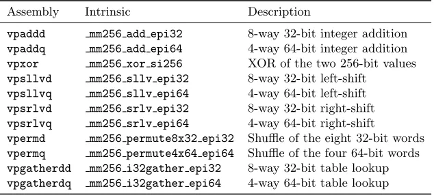
We focus on a small subset of the AVX2 instructions, with for each a brief explanation of what it does. For a better understanding, the most sophisticated instructions are also described with an equivalent description in C syntax using only general-purpose registers. Table 1 summarizes the main instructions along with their C intrinsic functions.
Table 1.Intrinsics of main AVX2 instructions useful to implement BLAKE.
Assembly Intrinsic Description
vpaddd mm256 add epi32 8-way 32-bit integer addition
vpaddq mm256 add epi64 4-way 64-bit integer addition
vpxor mm256 xor si256 XOR of the two 256-bit values
vpsllvd mm256 sllv epi32 8-way 32-bit left-shift
vpsllvq mm256 sllv epi64 4-way 64-bit left-shift
vpsrlvd mm256 srlv epi32 8-way 32-bit right-shift
vpsrlvq mm256 srlv epi64 4-way 64-bit right-shift
vpermd mm256 permute8x32 epi32 Shuffle of the eight 32-bit words
vpermq mm256 permute4x64 epi64 Shuffle of the four 64-bit words
vpgatherdd mm256 i32gather epi32 8-way 32-bit table lookup
vpgatherdq mm256 i32gather epi64 4-way 64-bit table lookup
Cross-lane permutes. AVX2 provides instructions to realize any permutation of 32- and 64-bit words within a YMM register, through the following instructions:vpermdshuffles 32-bit words of a full YMM register across lanes using two YMM registers as inputs: one as source, the other as the permutation’s indices:
u i n t 3 2 _ t a [8] , b [8] , c [ 8 ] ;
for ( i =0; i < 8; ++ i ) c [ i ] = a [ b [ i ]];
vpermqis similar tovpermdbut shuffles 64-bit words and takes an immediate operand instead as the permutation:
u i n t 6 4 _ t a [4] , c [ 4 ] ; int b ;
for ( i =0; i < 4; ++ i ) c [ i ] = a [( b > >(2* i ) ) % 4 ] ;
Vectorized table look-ups. The “gather” instructions are among the most remarkable of the AVX2 extensions:vpgatherddperforms eight table lookups in parallel, as in the code below:
u i n t 8 _ t * b ; u i n t 3 2 _ t scale , idx [8] , c [ 8 ] ;
for ( i =0; i < 8; ++ i ) c [ i ] = *( u i n t 3 2 _ t )( b + idx [ i ]* s c a l e );
vpgatherdqis quite similar to vpgatherdd, but works on four 64-bit words:
u i n t 8 _ t * b ; u i n t 3 2 _ t scale , idx [ 4 ] ; u i n t 6 4 _ t c [ 4 ] ;
for ( i =0; i < 4 ; + + i ) c [ i ] = *( u i n t 3 2 _ t )( b + idx [ i ]* s c a l e );
Insertion/extraction. AVX2 offers a number of instructions to manipulate words and YMM registers, of which the most relevant for us are the following.
Thevpinsrd instruction (already in AVX), also accessible by its intrinsic mm insert epi32, inserts one 32-bit word into a specified position in a XMM register, as follows:
u i n t 3 2 _ t c [8] , a ; int imm ; c [ imm ] = a ;
vpblendd (mm256 blend epi32), similar to the SSE4.1 pblendw instruction, permits the selec-tion of words from 2 different sources according to an immediate index, placing them in a third destination register:
u i n t 3 2 _ t a [8] , b [8] , c [ 8 ] ; int sel ; for ( i =0; i < 8; ++ i )
if (( sel > > i ) & 1 ) c [ i ] = b [ i ]; e l s e c [ i ] = a [ i ];
vextracti128 ( mm256 extracti128 si256) and vinserti128 ( mm256 inserti128 si256) ex-tract and insert an XMM register into the lower or upper halves of a YMM register.vextracti128
is equivalent to:
u i n t 3 2 _ t a [8] , c [ 4 ] ; int imm ;
for ( i =0; i < 4; ++ i ) c [ i ] = a [ i + 4* imm ];
whilevinserti128is equivalent to
3.3 AVX2 performance
Processors carrying the AVX2 instruction set are only expected to be available in 2013. There is currently no hard data on the performance of the instructions described above; one can, however, make some educated guesses, by using the Sandy Bridge as starting point.
The vpaddd, vpaddq, vpsllvd, vpsllvq, vpsrlvd, vpsrlvq, and vpxor instructions’ perfor-mance can be expected to be on-par with Sandy Bridge’svpxorinstruction, which requires a single cycle to complete. Thevpermdandvpermqinstructions cross register lanes; on Sandy Bridge, this adds one extra cycle of latency. We can estimate that this penalty gets no worse on Haswell, and thatvpermdandvpermqrequire two cycles to complete. The gather instructions remain the most elusive; it is unknown whether this consists of a large number of micro-ops, or uses dedicated circuitry. Assuming only one cache-line is accessed, one can expect at least four cycles of latency for the memory load, plus two for the extra logic.
We speculate that instruction parallelism in AVX2-compatible processors will resemble existing SSE2 parallelism available in current processors. Current Sandy Bridge processors are capable of executing three AVX instructions per cycle, namely one floating-point multiply, one floating-point add, and one logical operation. We expect future processors to be able to sustain such throughput with integer instructions, as it happens today with XMM registers.
3.4 XOP
In 2007, AMD announced its SSE5 set of new instructions. These featured 3-operand instruc-tions, more powerful permutainstruc-tions, native integer rotainstruc-tions, and fused-multiply-add capabilities. After the announcement of AVX, however, SSE5 was shelved in favor of AVX plus XOP, FMA4, and CVT16. The XOP instruction set [4] extends AVX with new integer multiply-and-accumulate (vpmac*), rotation (vprot*), shift (vpsha*,vpshl*), permutation (vpperm), and conditional move (vpcmov) instructions working on XMM registers. These instructions have latency at least two cy-cles. XOP instructions are integrated in AMD’s Bulldozer microarchitecture, which first appeared in the FX-series 32 nm processors released in on October 2011.
Below we present the most useful XOP instructions for BLAKE:
Rotate instructions. Whereas SSE and AVX requires rotations to be implemented with a combination of two shifts and an XOR, XOP introduces rotate instructions with either fixed or variable counts: the 3-operand vprotd (intrinsics mm roti epi32 and mm rot epi32) sets its destination XMM register to the four 32-bit words from a source register rotated by possibly different counts (positive for left rotation, negative for right);vprotq(intrinsics mm roti epi64
and mm rot epi64) is the equivalent instruction for 2-way 64-bit vectorized rotation.
Conditional move. The vpcmov instruction takes four operands among which a destination register has each of its bits set to the corresponding bit of either the first or the second source operand, depending on a selector third operand; this is similar to the “?” ternary operator in C.
vpcmov. accepts XMM or YMM registers as operands; for the latter, the instruction is equivalent to
u i n t 6 4 _ t a [4] , b [4] , c [4] , d [ 4 ] ;
for ( i =0; i < 4; ++ i ) d [ i ] = ( a [ i ] & c [ i ]) | ( b [ i ] & ~ c [ i ]);
4
Implementing BLAKE-512 with AVX2
This section first presents a basic SIMD implementation of BLAKE-512, using AVX2’s 4-way 64-bit SIMD instructions exactly in the same way that BLAKE-256 uses SSE2’s 4-way 32-bit instructions. We then discuss optimizations exploiting instructions proper to AVX2. For ease of understanding, we present C code using intrinsics for AVX2 instructions; excerpts of our assembly implementation can be found in Appendix B.1, and the full assembly will be publicly available.
We used Intel’s Software Development Emulator3 to test the correctness of the AVX2 im-plementations, and the latest trunk build of the Yasm assembler4 (as the latest release did not support AVX2) to compile them.
4.1 Basic SIMD C implementation
AVX2 provides instructions to write a straightforward SIMD implementation of BLAKE-512 simi-lar to thesse2implementation of BLAKE-256 in Appendix A, except that 256-bit YMM registers are used to hold four 64-bit words instead of 128-bit XMM registers being used to hold four 32-bit words.
The code below implements the column step of BLAKE-512’s round function, that is, it com-putes the first four instance ofGin parallel. The 4×4 state of 64-bit words is stored in four YMM registers defined as m256i type and aliasedrow1,row2,row3, androw4.
b u f 1 = _ m m 2 5 6 _ s e t _ e p i 6 4 x ( m [ sig [ r ][6]] , m [ sig [ r ][4]] , m [ sig [ r ][2]] , m [ sig [ r ] [ 0 ] ] ) ; b u f 2 = _ m m 2 5 6 _ s e t _ e p i 6 4 x ( u [ sig [ r ][7]] , u [ sig [ r ][5]] ,
u [ sig [ r ][3]] , u [ sig [ r ] [ 1 ] ] ) ; b u f 1 = _ m m 2 5 6 _ x o r _ s i 2 5 6 ( buf1 , b u f 2 );
r o w 1 = _ m m 2 5 6 _ a d d _ e p i 6 4 ( _ m m 2 5 6 _ a d d _ e p i 6 4 ( row1 , b u f 1 ) , r o w 2 ); r o w 4 = _ m m 2 5 6 _ x o r _ s i 2 5 6 ( row4 , r o w 1 );
r o w 4 = _ m m 2 5 6 _ x o r _ s i 2 5 6 ( _ m m 2 5 6 _ s r l i _ e p i 6 4 ( row4 , 32) , _ m m 2 5 6 _ s l l i _ e p i 6 4 ( row4 , 3 2 ) ) ; r o w 3 = _ m m 2 5 6 _ a d d _ e p i 6 4 ( row3 , r o w 4 );
r o w 2 = _ m m 2 5 6 _ x o r _ s i 2 5 6 ( row2 , r o w 3 );
b u f 1 = _ m m 2 5 6 _ s e t _ e p i 6 4 x ( u [ sig [ r ][6]] , u [ sig [ r ][4]] , u [ sig [ r ][2]] , u [ sig [ r ] [ 0 ] ] ) ; b u f 2 = _ m m 2 5 6 _ s e t _ e p i 6 4 x ( m [ sig [ r ][7]] , m [ sig [ r ][5]] ,
m [ sig [ r ][3]] , m [ sig [ r ] [ 1 ] ] ) ; b u f 1 = _ m m 2 5 6 _ x o r _ s i 2 5 6 ( buf1 , b u f 2 );
r o w 2 = _ m m 2 5 6 _ x o r _ s i 2 5 6 ( _ m m 2 5 6 _ s r l i _ e p i 6 4 ( row2 , 25) , _ m m 2 5 6 _ s l l i _ e p i 6 4 ( row2 , 3 9 ) ) ;
r o w 1 = _ m m 2 5 6 _ a d d _ e p i 6 4 ( _ m m 2 5 6 _ a d d _ e p i 6 4 ( row1 , b u f 1 ) , r o w 2 ); r o w 4 = _ m m 2 5 6 _ x o r _ s i 2 5 6 ( row4 , r o w 1 );
r o w 4 = _ m m 2 5 6 _ x o r _ s i 2 5 6 ( _ m m 2 5 6 _ s r l i _ e p i 6 4 ( row4 , 16) , _ m m 2 5 6 _ s l l i _ e p i 6 4 ( row4 , 4 8 ) ) ; r o w 3 = _ m m 2 5 6 _ a d d _ e p i 6 4 ( row3 , r o w 4 );
r o w 2 = _ m m 2 5 6 _ x o r _ s i 2 5 6 ( row2 , r o w 3 );
r o w 2 = _ m m 2 5 6 _ x o r _ s i 2 5 6 ( _ m m 2 5 6 _ s r l i _ e p i 6 4 ( row2 , 11) , _ m m 2 5 6 _ s l l i _ e p i 6 4 ( row2 , 5 3 ) ) ;
r o w 2 = _ m m 2 5 6 _ p e r m u t e 4 x 6 4 _ e p i 6 4 ( row2 , _ M M _ S H U F F L E (0 ,3 ,2 ,1)); r o w 3 = _ m m 2 5 6 _ p e r m u t e 4 x 6 4 _ e p i 6 4 ( row3 , _ M M _ S H U F F L E (1 ,0 ,3 ,2)); r o w 4 = _ m m 2 5 6 _ p e r m u t e 4 x 6 4 _ e p i 6 4 ( row4 , _ M M _ S H U F F L E (2 ,1 ,0 ,3));
A simple optimization consists in implementing the rotation by 32 bits using thevpshufd instruc-tion, which implements “in-lane” shuffle of 32-bit words. That is, the line
3
http://software.intel.com/en-us/articles/intel-software-development-emulator/
4
r o w 4 = _ m m 2 5 6 _ x o r _ s i 2 5 6 ( _ m m 2 5 6 _ s r l i _ e p i 6 4 ( row4 , 32) , _ m m 2 5 6 _ s l l i _ e p i 6 4 ( row4 , 3 2 ) ) ;
can be replaced by
r o w 4 = _ m m 2 5 6 _ s h u f f l e _ e p i 3 2 ( row4 , _ M M _ S H U F F L E (2 ,3 ,0 ,1));
Similarly, the rotations by 16 bits can be implemented using vpshufbin a similar fashion as the
ssse3implementation (see Appendix A.3):
r o w 4 = _ m m 2 5 6 _ s h u f f l e _ e p i 8 ( row4 , r16 );
where r16is the alias of a YMM register containing the index values for the byte ofrow4 at its respective lane and position.
Based on the estimates in §§3.3, we expect to save at least one cycle per rotation of 16 or 32 bits, thus four cycles per round, 64 cycles per compression function, that is, at least 0.5 cycle per byte.
4.2 Parallelized message loading
As observed in§§3.2, thevpgatherdqinstruction can be used to load words from arbitrary memory addresses. To load message words according to the σr permutation, one would thus write the
following C code:
_ m 2 5 6 i m0 = _ m m _ i 3 2 g a t h e r _ e p i 6 4 ( m , s i g m a [ r ][0] , 8); _ m 2 5 6 i m1 = _ m m _ i 3 2 g a t h e r _ e p i 6 4 ( m , s i g m a [ r ][1] , 8); _ m 2 5 6 i m2 = _ m m _ i 3 2 g a t h e r _ e p i 6 4 ( m , s i g m a [ r ][2] , 8); _ m 2 5 6 i m3 = _ m m _ i 3 2 g a t h e r _ e p i 6 4 ( m , s i g m a [ r ][3] , 8);
wheresigma[r][i]’s are m128itype, and where each 32-bit word holds an index of the permu-tation. As eachsigma[r][i]holds four indices,sigma[r][0]tosigma[r][3]hold the 16 indices of theσr permutation.
Such a sequential implementation of fourvpgatherdq’s is expected to only add an extra latency equivalent to that of a single vpgatherdq, since the subsequent instructions (XOR, etc.) only depend on the first call, and therefore may not stall while the three others loads are executed. This assumes, of course, thatvpgatherdqis pipelined, and the subsequent loads can start 1 cycle after the first one.
4.3 Message caching
As discussed in the previous section, loading the message words according to theσpermutations takes a considerable number of cycles, compared to an arithmetic operation. A potential optimiza-tion consists in eliminating redundancies due to the reuse of six of the tenσpermutations, in the first and last six rounds. That is, a same permuted message is used twice for the permutations σ0, σ1, . . . , σ5. An implementation strategy could thus be:
1. in rounds 0 to 5: compute the permuted messages, and store the result in memory (preferably in unused YMM registers)
2. in rounds 6 to 9: compute the permuted messages without storing the result
3. in rounds 10 to 15: do not compute the permuted messages, but rather use the registers set in step 1
To save six vectorized XOR’s, one should store the permuted message already XORed with the constants, as the latter are reused as well.
4.4 Performance estimates
Based on estimations in §§3.3, one can attempt to predict the speed of an implementation of BLAKE-512 with AVX2. For simplicity, we assume that no message caching is used (as we’ll see later, this seems to be a reasonable assumption). An attempt of a rough performance estimate may consider the following assumptions:
• Message loading takes 5 cycles per step (latency of onevpgatherdq). • Each addition or XOR consumes one cycle, and all are computed serially.
• XORs between message and constants are computed in parallel to other operations (message loads or shuffles), and thus are not counted.
• Rotations by 32 or 16 bits take one cycle, while those by 25 or 11 bits take three cycles. • Of the three shuffles performed for (un)diagonalization, two are computed in parallel to
addi-tions or XORs.
• Initialization and finalization of the compression function add an overhead of respectively 10 and 6 cycles.
This estimates each round to 2×(5 + 10 + 2 + 6 + 2) = 52 cycles, thus 52×16 + 16 = 848 cycles for the compression function, that is, 6.63 cycles per byte of message. We stress that that only benchmarks on real hardware would provide reliable speed figures. We only make that estimate as an attempt to predict the real speed based on the data available and on our experiments with AVX.
The lower bound, of course, is much lower: if one simply considers the cost of theGi functions,
the speed of BLAKE-512 on AVX2 can become as low as (16×2×(4 + (3 + 3 + 1 + 1) + 4))/128, or 4.00 cycles per byte.
5
Implementing BLAKE-256 with AVX2
This section shows how BLAKE-256 can benefit of AVX2. Unlike BLAKE-512, BLAKE-256 is not naturally adaptable to 256-bit vectors, as there is a maximum of four Gi independently-running
functions per round. Nevertheless, it is possible to take advantage of AVX2 to speedup BLAKE-256 (although the trick of message caching applies, we discuss it in §6, as it is not proper to AVX2). Excerpts of our assembly implementation appear in Appendix B.2.
5.1 Optimizing message loads
The first way to improve message loads is by using the vpgatherdd instruction from the AVX2 instruction set. To perform the full 16-word message permutation required in each round, only four operations are required:
_ m 1 2 8 i m0 = _ m m _ i 3 2 g a t h e r _ e p i 3 2 ( m , s i g m a [ r ][0] , 4); _ m 1 2 8 i m1 = _ m m _ i 3 2 g a t h e r _ e p i 3 2 ( m , s i g m a [ r ][1] , 4); _ m 1 2 8 i m2 = _ m m _ i 3 2 g a t h e r _ e p i 3 2 ( m , s i g m a [ r ][2] , 4); _ m 1 2 8 i m3 = _ m m _ i 3 2 g a t h e r _ e p i 3 2 ( m , s i g m a [ r ][3] , 4);
This can be further improved by using only two YMM registers to store the permuted message:
_ m 2 5 6 i m01 = _ m m 2 5 6 _ i 3 2 g a t h e r _ e p i 3 2 ( m , s i g m a [ r ][0] , 4); _ m 2 5 6 i m23 = _ m m 2 5 6 _ i 3 2 g a t h e r _ e p i 3 2 ( m , s i g m a [ r ][1] , 4);
The individual 128-bit blocks of message are then accessible through thevextracti128instruction. One must also consider the possibility thatvpgatherddwill not have acceptable performance, perhaps due to specific processor design idiosyncrasies; AVX2 can still help us, via the vpermd
t m p 0 = _ m m 2 5 6 _ p e r m u t e v a r 8 x 3 2 _ e p i 3 2 ( m01 , s i g m a 0 0 ); t m p 1 = _ m m 2 5 6 _ p e r m u t e v a r 8 x 3 2 _ e p i 3 2 ( m23 , s i g m a 0 1 ); t m p 2 = _ m m 2 5 6 _ p e r m u t e v a r 8 x 3 2 _ e p i 3 2 ( m01 , s i g m a 1 0 ); t m p 3 = _ m m 2 5 6 _ p e r m u t e v a r 8 x 3 2 _ e p i 3 2 ( m23 , s i g m a 1 1 ); m01 = _ m m 2 5 6 _ b l e n d _ e p i 3 2 ( tmp0 , tmp1 , m a s k 0 ); m23 = _ m m 2 5 6 _ b l e n d _ e p i 3 2 ( tmp2 , tmp3 , m a s k 1 );
In the above code, we permute the elements from the first YMM register into their proper order in the permutation, after which we permute the elements from the second. A simple blend instruction suffices to obtain the correct permutation. We repeat the process for the second part of the permutation. Once again, individual 128-bit blocks are available viavextracti128.
5.2 Tree hashing
Observe that AVX2 allows to use the 256-bit width of YMM registers to compute two keyed per-mutations in parallel, that is, where each 128-bit lane of YMM registers processes an independent block: the instructionvpadddcan perform the two 4-way additions in parallel, a singlevpermdcan rotate two rows in the (un)diagonalization step, etc. Overall, it is easy to see that compressing two blocks with this technique will be close to twice as fast as two single-stream compressions.
This technique may be exploited to implement a tree hashing mode, wherein two independent nodes or leaves are processed in parallel. In particular, a binary tree hashing mode processing a 2n−1-block message could be implemented with 2n−1 double-compressions rather than 2n−1
compressions (if leaves are as large as a message block).
If the classical (non-tree) mode is used, BLAKE can also benefit of this technique to hash two messages simultaneously. Note that the indices of the message blocks need not be synchronized, as different counter values may be used for each of the two blocks processed in parallel.
When combined with multi-core and multithreading technologies (as implemented in new pro-cessors), we expect this technique to allow extremely high speed for both tree hashing and multi-stream processing.
6
Implementing BLAKE with AVX
We report on our efforts to optimize BLAKE-256 and BLAKE-512 for AVX, using 3-operand instructions, manual rescheduling, and a number of minor tricks. Our assemblyavxs (BLAKE-256) andavx(BLAKE-512) implementations are available in SUPERCOP.
6.1 Message caching
Like BLAKE-512, BLAKE-256 reuses several permuted messages, namely four. Due to the smaller number of redundant permuted messages and the smaller messages, this full state (4×4×128 bits) can be stored in eight YMM registers. This leaves the possibility of either storing all entries, or to keep some in registers. Permuted messages are easily stored using thevinserti128instruction:
// F i r s t 4 p e r m u t e d e l e m e n t s
c a c h e _ r e g = _ m m 2 5 6 _ i n s e r t i 1 2 8 _ s i 2 5 6 ( c a c h e _ r e g , buf1 , 0); ...
// S e c o n d 4 p e r m u t e d e l e m e n t s
c a c h e _ r e g = _ m m 2 5 6 _ i n s e r t i 1 2 8 _ s i 2 5 6 ( c a c h e _ r e g , buf1 , 1); _ m m 2 5 6 _ s t o r e _ s i 2 5 6 (& c a c h e [ r ] , c a c h e _ r e g );
In rounds 10 and above, we can retrieve the cached permutations with a simple load and extract:
c a c h e _ r e g = _ m m 2 5 6 _ l o a d _ s i 2 5 6 (& c a c h e [ r ]); b u f 1 = _ m m _ e x t r a c t i 1 2 8 ( c a c h e _ r e g , 0); ...
b u f 1 = _ m m _ e x t r a c t i 1 2 8 ( c a c h e _ r e g , 1);
6.2 Results
We ran benchmarks on an Intel Core i7 2630QM (2 GHz, Sandy Bridge), reusing tools from SU-PERCOP [6] for measuring speed on long messages, and compiling our code with Intel’sicc com-piler, with options-fast -xHost -funroll-loops -unroll-aggressive -inline-forceinline -no-inline-max-total-size (that is, maximal code inlining and loop unrolling). BLAKE-256 was measured at 7.47 cycles per byte, and BLAKE-512 at 5.71 cycles per byte. Surprisingly, message caching did not improve, nor degrade, performance.
7
Implementing BLAKE with XOP
This section shows the main XOP-specific optimizations for BLAKE-256 and BLAKE-512, with a focus on the former. Although only a limited number of XOP instructions can be exploited, they provide a significant speed-up compared to implementations using AVX but not XOP. The latest version of ourxopimplementations can be found in SUPERCOP.
7.1 Faster rotations
The first optimization is straightforward, as it just consists in doing rotations with the dedicated
vprot*instruction. In BLAKE-256, rotations by 16 and 8, previously implemented with SSSE3’s
pshufb, can also be replaced withvprotd. The first half ofGcan thus be coded as
r o w 1 = _ m m _ a d d _ e p i 3 2 ( _ m m _ a d d _ e p i 3 2 ( row1 , buf ) , r o w 2 ); r o w 4 = _ m m _ x o r _ s i 1 2 8 ( row4 , r o w 1 );
r o w 4 = _ m m _ r o t i _ e p i 3 2 ( row4 , -16); r o w 3 = _ m m _ a d d _ e p i 3 2 ( row3 , r o w 4 ); r o w 2 = _ m m _ x o r _ s i 1 2 8 ( row2 , r o w 3 ); r o w 2 = _ m m _ r o t i _ e p i 3 2 ( row2 , -12);
Similarly,vprotq can be used in BLAKE-512.
For BLAKE-256, we save two instructions per 12 or 7 rotation, thus 8 instructions per round, and 112 per compression. In the Bulldozer microarchitecture, shifts (vpslldandvpslrd) have a latency of 3 cycles, and vpxorof 2: a rotation thus takes 6 cycles, as the shifts can be pipelined within the execution unit (assuming a new instruction can start at every cycle). Sincevprotdhas latency 2, we can expect to save 4 cycles per rotation, thus 4×4×14 = 224 cycles per compression, that is, 3.5 cycles per byte. This figure may be slightly lower in practice, due to the pipelining of other instructions during the execution of the shift-shift-xor.
For BLAKE-512, we save four instructions per 25 or 11 rotation, thus 16 instructions per round, and 256 per compression. Now on Bulldozer, we can expect the rotations (withoutvprotq) to complete in 8 cycles, due to the pipelining of the four 3-cycle latency shifts. Assuming the two vprotq’s are pipelined as well to complete in 3 cycles, we save 5 cycles per rotation, thus 5×4×16 = 320 per compression, that is, 2.5 cycles per byte. Again, the context may slightly lower this estimate in practice.
7.2 Optimizing message loads
XOP can be used to implement BLAKE’s message permutation without memory look-ups, that is, by reorganizing the ordered wordsm0, . . . , m15within registers, similarly to the approach in§§5.1. The key operation is vpperm’s conditional moves, that allow us to copy up to four arbitrary message words out of eight into an XMM register. For example in the first column step of the first round, an XMM register needs be loaded withm0, m2, m4, m6; with XMM registersm0and
m1respectively holdingm0 tom3 andm4 tom7, this can be done as
A complete definition of thevppermselector can be found in [4, p235]. Note that, unlike message words, constant words can be loaded directly, to be XORed with the message:
s1 = _ m m _ s e t _ e p i 3 2 (0 x e c 4 e 6 c 8 9 ,0 x 2 9 9 f 3 1 d 0 ,0 x 3 7 0 7 3 4 4 ,0 x 8 5 a 3 0 8 d 3 ); buf = _ m m _ x o r _ s i 1 2 8 ( s0 , s1 );
A same procedure can be followed when the four message words to be loaded span three or four message registers—where the i-th register, i = 0,1,2,3, holds m4i to m4i+1. An example of the latter case occurs in the first message load of the fourth round, where we need the following code:
s0 = _ m m _ p e r m _ e p i 8 ( m0 , m1 , _ m m _ s e t _ e p i 3 2 ( SEL (0) , SEL (0) , SEL (3) , SEL ( 7 ) ) ); s0 = _ m m _ p e r m _ e p i 8 ( s0 , m2 , _ m m _ s e t _ e p i 3 2 ( SEL (7) , SEL (2) , SEL (1) , SEL ( 0 ) ) ); s0 = _ m m _ p e r m _ e p i 8 ( s0 , m3 , _ m m _ s e t _ e p i 3 2 ( SEL (3) , SEL (5) , SEL (1) , SEL ( 0 ) ) ); s1 = _ m m _ s e t _ e p i 3 2 (0 x 3 f 8 4 d 5 b 5 ,0 x c 0 a c 2 9 b 7 ,0 x 8 5 a 3 0 8 d 3 ,0 x 3 8 d 0 1 3 7 7 );
buf = _ m m _ x o r _ s i 1 2 8 ( s0 , s1 );
whereSELis a macro that forms the appropriate selector.
Each round requires four message loads (two in each step). Of the ten permutations,
1. 6 use 2 message registers (thus onevpperm) 2. 30 use 3 message registers (thus twovpperm’s) 3. 4 use 4 message registers (thus three vpperm’s)
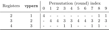
In total, 78 calls tovppermare necessary to implement the first 10 permutations (e.g. when message caching is used), and 94 if the first rounds’ loads are recomputed (see Table 2 for the detailed distribution). These numbers may be reduced with new implementation techniques eliminating redundancies, for example by reusing previously loaded messages to avoid 3-vppermloads.
Note that one could use vpinsrdinstead of vppermfor single-word insertions. This does not improve speed, however, asvpinsrdhas a latency of 12 cycles on Bulldozer, as opposed to simply 2 for thevpperm, due to the decoupling of integer and floating-point units.
Table 2.Number of message loads requiring either one, two, or three calls tovpperm, as a function of the permutation.
Registers vpperm Permutation (round) index
0 1 2 3 4 5 6 7 8 9
2 1 4 - - - 1 1
3 2 - 4 4 3 3 4 4 3 2 3
4 3 - - - 1 1 - - 1 1
-A similar approach can be used to implement BL-AKE-512 message loads, however it requires about twice as many calls tovpperm, as this does not support 256-bit YMM registers.
7.3 Results
We present benchmarks of our C XOP implementation on our FX-8150 processor clocked at 3.6 GHz, after disabling automatic overclocking (AMD’s Turbo Core 2.0 technology) in the BIOS, which proved more reliable than doing it temporarily in the OS (Ubuntu 11.10). Measurements were realized for long messages with the same methodology as SUPERCOP. The compiler used is
gcc 4.6.1.
BLAKE-256. On long messages, our xopimplementation runs at 11.64 cycles per byte, against 15.06 for the fastest non-XOP implementation, namely the icc-compiledavxicc. The code was compiled with options-mxop -fomit-frame-pointer -O -march=bdver1 -funroll-loops.
Note that a simple lower bound on the cycle-per-byte figure can be given for the Bulldozer architecture: with 12 flow-dependent vector operations5 in a 4×Ghaving latency at least 2, and with 2×14 steps, we obtain 12×2×2×14/64 = 10.50 cycles per byte.
BLAKE-512. On long messages, our xopimplementation runs at 6.95 cycles per byte, against 9.09 for the fastest non-XOP implementation (our AVX code). The code was compiled with options
-mxop -fomit-frame-pointer -O3 -funroll-loops.
As with BLAKE-256, one can attempt to lower bound the speed of BLAKE-512 on Bulldozer. A straightforward bound assuming parallelism of each two 2-way vector operations is likely to be too loose, as some operations share a single execution unit (namely, this approach gives a bound of 6 cycles per byte). Assuming 1 cycle of penalty due to the rotations being bound to a single execution unit, this leaves us at 13 cycles perGi, or 6.5 cycles per byte.
8
Conclusion
We first considered the future AVX2 256-bit vector extensions, and identified the most useful instructions to implement add-rotate-xor algorithms, and BLAKE in particular. We wrote assem-bly implementations of BLAKE-256 and BLAKE-512 exploiting AVX2’s unique features, such as SIMD memory look-up. Although we could test the correctness of our implementations using Intel’s emulator, actual benchmarks will have to wait until 2013 for processors implementing the Haswell microarchitecture. We observed that AVX2 may boost the performance of BLAKE-256 in tree and multistream mode, thanks to its ability to compute two instances with a single vector state.
We then reviewed the applicability of the recent AVX and XOP advanced vector instructions, as respectively found in Intel and AMD latest CPUs, to implementations of BLAKE-256. While AVX provides a minor speed-up compared to SSE4 implementations, the powerful XOP instructions lead to a considerable improvement of more than 3 and 2 cycles per byte for 256 and BLAKE-512, respectively. This is in mainly due to the dedicated rotation instructions, and to thevpperm
instruction, which allows permuted message blocks to be reconstructed very efficiently. Although message loads take up a considerable amount of instructions, our proposed technique of message caching doesn’t seem to improve (neither degrade) speed, be it on Intel’s or AMD’s hardware.
Acknowledgments
We thank NAGRA (Kudelski Group) for supporting the purchase of a computer equiped with a Bulldozer processor.
References
1. Aumasson, J.P., Henzen, L., Meier, W., Phan, R.C.W.: SHA-3 proposal BLAKE. Submission to the SHA-3 competition (2008)http://www.131002.net/blake/.
2. Intel: Advanced vector extensions programming reference. http://software.intel.com/en-us/avx/
(March 2008) Document no. 319433-002.
3. Intel: Advanced vector extensions programming reference. http://software.intel.com/en-us/avx/
(June 2011) Document no. 319433-012a.
4. AMD: AMD64 Architecture Programmers Manual Volume 6: 128-Bit and 256-Bit XOP, FMA4 and CVT16 Instructions. http://developer.amd.com/documentation/guides/Pages/default.aspx# manuals(November 2009)
5
5. Gueron, S., Krasnov, V.: Parallelizing message schedules to accelerate the computations of hash func-tions. Cryptology ePrint Archive, Report 2012/067 (2012)http://eprint.iacr.org/.
6. Bernstein, D.J., Lange, T.: eBACS: ECRYPT Benchmarking of Cryptographic Systems. http:// bench.cr.yp.to/Accessed May 16, 2012.
7. Intel: C++ Intrinsics Reference (2007) Document no. 312482-002US.
8. Coke, J., Baliga, H., Cooray, N., Gamsaragan, E., Smith, P., Yoon, K., Abel, J., Valles, A.: Im-provements in the Intel Core 2 Penryn Processor Family Architecture and Microarchitecture. Intel Technology Journal12(3) (October 2008) 179–193
A
Previous SIMD implementations of BLAKE
A number of previous implementations of BLAKE (as included SUPERCOP [6]) have used Intel’s Streaming SIMD Extensions (SSE) instruction sets to exploit the parallelism of BLAKE for im-proved performance. This section gives a brief overview of those implementations, starting with a presentation of the SSE2 instruction set.
A.1 Streaming SIMD Extensions 2 (SSE2)
Intel’s first set of instructions supporting all 4-way 32-bit SIMD operations necessary to implement BLAKE-256 is the Streaming SIMD Extensions 2 (SSE2) set. SSE2 includes vector instructions on 4×32-bit words for integer addition, XOR, word-wise left and right shift, as well as word shuffle. This is all one needs to implement BLAKE-256’s round function, as rotations can be simulated by two shifts and an XOR. 512 can also use SSE2 (though with less benefit than BLAKE-256), thanks to the support of 2-way 64-bit SIMD operations.
SSE2 instructions operate on 128-bit XMM registers, rather than 32 or 64-bit general-purpose registers. In 64-bit mode (x86-64 a/k/a amd64 architecture) 16 XMM registers are available, whereas only eight are available in 32-bit mode. The SSE2 instructions are supported by all recent Intel and AMD desktop and laptop processors (Intel’s Xeon, Celeron, Core X’s, etc.; AMD’s Athlon 64, Opteron, etc.) as well as by common low-voltage processors, as found in netbooks (Intel’s Atom; VIA’s C7 and Nano).
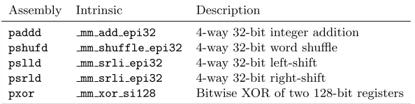
In addition to inline assembly, C(++) programmers can use SSE2 instructions via intrinsic functions(or intrinsics), which are API extensions built into the compiler. Intrinsics allow to en-force the use of SSE2 instructions by the processor, enable the use of C syntax and variables instead of assembly language and hardware registers, and let the compiler optimize instruction scheduling for better performance. Table 3 shows intrinsics corresponding to some assembly mnemonics used to implement BLAKE-256. A complete reference to SSE2 intrinsics can be found in [7].
Table 3. Intrinsics of main SSE2 instructions used to implement BLAKE-256.
Assembly Intrinsic Description
paddd mm add epi32 4-way 32-bit integer addition
pshufd mm shuffle epi32 4-way 32-bit word shuffle
pslld mm srli epi32 4-way 32-bit left-shift
psrld mm srli epi32 4-way 32-bit right-shift
pxor mm xor si128 Bitwise XOR of two 128-bit registers
A.2 SIMD implementation of BLAKE-256 using SSE2
row1,row2,row3, androw4. These respectively correspond to the first four rows of the 4×4 array representation described in§2.
First, one initializes a 128-bit XMM register aliasedbuf1with the four message wordsmσr[2i]. Another XMM register aliasedbuf2is initialized with the four constantsuσr[2i+1].buf1andbuf2 are XORed together intobuf1and the result is added torow1:
b u f 1 = _ m m _ s e t _ e p i 3 2 ( m [ sig [ r ][6]] , m [ sig [ r ][4]] , m [ sig [ r ][2]] , m [ sig [ r ] [ 0 ] ] ) ; b u f 2 = _ m m _ s e t _ e p i 3 2 ( u [ sig [ r ][7]] , u [ sig [ r ][5]] ,
u [ sig [ r ][3]] , u [ sig [ r ] [ 1 ] ] ) ; b u f 1 = _ m m _ x o r _ s i 1 2 8 ( buf1 , b u f 2 );
r o w 1 = _ m m _ a d d _ e p i 3 2 ( row1 , b u f 1 );
At this state, one can already prepare the XMM register containing the XOR of the permuted message and constants for the next message input:
b u f 1 = _ m m _ s e t _ e p i 3 2 ( m [ sig [ r ][7]] , m [ sig [ r ][5]] , m [ sig [ r ][3]] , m [ sig [ r ] [ 1 ] ] ) ; b u f 2 = _ m m _ s e t _ e p i 3 2 ( u [ sig [ r ][6]] , u [ sig [ r ][4]] ,
u [ sig [ r ][2]] , u [ sig [ r ] [ 0 ] ] ) ; b u f 1 = _ m m _ x o r _ s i 1 2 8 ( buf1 , b u f 2 );
The subsequent operations are only vectorized XOR, integer addition, and word-wise shifts:
r o w 1 = _ m m _ a d d _ e p i 3 2 ( row1 , r o w 2 ); r o w 4 = _ m m _ x o r _ s i 1 2 8 ( row4 , r o w 1 );
r o w 4 = _ m m _ x o r _ s i 1 2 8 ( _ m m _ s r l i _ e p i 3 2 ( row4 , 16 ) , _ m m _ s l l i _ e p i 3 2 ( row4 , 16 )); r o w 3 = _ m m _ a d d _ e p i 3 2 ( row3 , r o w 4 );
r o w 2 = _ m m _ x o r _ s i 1 2 8 ( row2 , r o w 3 );
r o w 2 = _ m m _ x o r _ s i 1 2 8 ( _ m m _ s r l i _ e p i 3 2 ( row2 , 12 ) , _ m m _ s l l i _ e p i 3 2 ( row2 , 20 )); r o w 1 = _ m m _ a d d _ e p i 3 2 ( row1 , b u f 1 );
r o w 1 = _ m m _ a d d _ e p i 3 2 ( row1 , r o w 2 ); r o w 4 = _ m m _ x o r _ s i 1 2 8 ( row4 , r o w 1 );
r o w 4 = _ m m _ x o r _ s i 1 2 8 ( _ m m _ s r l i _ e p i 3 2 ( row4 , 8 ) , _ m m _ s l l i _ e p i 3 2 ( row4 , 24 )); r o w 3 = _ m m _ a d d _ e p i 3 2 ( row3 , r o w 4 );
r o w 2 = _ m m _ x o r _ s i 1 2 8 ( row2 , r o w 3 );
r o w 2 = _ m m _ x o r _ s i 1 2 8 ( _ m m _ s r l i _ e p i 3 2 ( row2 , 7 ) , _ m m _ s l l i _ e p i 3 2 ( row2 , 25 ));
At the end of a column step, each register is word-rotated to perform the diagonal step as a column step on the rotated state, as observed in§2:
r o w 2 = _ m m _ s h u f f l e _ e p i 3 2 ( row2 , _ M M _ S H U F F L E (0 ,3 ,2 ,1) ); r o w 3 = _ m m _ s h u f f l e _ e p i 3 2 ( row3 , _ M M _ S H U F F L E (1 ,0 ,3 ,2) ); r o w 4 = _ m m _ s h u f f l e _ e p i 3 2 ( row4 , _ M M _ S H U F F L E (2 ,1 ,0 ,3) );
The mm shuffle epi32intrinsic takes as second argument an immediate value (a constant integer literal) expressed as a predefined macro. We refer to [7, p.65] for details of the MM SHUFFLEmacro.
A.3 Implementations using SSSE3 and SSE4.1
The SSE2 instruction set was followed by the SSE3, SSSE3, SSE4.1 and SSE4.2 extensions [7], which brought additional instructions to operate on XMM registers. It was found that some of those instructions could be of benefit to BLAKE, and implementations exploiting SSSE3 and SSE4.1 instructions have been submitted to SUPERCOP:
little-endian to big-endian byte order, since both can be expressed as byte shuffles (in the
sse2 implementations rotations were implemented as two shifts and an XOR). This brings a significant speed-up on Core 2 based on the Penryn microarchitecture, which introduced a dedicated shuffle unit to completepshufbwithin one micro-operation, against four on the first Core 2 chips [8].
• The sse41 implementation of BLAKE-256 uses the pblendw instruction (mm blend epi16) in combination with SSE2’s pshufd,pslldq, and others to load manduwords according to theσpermutations without using table lookups.
In general, the ssse3 implementation is faster than sse2, and sse41 is faster than both6. For example, the 20110708 measurements of SUPERCOP on sandy0 (a machine equipped with a Sandy Bridge Core i7, without AVX activated) report sse41 as the fastest implementation of BLAKE-256, with thessse3andsse2 implementations being respectively 4 % and 24 % slower.
Recently, SUPERCOP included thevect128andvect128-mmxhackimplementations of BLAKE-256 by Leurent, which slightly outperform the sse41 implementation. The main singularity of Leurent’s code is its implementation of theσ permutations:vect128 “byte-slices” each message word accross four XMM registers and uses the pshufb instruction to reorder them according to σ; vect128-mmxhack instead uses MMX and general-purpose registers to store and unpack the message words in the correct order into XMM registers.
B
AVX2 assembly implementations (excerpts)
This section presents excerpts from our assembly implementations. The full implementations will be made publicly available.
B.1 BLAKE-512 assembly for AVX2
Implementation ofG, with permuted message in%3and%4:
; H e l p e r w o r d r o t a t i o n m a c r o % m a c r o V P R O T R Q 2
v p s l l q ymm8 , %1 , 64 -%2 ; x < < 32 - c v p s r l q %1 , %1 , %2 ; x > > c
v p x o r %1 , %1 , y m m 8 % e n d m a c r o
; ymm0 -3: S t a t e
; ymm4 -7: m_ {\ s i g m a } xor c_ {\ s i g m a } ; ymm8 -9: F r e e t e m p r e g i s t e r s
; ymm10 - 1 3 : m % m a c r o G 2
v p a d d q ymm0 , ymm0 , %1 ; r o w 1 + b u f 1 v p a d d q ymm0 , ymm0 , y m m 1 ; r o w1 + r o w 2 v p x o r ymm3 , ymm3 , y m m 0 ; r o w4 ^ r o w 1 v p s h u f d ymm3 , ymm3 , 1 0 1 1 0 0 0 1 b ; r ow 4 > > > 32
v p a d d q ymm2 , ymm2 , y m m 3 ; r ow 3 + r o w 4 v p x o r ymm1 , ymm1 , y m m 2 ; r ow 2 ^ r o w 3 V P R O T R Q ymm1 , 25 ; r o w 2 > > > 25
v p a d d q ymm0 , ymm0 , %2 ; r o w 1 + b u f 1 v p a d d q ymm0 , ymm0 , y m m 1 ; r o w 1 + r o w 2 v p x o r ymm3 , ymm3 , y m m 0 ; r o w 4 ^ r o w 1 v p s h u f b ymm3 , ymm3 , y m m 1 5 ; r o w 4 > > > 16
6
v p a d d q ymm2 , ymm2 , y m m 3 ; r ow 3 + r o w 4 v p x o r ymm1 , ymm1 , y m m 2 ; r ow 2 + r o w 3 V P R O T R Q ymm1 , 11 ; ro w 2 > > > 11 % e n d m a c r o
Message loading:
% m a c r o M S G L O A D 1
v p c m p e q q ymm14 , ymm14 , y m m 1 4 ; F F . . F F v m o v d q a xmm8 , [ p e r m + % 1 * 6 4 + 00] v p g a t h e r d q ymm4 , [ rsp + 8* x m m 8 ] , y m m 1 4
v p c m p e q q ymm14 , ymm14 , y m m 1 4 ; F F . . F F v m o v d q a xmm9 , [ p e r m + % 1 * 6 4 + 16] v p g a t h e r d q ymm5 , [ rsp + 8* x m m 9 ] , y m m 1 4
v p c m p e q q ymm14 , ymm14 , y m m 1 4 ; F F . . F F v m o v d q a xmm8 , [ p e r m + % 1 * 6 4 + 32] v p g a t h e r d q ymm6 , [ rsp + 8* x m m 8 ] , y m m 1 4
v p c m p e q q ymm14 , ymm14 , y m m 1 4 ; F F . . F F v m o v d q a xmm9 , [ p e r m + % 1 * 6 4 + 48] v p g a t h e r d q ymm7 , [ rsp + 8* x m m 9 ] , y m m 1 4
v p x o r ymm4 , ymm4 , [ c o n s t _ z + 1 2 8 * % 1 + 00] v p x o r ymm5 , ymm5 , [ c o n s t _ z + 1 2 8 * % 1 + 32] v p x o r ymm6 , ymm6 , [ c o n s t _ z + 1 2 8 * % 1 + 64] v p x o r ymm7 , ymm7 , [ c o n s t _ z + 1 2 8 * % 1 + 96]
% i f d e f C A C H I N G % if %1 < 6
v m o v d q a [ rsp + 128 + % 1 * 1 2 8 + 00] , y m m 4 v m o v d q a [ rsp + 128 + % 1 * 1 2 8 + 32] , y m m 5 v m o v d q a [ rsp + 128 + % 1 * 1 2 8 + 64] , y m m 6 v m o v d q a [ rsp + 128 + % 1 * 1 2 8 + 96] , y m m 7 % e n d i f
% e n d i f
% e n d m a c r o
Diagonalization, undiagonalization, and a round:
% m a c r o D I A G 0
v p e r m q ymm1 , ymm1 , 0 x39 v p e r m q ymm2 , ymm2 , 0 x4e v p e r m q ymm3 , ymm3 , 0 x93 % e n d m a c r o
% m a c r o U N D I A G 0
v p e r m q ymm1 , ymm1 , 0 x93 v p e r m q ymm2 , ymm2 , 0 x4e v p e r m q ymm3 , ymm3 , 0 x39 % e n d m a c r o
G ymm6 , y m m 7 U N D I A G
% e n d m a c r o
B.2 BLAKE-256 assembly for AVX2
AVX2 allows the use ofvpgatherdd for direct load of permuted message words from memory:
% m a c r o M S G L O A D 1
v p c m p e q d ymm12 , ymm12 , y m m 1 2
v m o v d q a ymm8 , [ p e r m + % 1 * 6 4 + 00] v p g a t h e r d d ymm4 , [ y m m 8 *4+ rsp ] , y m m 1 2
v p c m p e q d ymm13 , ymm13 , y m m 1 3
v m o v d q a ymm9 , [ p e r m + % 1 * 6 4 + 32] v p g a t h e r d d ymm6 , [ y m m 9 *4+ rsp ] , y m m 1 3
v p x o r ymm4 , ymm4 , [ c o n s t _ z + % 1 * 6 4 + 00] v p x o r ymm6 , ymm6 , [ c o n s t _ z + % 1 * 6 4 + 32]
% i f d e f C A C H I N G % if %1 < 4
v m o v d q a [ rsp + 1 6 * 4 + % 1 * 6 4 + 00] , y m m 4 v m o v d q a [ rsp + 1 6 * 4 + % 1 * 6 4 + 32] , y m m 6 % e n d i f
% e n d i f
; U n p a c k i n t o XMM
v e x t r a c t i 1 2 8 xmm5 , ymm4 , 1 v e x t r a c t i 1 2 8 xmm7 , ymm6 , 1