A Simulation Set-Up for Delivery of User Data
Groups through Multimedia Broadcast Multicast
Service
Debasis Mukherjee
Lecturer of Patha Bhavana,Visva Bharati Santiniketan ,Bolpur , Birbhum, India
Abstract -The present study would like to highlighted in the application utility of computer programme for the quick data dissemination from any storage server. It is the basic responsibility of the Information Tecnology (IT) personnel to accelerate the application of modern technology by inventing new alternatives for retrieving dada /information rightly and quickly.in connection with this , we all know that the application of IT is mostly depends on its simplicity & user friendliness nature.on the basis of the core programming the study would like to explore a simulation set-up as required for any data dissemination process/centre.finally ,the study would also tries to identify the basic shortfalls and other related matter in connection with the simulation set-up ,which is followed by an imaginary database.
INTRODUCTION
Mobile phones have traditionally been used for voice communications, but today can serve as the platform for a variety of communication outputs including data and video. Global system for mobiles (GSM), which is currently the most popular cellular phone standard, is primarily used for speech communication. General packet radio service (GPRS) offers packet-switched data services using relatively low bandwidth channels. Technological evolutions to offer higher rate data services are ongoing in the form of standardization and deployment of 3g wireless systems. 3G or 3rd Generation cellular systems functions based on a family of standards for wireless communication defined by the international telecommunication UNION which includes GSM EDGE, UMTS-WCDMA and CDMA2000. The promises of third generation mobile phones are fast internet surfacing, advanced value added services and video telephony.
Multimedia broadcast multicast service (MBMS) is a service over 3G network to facilitate point-to-multipoint data delivery in a bandwidth-efficient way. MBMS is advancement over short-message-service using cell-Broadcast (SMS-CB) to deliver multimedia contents. The present work attempts to find a mechanism to deliver data for individual users through MBMS service.
OVERVIEW OF UMTS
Wideband frequency division duplex CDMA has been chosen by ITU as a major radio access technology for 3G systems. 3rd Generation Partnership Project (3GPP) is the standardization body for defining and refining specifications for several versions of 3G systems. The Release 99 version supports packet domain data to be delivered with data-rate upto 384 kbps (2 Mbps in static
radio environment) using variable rate bearers. Later releases (e.g Release 4, 5, 6 and 7) have added many more features on top of the release 99 features foe efficient packet domain data delivery.
In 1998 Third Generation Partnership Project (3GPP) was formed to continue the technical specification work. 3GPP has five main UMTS standardization areas: Radio Access Network, Core Network, Terminals, Services and System Aspects and GERAN.
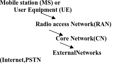
A UMTS network consist of three interacting domains; Core Network (CN), UMTS Terrestrial Radio Access Network (UTRAN) and User Equipment (UE). The main function of the core network is to provide switching, routing and transit for user traffic. Core network also contains the databases and network management functions. The basic Core Network architecture for UMTS is based on GSM network with GPRS. The UTRAN provides the air interface access method for User Equipment. Base Station is referred as Node-B and control equipment for Node-B s is called Radio Network Controller (RNC).
Mobile station (MS) or User Equipment (UE)
Radio access Network(RAN)
Core Network(CN)
ExternalNetworks (Internet,PSTN
Figure 1 UMTS architecture Basics
MBMS (Multimedia Broadcast Multicast Service)
suitable service for delivering multimedia contents simultaneously to multiple users in a bandwidth-efficient way. As an example, various IP-Multicast based data applications can be deployed over cellular net works using MBMS.
MBMS user services
There exist many services and applications that can be provided over the application independent MBMS transport. It is not necessary to standardize specific end user services because the deployment of particular applications and services over the capabilities provided by the 3GPP system is operator specific and outside the scope of standardization.
There are three types of MBMS user Service considered within this specification.
Streaming services
A continuous data flow providing a stream of continuous media (i.e. audio and video) is a basic MBMS User Service. Like digital video broadcasting, supplementary information of text and/or still images (static media) is also important.
File download services
This service delivers binary data (file data) over an MBMS bearer. An MBMS client (i.e. UE) activates an appropriate application, and utilizes the delivered data.
Carousel services
Carousel is a service that combines aspects of both the streaming and File download services described above. Similar to the streaming service this service includes time synchronization.
MBMS service architecture
Point to multipoint service exists today which allow data from a single source entity to be transmitted to multiple end points. These services are expected to be used extensively over wireless networks; hence there is a need for a capability in the PLMN to efficiently support them. The MBMS is a unidirectional point to multipoint bearer service in which data is transmitted from a single source entity to multiple recipients. It is anticipated that other services will use these bearer capabilities.
3GPP has defined two modes of operation:
The broadcast mode.
The multicast mode.
MBMS Broadcast Mode
The broadcast mode is a unidirectional point-to-multipoint transmission of multimedia data (e.g. text, audio, picture, video) from a single source entity to all users in a broadcast service area. The broadcast mode is intended to efficiently use radio/network resources e.g. data is transmitted over a common radio channel. Data is transmitted in the broadcast service area as defined by the network (Home environment). MBMS data transmission should adapt to different radio resource availability, e.g. By reducing the bit rate of the MBMD data.
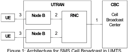
Figure gives an example of how a network can be configured to broadcast a variety of high bit rate services to users within the associated broadcast service area. Through
transport and physical s layer channels the MBMS information are send to all of user able to receive that type of services. User also know about the quality of service (QoS), service provider etc.
From the fig. it is clear that a broadcast service received by the UE, involves one or more successive broadcast sessions. A broadcast service might consist of a single on-going session (e.g. a media stream) or may involve several intermittent sessions over an extended period of time (e.g. Messages).
The broadcast mode differs from the multicast mode in that there is no specific requirement to activate or subscribe to the MBMS in broadcast mode. Than it is clear that the first stage of this type of service is service announcement and it s not for individual but all also. Then if we draw it by a fig we get.
CBC
Cell Broadcast
Center UTRAN
RNC Node B
Node B
1 2
2 3
3 UE UE
Figure 1: Architecture for SMS Cell Broadcast in UMTS
Here the Session Start means is the point at which the BM-SC is ready to send data. Similarly Session Stop means a point at which the BM-SC determines that there will be no more data to send for some period of time. At Session Stop, the bearer resources are released.
Whereas MBMS notification is notification is nothing but a information which informs the UEs about forthcoming (and potentially about ongoing) MBMS multicast data transfer.
Multicast Mode
The multicast mode allows the unidirectional point-to-multipoint transmission of multimedia data (e.g. text, audio, picture, video) from a single source point to a multicast group in a multicast service area. The multicast mode is intended to efficiently use radio/network resources e.g. data is transmitted over a common radio channel. Data is transmitted in the multicast service area as defined by the network (Home environment). A multicast service might, consist of a single on-going session (e.g. a multimedia stream) or may involve several intermittent multicast sessions over an extended period of time (e.g. Messages). In the same way we also draw the multicast mode. The UE starts receiving the multicast data associated with the multicast group(s) it has joined.
The user may choose to stop receiving a selected multicast service and thereby leaves the multicast group. The user may also select to continue (or not) to receive service announcements for this multicast subscription group. The multicast mode defined in this specification should not be confused with IP multicast. Multicast mode shall be inter-operable with IETF IP multicast. This could allow the best use of IP service platforms to help maximize the availability of applications and content.
mode generally requires a subscription to the multicast subscription group and then the user joining the corresponding multicast group.
Reception of multicast services cannot be guaranteed over the access network. For many applications and services guaranteed data reception may be carried out by higher layer services or applications, which make use of MBMS. MBMS Radio Network Architecture
In the previous section we already get the basic architectural concept about MBMS and from which it s clear to us that the MBMS bearer service offers two modes:
Multicast mode
Broadcast mode
MBMS architecture enables the efficient usage of radio-network and core-radio-network resources, with an emphasis on radio interface efficiency. The existing PS domain functional entities (GGSN, SGSN, UTRAN, GERAN and UE) are enhanced to provide the MBMS bearer service. A particular instance of the MBMS bearer service is identified by an IP multicast address and an APN network Identifier.
A functional entity, the broadcast multicast service center (BM-SC) provides a set of functions for MBMS user services.BM-SC functions for different MBMS user services may be supported from the same or different physical network elements.
The UTRAN consists of a set of Radio Network Subsystems connected to the Core Network through the Iu. A RNS consist of a Radio Network Controller one or more Node Bs. The GGSN establishes the MBMS bearer context and registers at BM-SC.the GGSN reports to the BM-SC the successful user specific MBMS multicast activation (join) to allow the BM-SC to synchronize the BM-SC MBMS UE context with the MBMS UE contexts in the SGSN and GGSN. The functionality of other function point (UE, GGSN, SGSN) are already discuss in earlier section. Here we knew a functional entity is BM-SC.
BM-SC
A BM-SC specific functional entity Broadcast Multicast Service Centre (BM-SC) supports various MBMS user service specific services. The BM-SC is a functional entity, which multi exist for each MBMS User Service.
i. Membership function
The BM-SC Session and Transmission Function provide authorization for UEs requesting to activate an MBMS service. The Membership function may have subscription data of MBMS service users.
ii. Session and Transmission function
The BM-SC Session and Transmission Function should be able to schedule MBMS session retransmissions, and label each MBMS session with an MBMS Session Identifier to allow the UE to distinguish the MBMS session retransmissions. The BM-SC Session and Transmission Function allocate TMGIs.
iii. Proxy and Transport function
The BM-SC Proxy and Transport Function is a Proxy Agent for signaling over Gmb reference point between GGSNs and other BM-SC sub-functions (Membership function, session function).
It also be able to handle when a BM-SC dealing with more than one physical network element and it is common to all that it is a intermediate device to sending data from BM-SC to GGSN.
iv. The BM-SC service announcement function shall be able to provide service announcements for multicast and broadcast MBMS user services. Announcement function provide to the UE about the MBMS session descriptions, means everything specifying about a particular services even different services also specify the MBMS sessions to be delivered as part of an MBMS user service (e.g. multicast service identification, addressing, time of transmission, etc.).
The following mechanisms should be supported for service announcement SMS (point-to-point)-
SMS-CB cell broadcast.
URL (WAP, HTTP)
PUSH mechanism (WAP push) MBMS Security Function
MBMS user services may use the security functions for integrity and / or confidentiality protection of MBMS data. The MBMS security function is used for distributing MBMS keys (key Distribution Function) to authorized Use. SGSN
The SGSN s role within the MBMS architecture is to perform MBMS bearer service control functions for each individual UE and to provide MBMS transmissions to UTRAN/GERAN.
The SGSN shall be able to indicate its MBMS support to the UE as well as it shall be able to synchronies with the UE, which of the UE s contexts are still active. The SGSN shall be able to establish Iu an Gn bearers shared by many users upon receiving a session start from the GGSN. Likewise, the SGSN shall be able to tear down these bearers upon instruction from the GGSN.
GGSN
The GGSN role within the MBMS architecture is the serve as an entry point for IP multicast traffic as MBMS data. Upon notification from the BM-SC the GGSN shall be able to request the establishment of a bearer plane for a broadcast or multicast MBMS transmission. Further, upon BM-SC notification the GGSN shall be able to tear down the established bearer plane. Bearer plane establishment for multicast services is carried out towards those SGSNs that have requested to receive transmissions for the specific multicast MBMS bearer service.
UTRAN
UTRAN nodes are responsible for efficiently delivering MBMS data to the designated MBMS service area. The UTRAN shall support the initiation and termination of MBMS transmissions by the core-network. Further, the UTRAN shall be able to receive MBMS data from the core-network over Iu bearers shared by many UEs. The UTRAN shall be able to transmit MBMS user service announcements, paging information and support other services in parallel with MBMS. UTRAN consists of several radio network controllers (RNC) and their associated Node-B s. Wide band CDMA technology was selected to tor UTRAN air interface.
MBMS Procedure Overview for Broadcast Mode In the network architecture we see that in between UE to BM-SC there are some entity function, which are working to send the MBMS information.
Each entity function does their work in few waterfall steps. In each step they do their work for a MBMS services. But we have two different mode of operation (multicast, broadcast) and see the steps of MBMS procedure for the each mode.
Audio, picture, video) from a single source entity to all users in a broadcast service area, then there will be not very much changes are made in MBMS service provision in broadcast mode only one change is shown in the first stage means subscription are not present as the data send to all users.
Service announcement
MBMS user service announcement/discovery mechanisms shall allow users to request or be informed about the range of MBMS user services available. Service announcement is used to distribute to users information about the service, parameters required for service activation (e.g. IP multicast address(es)) and possibly other service related parameters (e.g. service start time). Using SMS cell broadcast, PUSH mechanism (WAP, SMS-PP, MMS), URL (HTTP, FTP) etc, serine announcement are deliver to UE.
Joining
Joining is the process from the user by which the users subscribes or activate MBMS multicasting and join in a group or becomes a member of this group. So that the user indicates to the network that he/she wants to receive the service.
Session Start
Session Start is the point at which the MB-SC is ready to send data. Session start occurs independently of activation
of the service of the service be the user for that a given user may activate the service before or after session start. MBMS notification
Informs the UEs about forthcoming and potentially about ongoing MBMS multicast data transfer and of an upcoming change in critical MCCH (MBMS point-to-multipoint Control Channel) information. It is part dealing when a UE activate MBMS service but any of the services that UE gas joined or interested in broadcast mode, is not being, UE monitor MICH to find modifications in the MCCH. In the time there present transmitted three physical channels as MTCH, MCCH, MSCH etc. in point-to-multipoint transmission (p-t-m) channel structure point-to-multipoint transmission is use to transfer MBMS specific control/user plane information between the network and several UEs in RRC connected or Idle Mode. It is used for broadcast or multicast mode of MBMS the logical channels are as below.
Data transfer
It is the phase when MBMS data are transferred to the UEs.
Session stop
It is the point at which the BM-SC determines the there will be no more data to send for some period of time this period being long enough to justify removal of bearer resources associated with the session. At session stop, the bearer resources are released.
Leaving
Leaving (i.e. MBMS multicast deactivation by the user) is the process by which a subscriber leaves or stops being a member of a multicast group, in other word it can be said that the user no longer wants to receive multicast mode data of a specific MBMS bearer service.
Logical channels
This logical channel is used as control plane information between network and use in RRC connected or Idle Mode and is sent to use in a cell with an activated (joined) MBMS service.
MBMS point-to- multipoint control channel (MCCH)
The MBMS is always mapped to one specific FACH in the S-CCPCH as indicated on the BCCH. In case of soft combining, the MCCH is mapped to a different S-CCPCH(CCTrCH IN TTD) then MTCH. MCCH deals with system info block. It have many service info as
MBMS modification service info
MBMS unmodification service info
MBMS general service info
Only in downlink, MCCH can be mapped to FACH to connections between logical channels and transport channels exist.
MBMS point-to-multipoint Traffic Channel (MTCH) The user plane information on MTCH in MBMS service specific and is sent to UEs in a cell with an activated MBMS service. The MTCH is always mapped to one specific FACH in the S-CCPCH as indicated on the MCCH. A MCCH header is used for logical channel type identification.
It is used to scheduling between network and UEs in RRC Connected or Idle Mode. The MSCH is always mapped to one specific FACH in the S-CCPCH as indicated on the MCCH. The MSCH is mapped to a different FACH than MTCH. MAC header to identify MSCH logical channel type.
FACH is used as a transport channel for MTCH, MSCH AND MCCH. SCCPCH is used as a physical channel for FACH carrying MTCH or MCCH or MSCH. The mappings seen from the UE and UTRAN sides are shown in figure.
There also utilizes a new MBMS specific channel which is used as an indicator to indicate the information present or not. If NI is 1 then search in MCCH and map to the MTCH. It is used when change is made in the service information. Work intention
My work intention to delivering a group of individual user information within a MBMS stream. Individual user data can be text, image or any other format. User get information as a MBMS service stream data and among the more data he/she only receive his/her data.
Design Considerations
MBMS broadcast mode may be used to deliver data items for individual users in a bandwidth efficient way. If similar data for every individual user is to be delivered separately, PDP context/SMS/MMS contexts are to be established for each individual user, which involves signaling overhead. No such overhead is necessary for MBMS broadcast mode. Individual user data items of similar nature and size are collated into a combined data stream. That stream is to be delivered using MBMS broadcast to multiple users. Individual user data is uniquely identified by a within the sequence number range. It is not bandwidth-efficient to include the sequence number explicitly along with each data. Hence there must be a status indication for every user in the form of a bitmap to indicate presence/absence of data. The status indication should be broadcast more often than the data stream itself. Each indicated in the status message, it should listen to a part of the combined data stream and be able to extract the corresponding data. A basic simulation model of MBMS broadcast should include simulation of a subset of MCCH and MSCH information. A socket programming setup using an iterative server with multiple client support is to be used to simulate the network and UE behavior. Data units are transmitted with a pre-defined clock rate from the server. Each unit includes a System Frame Number (SFN) count (from 0-4095). Actual MCCH and MSCH messages are Abstract Syntax Notation (ASN.1) encoded. In absence of such encoder and decoder, only a subset to parameters have been chosen, and the structures themselves are transferred from server to UE client on designated System Frame Numbers (SFN). MTCH data is segmented into unacknowledged mode RLC PDUs. Those RLC PDUs are transmitted in the designated SFNs as per the scheduling information of MSCH data.
Design and Implementation Description
Simulation Setup
Network and UE functionalities are simulated using socket connections between an iterative server and multiple clients respectively. Each client simulates a user. So the simulation step up first sends a MBMS message structure which is union of a SFN variable and another message structure in which MCCH, MSCH and MTCH messages are act as a structure member. This message is transmitted by the server in a pre-set clock period. After each clock period, a local SFN counter is incremented as SFN = (SFN+1) mod 4096. This simulates radio frames in the Uu interface. MCCH configuration message: In real scenario, MCCH configuration for MBMS broadcast is included in system information blocks received though BCH. In the simulation setup, this is sent to each client asynchronously as this model does not simulate system information (Broadcast Channel) reception. Its contents are MCCH Modification Period and Repetition period.
MCCH message: The structure is transmitted by the server in each instant which satisfies SFN mod 2(m-r) = 0, where m-modification period coefficient, r-repetition period coefficient. It s content MSCH configuration.
MSCH Scheduling information
For FDD, scheduling information is provided starting at (SFN (SCTO div 10ms)) mod
MSCH_REP=MSCH_OFF For TDD, scheduling information is provided starting at SFN mod
MSCH_REP=MSCH_OFF Scheduling period
The period, in number of frames, between MBMS scheduling messages (MSCH_REP) Scheduling offset
The position of MBMS scheduling messages relative to timing of the corresponding cell(MSCH_OFF) Figure MSCH Configuration
MSCH message: This structure is transmitted in each instant where SFN = SFN mod MSCH_REP = MSCH_OFF. Its contents are start of the session, duration of the session transmission ID and as more than one service may be present then a service list also is it s contain. Service scheduling info list
MBMS Transmission identity
Start
Indicates the start of the transmission relative to the start of the TTI in which the MBMS scheduling
information message was received. In number of radio frames.
Duration In number of radio frames.
MTCH message: It basically made by two MBMS messages, one is Bitmap stream, and another is data stream. The stream is segmented as per RLC Pdu sixe (42 bytes). One or more PDUs are transmitted in each SFN. Its content is a union of a variable, to maintain the list and a byte stream structure in which a integer type variable and PDU byte array are two structure member.
Network Server
Each user has their corresponding data then we consider a sequence number to identify each individual user data. Corresponding each sequence number, it would be check if data for that sequence number is present in the long stream or not. A bitmap is used to represent presence/absence of data, with each bit corresponding to a sequence number. For creating the bit-map, convert the corresponding sequence number into byte and performed the bitwise OR operation to set the corresponding bit 1 after seeing the data s presence indication comparing with the data file otherwise set 0 and after completing this operation for each user, finally get the bitmap in matrix form.
But in the bitmap there data part is not added with this array. Because for reliability condition, means it not sure that each time user get the write bitmap. To avoid this situation simply retransmit the bitmap again-again to make the system more reliable. If the bitmap array is too much long then there may be occur some difficulties in retransmission.
The data part don t take the as a whole but also take its fragmented part. It is done to improve the searching efficiency. For segmentation purpose, simply take the number of valid data and store in one packet according to the PDU. To identify the valid data for each user perform bitwise AND function to check 1 as a present data each data packet identified by a different ID.
UE Client
After set up the connection through TCP/IP socket connection from the client side the client only after giving the serial number corresponding to the sequence number, check the first bitmap. If the data is present then by the MCTH getting the message-ID and get the data also. Checking the bitmap:
Firstly as mention earlier the stream is fragmented means stream is formatted. For this function I first read the value of sequence number and corresponding data value from a file. Then an insert function is calling to bind the sequence number, user data. Before adding the sequence number, I convert it byte format because data is in byte-stream. Retrieval of user data:
When the sequence number is enter the first subtract it from the start number and convert it to byte stream and check the corresponding bitmap it s 1 or 0 and get the data (if corresponding value is 1). For checking the absence or presence we simply apply the same way means performed logical AND operation and if it s value >0 then data present otherwise not and after convert it in byte stream, store in a array and concatenate it with each sequence number. Then for every sequence number their present data absence or presence byte stream in one array. In this way the bitmap is ready for checking purpose.
CONCLUSION
In conclusion it may be state that, the program framed in this work may be come in to effect to any data dissemination process/centers for their help if the concerned process/centers is rightly able to follow the construction of the program along with the simulation effect. The users would like to retrieve their target information within minimum time and also the system/program should be as simple as possible. In another ways, this may be state that the user s community would not like to spare any more time for understanding the programming language and such others protocols relating to retrieving any required information. In this juncture, the present study may be appeared to the data dissemination centers as helpful tools to reaching out to any solution. Apart from this, the present work has also opened a new dimension for research work to edit the existing simulation effect. At the same time the work do not claim that it is a complete one, as it is quite impossible to make any in depth study within any short period of time. Finally, if this work is able to satisfy the lacks of the existing programming and simplify the data dissemination process then only my effort should be successful.
REFERENCES
[1]. 3GPP TS 22.146 V7.2.0 (2006-09): 3rd Generation Partnership Project; Technical Specification Group Services and System Aspects; Multimedia Broadcast/Multicast Service; Stage1(Release 7) [2]. 3GPP TS 22.246 V7.3.0 (2007-06): 3rd Generation Partnership
Project; Technical Specification Group Services and System Aspects; Multimedia Broadcast/Multicast Service(MBMS) user services; Stage1(Release 7)
[3]. 3GPP TS 23.246 V7.3.0 (2007-06): 3rd Generation Partnership Project; Technical Specification Group Services and System Aspects; Multimedia Broadcast/Multicast Service(MBMS); Architecture and functional description(Release 7)
[4]. 3GPP TS 25.346 V7.4.0 (2007-06): 3rd Generation Partnership Project; Technical Specification Group Radio Access Network; Introduction of the Multimedia Broadcast Multicast Service (MBMS) in the Radio Access Network (RAN); Stage2(Release 7) [5]. www.medialab.sonera.fi-mobaile multicast broadcast service (white
paper).
[6]. www.umts-forum.org-3G/UMTS towards mobile broadband and personal Internet.
[7]. 3GPP TS 25.346, Introduction of Multimedia Broadband/Multicast Service (MBMS) in the Radio Access Network (RAN); Stage2, 2006.
[8]. www.books.ci.in-UMTS networks By Heikki Kaaranen, Ari Ahtiainen, Lauri Laitinen, Siamak Naghian, Valtteri Niemi.
[9]. www.wikipedia®Public_land_mobile_network_files.
[10].WS 03/04, TKN TU Berlin, Cornelia Kappler Course UMTS Network, III. UMTS Architecture.
[11].Introduction of the Multimedia Broadcast Multicast Service (MBMS); in the Radio Access Network (RAN); Stage 2 (Release 7), 3GPP TS 25.346 V7.4.0 (2007-07-25).
[12].MULTIMEDIA Broadcast Multicast Service (MBMS); UTRAN/GERAN Requirements, 3GPP TR 25.992 V7.0.0 (2007-07-31).
[13].P. Garg et al., Using 802.11e MAC for QoS over Wirless, Proc. Of 2003 IEEE International Conference on Communication (ICC 2003), 2003, pp. 537-542.
[14].Multimedia Broadcast/Multicast Service (MBMS); Architecture and functional description (Release 7), 3GPP TS 23.246 V7.3.0 (200-06-19)