R E S E A R C H
Open Access
An approach to the modulation recognition of
MIMO radar signals
Xiaojing Wang
*, Ying Xiong, Bin Tang and Yunhao Li
Abstract
Multiple-input multiple-output (MIMO) radar is a new radar system and draws more and more attentions in recent years. Along with the development of MIMO radar, the MIMO radar countermeasure is brought into being. Since the
modulation recognition is of great significance in the electronic reconnaissance, this article presents a modulation recognition method for the signals of the emerging MIMO radar. Signals of interest are classified into three categories based on instantaneous autocorrelation spectrum analysis first. Then non-coding MIMO radar signals are discriminated by spectrum analysis, and coding MIMO radar signals are recognized by source number estimation algorithm. Meanwhile, the sub-carrier numbers of some kinds of MIMO radar signals are estimated. Simulation results verify the effectiveness of the method and the overall correct recognition rate is over 90% when the value of SNR is above 0 dB.
Keyword:Modulation recognition, MIMO radar signal, Instantaneous autocorrelation spectrum, Source number estimation, Sub-carrier number
1. Introduction
The concept of multiple-input multiple-output (MIMO) radar, which comes from communication system, has drawn considerable attention in recent years from both re-searchers and practitioners [1]. It builds a bridge between the research of radar and communication. MIMO radar is generally divided into two categories, one is statistical MIMO radar with widely separated antennas, and the other is coherent MIMO radar with co-located antennas. In both categories of MIMO radar system, multiple trans-mit antennas are employed to etrans-mit specific waveforms and multiple receive antennas process the reflected signals jointly. MIMO radar offers quite a lot of advantages, such as more degrees of freedom, higher resolution, and sensi-tivity and better parameter identifiability [2-4]. These ad-vantages mostly result from waveform diversity. Due to the waveform diversity, intercepted signals in reconnaissance receiver are multi-carrier signals. Accordingly, signal detec-tion, parameter estimadetec-tion, and modulation recognition are vastly different from single-carrier (SC) signals adopted by conventional radars. As a result, it poses an emerging and powerful challenge in electronic countermeasures.
In order to occupy an advantageous position in the future electronic warfare, we need to investigate the feature of MIMO radar and study its electronic coun-termeasures. This article discusses the modulation recognition of MIMO radar signals, which is of great significant in the electronic reconnaissance. Since there are some actual difficulties in engineering prac-tice for statistical MIMO radar, hereinafter we focus on coherent MIMO radar.
The reconnaissance technology of MIMO radar is rarely studied in the published literatures. Liang [5] and Xing et al. [6] discussed about the electronic reconnaissance technology of MIMO radar at system design and concep-tual angle. Tang et al. [7] provided a new reconnaissance technology for MIMO radar. The aim of the article is to discriminate whether it is MIMO radar by the number of orthogonal waveforms. However, the location of suspicious radar is as known information, which is usually unknown in actual environment. Besides, Chen et al. [8] and Hassan et al. [9] were about the modulation identification of MIMO system, which is adopted in the wireless communi-cation field. In [8], the combination of second- and fourth-order of cumulants was used as the feature parameters, which were utilized to discriminate the orthogonal fre-quency division multiplexing signals from the SC modula-tions. In [9], high-order statistics and neural networks were
* Correspondence:[email protected]
School of Electronic Engineering, University of Electronic Science and Technology of China, Chengdu, People’s Republic of China
employed to identify the modulation type of MIMO system with and without channel state information.
Based on the instantaneous autocorrelation spectrum of received signals, an approach to the modulation rec-ognition of MIMO radar signals is proposed in this art-icle. For conventional radar, SC signal is often adopted, such as monopulse (MP) signal, linear frequency modu-lation (LFM) signal, phase-coded (PC) signal, and frequency-coded (FC) signal. For MIMO radar, four basic modulation types [10-12] are involved in this art-icle: MP-MIMO (orthogonal MP signal in MIMO radar), LFM-MIMO (orthogonal LFM signal in MIMO radar), PC-MIMO (orthogonal PC signal in MIMO radar), and FC-MIMO (orthogonal FC signal in MIMO radar). Here, we need to discriminate MIMO radar signal from con-ventional radar signal and recognize the modulation type of MIMO radar signal.
The remainder of this article is organized as follows. In Section 2, four basic emitting signal models of MIMO radar are given. The recognition method is introduced in Section 3. Instantaneous autocorrelation spectrum analysis, frequency spectrum analysis, and source num-ber estimation algorithm (SNEA) are involved in this section. Simulation results are given in Section 4 and conclusions are drawn in Section 5.
2. Signal models
Assuming that the transmitting arrays of MIMO radar are uniform linear arrays (ULA), in the reconnaissance receiver, the four basic received MIMO signal models can be expressed as follows [10-12].
sMPMIMO½ ¼n where exp() denotes the exponential function, M is the number of sub-carriers of MIMO radar signal, f0 is the
carrier frequency, fp= 1/T and △ϕ denote the
fre-quency interval and phase difference between adja-cent sub-carriers, respectively, u denotes the chirp rate, I is the code length of coding signal,Ts= 1/fs is
the sampling interval, fs is the sampling rate,
φmð Þi∈ 0;2π
L;. . .;ðL1Þ:2Lπ
denotes the phase of
sub-pulse i of the mth component, fmð Þi ∈ 0;T11;. . .; n
I1
ð Þ:1
T1g denotes the frequency of sub-pulse i of the mth component, Lis the distinct phase number in PC-MIMO, T and T1 represent the pulse and sub-pulse width, respectively, g(t), 0≤t≤T1 is the enve-lope function. Particularly, to ensure the orthogonality of components, ∅m(i) and fm(i) are usually obtained
by intelligent algorithm, such as genetic algorithm and simulated annealing algorithm.
3. Recognition method
For the sake of convenience,Sset is employed:S= {MP-MIMO, LFM-{MP-MIMO, PC-{MP-MIMO, FC-MIMO and SC signals}. This section will be divided into three parts. The first part classifiesSset signals into three categories: SC signals S0= {SC signals}, non-coding MIMO radar signals S1= {MP-MIMO, LFM-MIMO} and coding MIMO radar signals S2= {PC-MIMO, FC-MIMO}. S1 and S2 set signals are recognized in second and third parts, respectively.
3.1 Instantaneous autocorrelation spectrum analyses The signal pulse parameters can be extracted from in-stantaneous autocorrelation features. Since the fre-quency characteristics of different modulation types are diverse, instantaneous autocorrelation function can be utilized to the modulation recognition of MIMO radar signals. The instantaneous autocorrelation function is defined as
r n½ ;Δn ¼s n½ þΔns½ n ð5Þ
3.1.1. S1/(S0,S2) selection
(a)S1set signals analysis
For convenience, letΔn= 1, then we can get
Accordingly, the signal term is get as
exp j2πff0
The cross term is obtained as
exp j2πf0þfkfpn
From the above, the moduli of signal term and cross
term are sinðMπfp=fsÞ
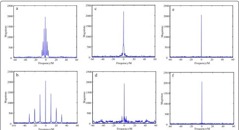
Figure 1b shows the instantaneous autocorrelation spectrum of LFM-MIMO signal. The simulated MIMO radar has a ULA comprising four transmitting antennas with half-wavelength spacing between adjacent antennas. The simulated SNR is 5 dB. By the way, for the other parts of Figure 1, the simulation conditions are the same. For Figure 1b, the maximum peak results from signal term while other peaks are from cross terms. As we can see, the biggest cross term appears as the second peak in the autocorrelation spectrum. To extract signal features, we define the feature parameter: the ratio of second peak and maximum peak, which can be expressed as follows:
RAmplitute¼
If u= 0, Equation (7) is the instantaneous autocorrel-ation function of MP-MIMO. Since u is not related to (10), MP-MIMO and LFM-MIMO have the equivalent values ofRAmplitute. Comparing Figure 1a with b, the fact is verified since the values of every peak are the same. Given the value ranges of parameters in Equation (10), the minimum value ofRAmplitutecan be obtained.
In addition, by searching the peaks of instantaneous autocorrelation spectrum of non-coding MIMO radar signal, the number of sub-carriers can be obtained. For Figure 1, the simulated MIMO radar has four
transmitting antennas. That is, the sub-carrier number is four. Seven peaks can be seen in Figure 1a,b. Six of them, resulted from cross terms in (9), are symmetrical. Together with the single frequency at center, the distinct frequency number is four. That is, the sub-carrier num-ber is four for the received MIMO radar signal, which is equal to the actual sub-carrier number of non-coding MIMO radar signal. For the instantaneous autocorrel-ation spectrum of non-coding MIMO radar signal, sup-posing that the number of peaks is a, the sub-carrier number is (a+ 1)/2.
Meanwhile, some signal modulation parameters of non-coding MIMO radar signal can be got from the in-stantaneous autocorrelation spectrum. For example, the chirp rateuand the frequency interval between adjacent sub-carriers fp. They can be estimated from the location
of peaks.
(b)S2set signals analysis
For PC-MIMO and FC-MIMO, substituting Equations (3) and (4) into Equation (5), respectively, the instantan-eous autocorrelation functions are as follows:
rPCMIMO½n;1 ¼ exp j2π
where the superscript of∅ and fdenote the location of the code.
For Equation (11), since φnþ1
m φnl ¼const in a
sub-pulse,rPC-MIMO[n,1] is constant in a sub-pulse. Ifn is the last sampling points of a sub-pulse, thenn+ 1 is in the next sub-pulse. So, the value of φnmþ1φnl
suddenly changes and mutations appear in sub-pulses junctions. The con-stant values result in zero frequency. The mutations will bring about some low frequencies, the amplitudes of which are very small compared with the zero frequency. That is, only one obvious peak appears at the zero frequency in the frequency spectrum of PC-MIMO.
For Equation (12), there areM ×M components in a sub-pulse.Mcomponents, which are fromfnþ1
m fln¼0
in the case of m= 1 in a sub-pulse, result in zero fre-quency. If m≠l, then fnþ1
m fln¼Δf in a sub-pulse.
frequencies. Considering the symmetry, there are
M2M
ð Þ.
2 positive frequency components. M – 1
com-ponents have the same frequency in the worst case. However, since the code length Iis far greater than the number of sub-carrier M generally, the codes of each component are different in the same sub-pulse. So, the values of fnþ1
m fln
in a sub-pulse are diverse. The other sub-pulses as well. That is, the energies of the cross terms almost cannot be superimposed. Only one obvious peak appears at the zero frequency in the fre-quency spectrum of FC-MIMO.
The instantaneous autocorrelation spectrums of PC-MIMO and FC-PC-MIMO signals are shown in Figure 1c,d, respectively. As can be seen, most of the energies gather at the zero frequency while some appear at low frequencies for both PC-MIMO and FC-MIMO, which verify the above analysis. As a result, values ofRAmplitutefor coding MIMO radar signals are very small, which are less than the value of non-coding MIMO signals. The same to the SC signals, which can be seen in Figure 1e,f.
Consequently, taking the ratio of second peak and max-imum peak as the feature parameter,S1signals are discrim-inated fromS0andS2set, which is expressed as follows:
RAmplitute ≥ γ⇒S1
RAmplitute<γ⇒S0=S2 ð13Þ
whereγis the value of the threshold.
Assuming that 4≤M≤50, 0.005≤fp/fs≤0.02, which
satisfy most of the signal environment, the minimum value of Equation (10) is 0.7502. That is, for non-coding MIMO radar signal, the value ofRis always greater than 0.7502. Obviously, forS0orS2set signals, the value ofR is smaller than 0.7502. As a consequence, 0.75, the value of the threshold, permits classifying between S1set and other modulation types.
3.1.2. S0/S2selection
LetΔn= 0, thenr[n, 0] =s[n]s*[n].
For SC signals,rSC[n, 0] = 1. As a result, the frequency ofrSC[n, 0] is zero.
For coding MIMO radar signals, according to (3) and (4), we can get the r[n,0] of PC-MIMO and FC-MIMO signals, which can be expressed as follows:
rPCMIMO½n;0 ¼
From Equations (14) and (15), we can see that there are some mutations in the correlation function. As a result, they will bring about some low-frequency com-ponents. Since the frequency of rSC[n, 0] is zero, this
allows us to discriminate SC signals from coding MIMO radar signals.
Employing Fourier transform on the r[n,0], which is obtained from S0 and S2 set signals, we can obtain its positive frequency spectrum.
Rr n½;0½ ¼k jDFTðr n½ ;0Þj; k
¼1;2;. . .;NDFT=2 ð16Þ
whereNDFTdenotes the points of discrete Fourier trans-form (DFT). Then we divide the positive frequency into two segments. One is the low-frequency segment; the other is the rest part.
R1r n½ ;0½ k; k¼1;2;. . .;N1
R2r n½ ;0½ k; k¼N1þ1;N1þ2;. . .;NDFT=2 ð17Þ
After that, we define the feature parameterRmeanas
Rmean ¼
MeanR1r n½;0 Mean R2r n½;0
ð18Þ
where Mean() is the mean function. Since rSC[n, 0] = 1 for SC signals, the frequency of rSC[n, 0] is zero, which
implies that R1r[n,0] and R2r[n,0] are only affected by noise. Thus,Rmeanapproximately equals 1 in the additive white Gaussian noise (AWGN) condition. For coding MIMO radar signals, according to Equations (14) and (15), there are a few mutations in ther[n,0]. Hence, they will lead to some low-frequency components, the values of ratioRmean of coding MIMO radar signals are always
greater than 1. This permits us to discriminate SC sig-nals from coding MIMO radar sigsig-nals.
Consequently, setting proper thresholds ς, S2 set sig-nals are discriminated from S0 set signals, which is expressed as follows:
Rmean≥ ς⇒S2
Rmean<ς⇒S0 ð19Þ
MP-MIMO/LFM-MIMO selection
According to the first part,Sset signals are divided into three categories. To recognize the modulation type of MIMO radar signal, we need to keep working on S1set and S2set signals. In this part, our attention is focused on theS1set. The goal is to discriminate MP-MIMO sig-nal from LFM-MIMO sigsig-nal.
Selecting two different lengths of time window for the signal and employing DFT on them, we can get
Sa½ ¼k jDFTðsa½ nÞj; sa½ ¼n s n½ ;n¼1;2;. . .N2
Sb½ ¼k jDFTðsb½ nÞj; sb½ ¼n s n½ ;n¼1;2;. . .N;N>2N2
ð20Þ
As can be seen in (20), sa is contained in sb and the
sampling length ofsbis greater thansa.
If the maximum value of Sa is noted by Max(Sa), and
the corresponding frequency number is kmax, then the value of Sb[kmax] is obtained. We define the following feature parameter
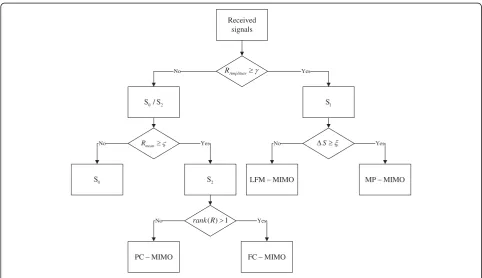
Received signals
Amplitute
R Yes
1 S
No
0 2
S / S
mean
R Yes
No
2 S 0
S
S Yes
No
MP MIMO
LFM MIMO
Yes No rank R( ) 1
FC MIMO
PC MIMO
ΔS¼Maxð Þ Sa Sb½kmax ð21Þ
The frequency of MP-MIMO signal is not affected by the time while LFM-MIMO signal is modulated along time. That is, for MP-MIMO signal, the energy at a fre-quency is increasing with the increase of sampling points while the LFM-MIMO is not, for the energy present at the extra frequencies. Setting a proper threshold ξ, MP-MIMO signal and LFM-MP-MIMO signal are separated.
ΔS ≥ξ⇒MPMIMO
ΔS<ξ⇒LFMMIMO ð22Þ
3.3. PC-MIMO/FC-MIMO selection
The SNEA is employed to recognize the signals ofS2set in this part. For the sake of convenience, only the first code length signal is chosen. That is, the signal section going to be analyzed iss(n),n<T1/Ts. We first construct
and then get its autocorrelation matrix
R¼ 1
For PC-MIMO signal, according to Equation (3), we have
sm½nþk ¼ expðj2πf0kÞsm½ n ð25Þ
To simplify expressions, Ts= 1 is employed in the
calculation.
Obviously, rank(A0) = 1, where rank(*) denotes the rank of matrix *. Observing Equation (23), we have Sob=A0S0. ThenR¼A0S0SH0AH0=N. According to the nature of rank,
it is easy to get that rank(R) = 1 for PC-MIMO signal.
Table 1 Simulation parameters
Simulation parameters f0(MHz) fs(GHz) T (μs) u (THz/s) T1PC(μs) T1FC(μs) L
Condition 1 100 0.5 5 2 0.25 0.25 4
Condition 2 100 2 5 4 0.05 0.1 6
Lis the distinct phase number of PC/PC-MIMO,T1PCandT1FCare the sub-pulse width of PC/PC-MIMO and FC/FC-MIMO, respectively. The simulation results are
based on 1000 Monte Carlo trials for each modulation type and each SNR value. Particularly, we consider that SC signals are correctly recognized when the simulation results areS0set signal but not the exact modulation type.
Table 2 Confusion matrices forΩ1
Input modulation
Table 3 Confusion matrices forΩ2
For FC-MIMO signal, according to (4), we have
sm½nþk ¼ expfj2π½f0þfmð Þnkgsm½ n ð28Þ
Let
A1¼
1 1 ⋯ 1
ej2πðf0þf1Þ1 ej2πðf0þf2Þ1 ⋯ ej2πðf0þfMÞ1
⋮ ⋮ ⋯ ⋮
ej2πðf0þf1ÞðMr1Þ ej2πðf0þf2ÞðMr1Þ ⋯ ej2πðf0þfMÞðMr1Þ 2
6 6 4
3 7 7 5∈CMrM
ð29Þ
S0¼
s1½ 1 s1½ 2 ⋯ s1½ N s2½ 1 s2½ 2 ⋯ s2½ N
⋮ ⋮ ⋯ ⋮
sM½ 1 sM½ 2 ⋯ sM½ N 2
6 6 4
3 7 7
5∈CMN ð30Þ
where f1, f2,. . ., fM denote the first frequency code of
each component. To ensure the orthogonality between components, the values of f1, f2,. . ., fM are not equal.
According to Equations (29) and (30), we haveSob=A1S0
-5 0 5 10 15
0 0.2 0.4 0.6 0.8 1
SNR/dB
Recognition rate MP-MIMO (4)
LFM-MIMO (4) PC-MIMO (4) FC-MIMO (4) MP LFM
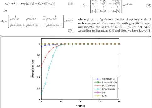
Figure 3The recognition rate versus SNR (on the condition of 1 forΩ1).
-5 0 5 10 15
0 0.2 0.4 0.6 0.8 1
SNR/dB
Recognition rate
MP-MIMO (4) LFM-MIMO (4) PC-MIMO (4) FC-MIMO (4) MP LFM
and R¼A1S0SH0AH1=N for FC-MIMO signal. Substitut-ing Equation (4) intoS0, we can obtain that rank(S0) = M. If Mr>M, then rank(A0) =M, and so rank(R) =M for MIMO signal. Hence, PC-MIMO signal and FC-MIMO signal are recognized. Meanwhile, the number of sub-carriers of FC-MIMO signal is obtained by the rank ofR.
Here, Akaike Information Criterion [13] is adopted to calculate the rank of the autocorrelation matrix. By comparing the rank of autocorrelation matrix with 1, PC-MIMO and FC-MIMO are discriminated. That is
rank Rð Þ ¼1⇒PCMIMO
rank Rð Þ>1⇒FCMIMO ð31Þ
-5 0 5 10 15
0 0.2 0.4 0.6 0.8 1
SNR/dB
Recognition rate MP-MIMO (4) LFM-MIMO (8) PC-MIMO (10) FC-MIMO (12) PC
FC
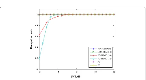
Figure 5The recognition rate versus SNR (on the condition of 1 forΩ2).
-5 0 5 10 15
0 0.2 0.4 0.6 0.8 1
SNR/dB
Recognition rate MP-MIMO (4) LFM-MIMO (8)
PC-MIMO (10) FC-MIMO (12)
PC FC
At last, the modulation recognition method can be summarized as following flowchart in Figure 2.
4. Simulation and analysis
Simulation results are shown in this section. Modulation types inSset, which are given byΩ1andΩ2, are used to test the validity of the proposed approach.
Ω1¼
MP;LFM;
MPMIMOð Þ4 ;LFMMIMOð Þ4 ;
PCMIMOð Þ4 ;FCMIMOð Þ4
8 < :
9 = ;
Ω2¼
PC;FC;
MPMIMOð Þ4 ;LFMMIMOð Þ8 ;
PCMIMOð Þ10;FCMIMOð Þ12
8 < :
9 = ;
-5 0 5 10 15
-0.05 0 0.05 0.1 0.15 0.2 0 0.3
SNR/dB
relative error
LFM-MIMO (10) LFM-MIMO (7)
MP-MIMO (7) MP-MIMO (10) FC-MIMO (7) FC-MIMO (10)
Figure 7The relative error of estimated sub-carrier numbers ofΩ3.
-5 0 5 10 15
-0.05 0 0.05 0.1 0.15
SNR/dB
relative error
LFM-MIMO (20) LFM-MIMO (17)
MP-MIMO (17) MP-MIMO (20) FC-MIMO (17) FC-MIMO (20)
The figure following each MIMO radar signal denotes the number of sub-carriers. Suppose that the received signals are imbedded in complex AWGN and are rect-angular pulse shape. Particularly, experiments are oper-ated on two different simulation conditions, which are showed in Table 1.
4.1. The classification results
First, we study the performance of the proposed classi-fier with several values of SNR. Because of lack of space, simulation results under 0 dB is selected as rep-resentatives. Confusion matrices for Ω1 and Ω2 are shown in Tables 2 and 3, respectively, on two different conditions listed in Table 1. 1000 signals are utilized for each modulation scheme.
From Tables 2 and 3, we can see that the approach based on instantaneous autocorrelation spectrum successfully classifies theSset signals into three categories. The correct classify rates are all over 90%. It shows that this approach is well prepared for the following modulation recognition. Moreover, the performance shown in Tables 2 and 3 is alike on the constant condition, which indicates that the method is unaffected by sub-carrier numbers of MIMO radar signal.
4.2. The recognition results
Figures 3, 4, 5, and 6 represent the final recognition results. As can be seen, the total recognition probability is over 90% when the value of SNR is as low as 0 dB. The results demonstrate that the modulation types are well recognized by the suggested method.
This method presents an excellent performance for non-coding MIMO radar signals, which is of high recog-nition rate even if the value of SNR is−5 dB. Comparing Figure 3 with Figure 5, the recognition performance is almost the same, which demonstrates that the sub-carrier number influences the proposed method slightly. This can also be illustrated by comparing Figure 4 with Figure 6. Comparing Figure 4 with Figure 3, the per-formance of FC-MIMO signal in low SNR slightly de-creased, which results from high code rate. The same conclusion can be obtained by comparing Figure 5 with Figure 6.
4.3. The estimation results
As is mentioned above, some parameters of MIMO radar signal can be estimated simultaneously by the recognition method. Here, the estimation results of sub-carrier numbers of non-coding MIMO radar sig-nal and FC-MIMO radar sigsig-nal are presented as rep-resentative.
The simulation is conducted on the condition 1. The sig-nals used to test areΩ3andΩ4, which can be expressed as
Figures 7 and 8 show the relative error of estimation. As can be seen, the sub-carrier numbers of MIMO radar sig-nal are almost correctly estimated when the value of SNR above 0 dB. If the values of SNR below 0 dB, the relative error of estimation is acceptable. Comparing Figure 7 with Figure 8, the relative error of Figure 8 is smaller than Figure 7. This results from the calculation methods of relative error. By the proposed approach, for the different sub-carriers, the absolute error changes slightly. Then the relative error decreases with the increases of sub-carriers.
5. Conclusions
This article presents an approach to recognize the modulation type of MIMO radar signals for the first time. Three feature parameters are proposed in the rec-ognition method. First, the intercepted signal is classified based on the instantaneous autocorrelation spectrum. Then, taking advantage of the difference in frequency domain, MP-MIMO signal and LFM-MIMO signal are discriminated. At last, SNEA is employed to recognize PC-MIMO signal from FC-MIMO signal. Besides, sub-carrier numbers of non-coding MIMO radar signal and FC-MIMO signal are estimated simultaneously. Simula-tion results verify that the proposed method can extract the features of each modulation type, and effectively recognize the signals in the given set. This result can be provided as an analysis reference for the research of MIMO radar countermeasures.
Competing interests
The authors declare that they have no competing interests.
Received: 11 December 2012 Accepted: 1 February 2013 Published: 14 March 2013
References
1. J Li, P Stoica,MIMO Radar Signal Processing(Wiley, New Jersey, 2008) 2. DW Bliss, KW Forsythe, Multiple-input multiple-output (MIMO) radar and
imaging: degrees of freedom and resolution, inProceedings of the Thirty-Seventh Asilomar Conference on Signals, Systems and Computers, vol. 1 (, California, USA, 2003), pp. 54–59. November
3. KW Forsythe, DW Bliss, GS Fawcett,Multiple-input multiple-output (MIMO) radar: performance issues, in Proceedings of the Thirty-Eighth Asilomar Conference on Signals, Systems and Computers, vol. 1 (USA, California, November 2004). pp. 310–315
4. J Li, P Stoica, LZ Xu, W Roberts, On parameter identifiability of MIMO radar. IEEE Signal Process. Lett.14(12), 968–971 (2007)
6. R-Y Xing, C-G Zhou, T-J Tong, The characteristic of foreign MIMO radar system and the space electronic reconnaissance and countermeasure. Foreign Inf. War (in Chinese)1, 38–39 (2007)
7. X-W Tang, J Tang, B Tang, A new electronic reconnaissance technology for MIMO radar, inProceedings of the 2011 IEEE CIE International Conference on Radar, vol. 1(, Chengdu, China, 2011), pp. 79–83. October
8. J Chen, Y-H Kuo, X-L Liu, Modulation identification for MIMO-OFDM signals, inProceedings of the IET Conference on Wireless, Mobile and Sensor Networks, vol. 1(, Shanghai, China, 2007), pp. 1013–1016. December
9. K Hassan, W Hamouda, I Dayoub, Blind modulation identification for MIMO systems, inProceedings of the IEEE Global Telecommunications Conference, vol. 1(, Miami, USA, 2010), pp. 1–5. December
10. B Liu, Z-S He, J-K Zeng, B-Y Liu, Polyphase Orthogonal Code Design for MIMO Radar Systems, inProceedings of the CIE International Conference on Radar, vol. 1(, Shanghai, China, 2006), pp. 1–4. October
11. B Liu, Z-S He, Orthogonal discrete frequency-coding waveform design for MIMO radar. Chin. J. Electron.25(4), 471–476 (2008)
12. B Liu,Research on generation of orthogonal waveform and signal processing for MIMO radar. Dissertation, University of Electronic Science and Technology (in Chinese), 2008
13. M Wax, T Kailath, Detection of signals by information theoretic criteria. IEEE Trans. Acoust. Speech Signal Process.33(2), 387–392 (1985)
doi:10.1186/1687-1499-2013-66
Cite this article as:Wanget al.:An approach to the modulation recognition of MIMO radar signals.EURASIP Journal on Wireless Communications and Networking20132013:66.
Submit your manuscript to a
journal and benefi t from:
7Convenient online submission
7Rigorous peer review
7Immediate publication on acceptance
7Open access: articles freely available online
7High visibility within the fi eld
7Retaining the copyright to your article