© 2015, IRJET ISO 9001:2008 Certified Journal Page 2029
COMPARISON OF CONTROL STRATEGIES OF DSTATCOM FOR
HARMONIC MITIGATION
Adarsh.P
1, Sijo george
21
PG student, Electrical department, Asiet, Kerala, India
2Asst. prof, Electrical department, Asiet, Kerala, India
---***---Abstract –
The major issue existing in the powersystem are due to the non linear characteristics and fast switching of the power electronic equipments. Power quality issues are becoming more and more relevant due to the effects that causing the power system .It leads to reduction in efficiency of the system and increase in utility costs, efficiency and cost are considered today almost at the same level. The power quality issues can be mitigated by making use of the active power filters. Among this shunt active power filter can be used for harmonic as well as reactive power compensation.
In this work two reference generation methods have been compared. Switching pulses for the inverter is derived using hysteresis PWM control and DC link voltage has been regulated using conventional PI controller.
A MATLAB program has been developed to simulate the system operation. Various simulation results are presented under steady state conditions and performance.
Key Words:
Distribution static compensator
(DSTATCOM), instantaneous reactive power (IRP)
theory, Harmonic compensation, synchronous
reference frame (SRF) theory , Sinusoidal pulse
width modulation(SPWM)
1. INTRODUCTION
The power system involves the production, Transmission and distribution of power. The main parameters that should be taken in to account are the quality of the delivered power. In recent times the use of power electronic equipments and reactive power consuming loads are widely in use, because of these loads power quality issue will arise. This will cause reduction in the utility power quality and destruction of the complete system can happen.
There are a lot of power qualities issues among them sag& swell, harmonics are the major issues. Basically harmonics is the integral multiple of fundamental frequency of current of voltage. The presence of harmonics in the system is mainly due the effect of nonlinear loads. There are two types of loads linear load
and non linear loads. Linear loads are something which works with sinusoidal voltage and current and did not cause harmonic issues. Nonlinear loads will draw some harmonic component of current from the source along with the fundamental component, so the source current will be disturbed due to harmonics. In order to solve this problem harmonic component of current should be provided from some other external sources. This can be effectively done by active power filters. Among them shunt active power filter can provide better compensation to harmonics. It will inject the harmonic component of current at the point of common coupling so that the source will be free from supplying the harmonic component of current to satisfy the requirements.
1.1
Dstatcom principle of operation
Fig -1: Principle of operation
© 2015, IRJET ISO 9001:2008 Certified Journal Page 2030
2. SYSTEM CONFIGURATION
The fig 2 shows an uncompensated system. This is a three phase three wire system. It consists of a three phase source and a three phase diode rectifier, which is a nonlinear load connected on to the load side .RL load is connected to the diode rectifier as load. The rectifier will Draw some amount of harmonics from the system and the source current will have the effect of harmonics and it will get distorted.
Fig -2: System configuration
The percentage of harmonics in the system can be calculated by means of total harmonic distortion (THD).In uncompensated system the THD was found to be 18.84 % and it is larger value and so this should be limited to some value within the acceptable limits of harmonics order.
3. CONTROL STRATAGIES
The proper working of any device is based on the control provided to them. Dstatcom control has three parts, First of all reference current should be generated by utilizing the voltage and current and using this reference signal the gating pulses are generated and is given to the gate of the inverter. The VSC configuration has a capacitor connected as an input. So capacitor voltage should be regulated at a particular value, so the dc link voltage should also be controlled.
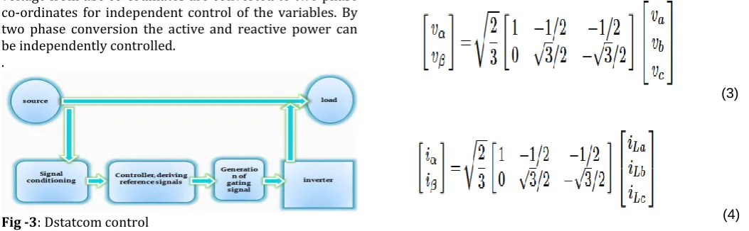
In reference current generation the current and voltage from abc co-ordinates are converted to two phase co-ordinates for independent control of the variables. By two phase conversion the active and reactive power can be independently controlled.
.
Fig -3: Dstatcom control
In this work conventional controllers for reference current generations ie, PQ and SRF control is compared and combination of hysteresis and SPWM current controls for gating pulse generation. Conventional PI controller is used for regulation of the dc link voltage.
3.1 IRP theory
Instantaneous reactive theory was initially proposed by Akagi [8]. It is based on the transformation of three-phase quantities to two phase quantities in α–β frame and the calculation of Instantaneous active and reactive power in this frame [9], [10].
A basic block diagram of this theory is shown in Fig. 3. Sensed inputs va, vb, and vc and iLa, iLb, and iLc are fed to the controller, and these quantities are processed to generate reference current commands (i*sa, i*sb, and i*sc), which are fed to a hysteresis-based pulse width modulated (PWM) signal generation (shown in Fig. 4) to generate final switching signals fed to the DSTATCOM.
The system terminal voltages are given as
va =Vm sin(ωt) vb =Vm sin(ωt − 2π/3)
vc =Vm sin(ωt − 4π/3) (1)
And the respective load currents are given as
iLa =∑ILan sin {n(ωt) − θan} iLb =∑ILbn sin {n(ωt − 2π/3) − θbn}
iLc =∑ILcn sin {n(ωt − 4π/3) − θcn} . (2)
In a–b–c coordinates, a, b, and c axes are fixed on the same Plane, apart from each other by 2π/3. The instantaneous space
Vectors va and iLa are set on the “a” axis, and their amplitude varies in positive and negative directions with time. This is true for the other two phases also. These phasors can be transformed into α–β coordinates using Clark’s transformation as follows
(3)
© 2015, IRJET ISO 9001:2008 Certified Journal Page 2031
Where α and β axes are the orthogonal coordinates.Conventional instantaneous power for three-phase circuit can be defined as
p = Vαiα + Vβiβ (5)
Where p is equal to conventional equation
p = Vaia + Vbib + Vcic. (6)
Similarly, the IRP is defined as
q = Vβiα + Vαiβ. (7)
Therefore, in matrix form, instantaneous real and reactive Powers are given as
(8)
The α–β currents can be obtained as
(9)
Where
Δ = V²α+ V²β (10)
Instantaneous active and reactive powers p and q can be decomposed into an average (dc) and an oscillatory component
. p =p + p
q =q + q (11)
where p and q are the average (dc) part and p and q are the oscillatory (ac) part of these real and reactive instantaneous powers. Reference source currents are calculated to compensate the IRP and the oscillatory component of the instantaneous active power. In this case, the source transmits only the non oscillating component of the active power. Therefore, the reference source currents i*sα and i*sβ in α–β coordinate are expressed as
(12)
These currents can be transformed in a–b–c quantities to find the reference currents in a–b–c coordinates using reverse Clark’s transformation
(13)
Where i*0 is the zero sequence component, which is zero in three-phase three-wire system.
Fig-4: Block diagram of reference current generation using PQ theory
3.2. SRF Method
SRF theory is based on the transformation of currents in synchronously rotating d–q frame [10], [11]. Fig. 5 shows the basic building blocks of this theory. Sensed inputs va, vb, and vc and iLa, iLb, and iLc are fed to the controller. Voltage signals are processed by a phase-locked loop (PLL) to generate unit voltage templates (sine and cosine signals). Current signals are transformed to d–q frame, where these signals are filtered and transformed back to abc frame (isa, isa, and isc), which are fed to a hysteresis-based PWM signal generator [12] to generate final switching signals fed to the DSTATCOM; Similar to the p–q theory, current components in α–β coordinates are generated, and using θ as a transformation angle, these currents are transformed from α–β to d–q frame defined as (Park’s transformation)
(14)
© 2015, IRJET ISO 9001:2008 Certified Journal Page 2032
(15)From these currents, the transformation is made to obtain Three-phase reference source currents in a–b–c coordinate using (13). Reactive power compensation can also be provided by keeping iq component zero for calculating the reference source currents.
Fig-4: Block diagram of reference current generation using SRF theory
3.3. Hysteresis current control
These three-phase reference source currents are fed to the Hysteresis-based PWM current controller to control the source currents to follow the reference source currents in UPF mode of operation.
These currents are considered as the reference source currents iref (i*sa, i*sb, and i*sc), and along with the sensed source currents iact (isa, isb, and isc), these currents are fed to a hysteresis-based PWM current controller to control the source currents to follow these reference currents. Switching signals generated by PWM current controller control the source currents close to the reference current. Switching signals are generated on the following logic, where hb is the hysteresis band around the reference current iref .
Fig-6: Hysteresis PWM current control
1) If (iact) > (iref + hb), the upper switch of the leg is ON, And the lower switch is OFF.
2) If (iact) < (iref − hb), the upper switch of the leg is OFF, And the lower switch is ON.
This current control results in the control of the slow varying source current (as compared to DSTATCOM currents) and therefore requires less computational efforts. Moreover, this scheme automatically compensates the computational delay caused by the processor
3.4. Sinusoidal PWM
In the most straightforward implementation, generation of the desired output voltage is achieved by comparing the desired reference waveform (modulating signal) with a high-frequency triangular ‘carrier’ wave as depicted schematically in Fig.2. Depending on whether the signal voltage is larger or smaller than the carrier waveform, either the positive or negative dc bus voltage is applied at the output. Note that over the period of one triangle wave, the average voltage applied to the load is proportional to the amplitude of the signal (assumed constant) during this period. The resulting chopped square waveform contains a replica of the desired waveform in its low frequency components, with the higher frequency components being at frequencies of a close to the carrier frequency. Notice that the root mean square value of the ac voltage waveform is still equal to the dc bus voltage, and hence the total harmonic distortion is not affected by the PWM process. The harmonic components are merely shifted into the higher frequency range and are automatically filtered due to inductances in the ac system.
© 2015, IRJET ISO 9001:2008 Certified Journal Page 2033
Fig-7: Hysteresis PWM current control3.5 PI Controller for Maintaining Constant DC Bus
Voltage of DSTATCOM
The operation of DSTATCOM system requires ac mains to supply real power needed to the load and some losses (switching losses of devices, losses in reactor, and dielectric losses of dc bus capacitor) in the DSTATCOM. Therefore, the reference source current, used to decide switching of DSTATCOM, has two components: One is the real fundamental frequency component of the load current, which is being extracted using the p–q theory, SRF theory and another component, which corresponds to the losses in DSTATCOM, is estimated using a proportional– integral (PI) controller over the dc bus voltage of the DSTATCOM.
To compute the second component of the reference active current, a reference dc bus voltage (v*dc) is compared with the sensed dc bus voltage (vdc) of DSTATCOM. A comparison of the sensed dc bus voltage to the reference dc bus voltage of VSC results in a voltage error, which, in the nth sampling instant, is expressed as
vdcl(n)=v*dc(n)−vdc(n). (16)
This error signal vdcl(n) is processed in a PI controller, andthe output {Ip(n)} at the nth sampling instant is expressed as
Ip(n) = Ip(n−1) + Kpdc{vdcl(n)− vdcl(n−1)}+ Kidcvdcl(n) (17) Where Kpdc and Kidc are the proportional and integral gains of the PI controller.
The output of this PI controller accounts for the losses in DSTATCOM, and it is considered as the loss component of the current. This component (Ip(n)) can be added with the average real power for controlling DSTATCOM by p–q theory. If the control is facilitated by SRF theory, the output of PI regulator can be added with d-axis component of the current signal.
The fig 8 below shows the compensated system using DSTATCOM connected at the point of common coupling.
Fig-8: Mat lab simulink model of compensated system
4. RESULT AND DISCUSSIONS
The performance of DSTATCOM is studied for PQ and SRF methods of control techniques and current control techniques hysteresis PWM and SPWM and the following observations are made based on these results.
4.1 COMPENSATION OF DSTATCOM USING PQ
AND HYSTERESIS PWM
Fig-9: 1.source current (a) before and (b) after compensation 2. Dc link voltage
© 2015, IRJET ISO 9001:2008 Certified Journal Page 2034
4.1 COMPENSATION OF DSTATCOM USING PQ
AND SPWM
Fig-11: 1.source current (a) before and (b) after compensation 2. Dc link voltage
Fig-12: THD spectrum
4.1 COMPENSATION OF DSTATCOM USING SRF
AND HYSTERESIS PWM
Fig-13: 1.source current (a) before and (b) after compensation 2. Dc link voltage
Fig-14: THD spectrum
4.1 COMPENSATION OF DSTATCOM USING SRF
AND SPWM
Fig-15: 1.source current (a) before and (b) after compensation 2. Dc link voltage
Fig-16: THD spectrum
5. OBSERVATION
Control
THD spectrum
Hysteresis PWM SPWM
Ia Ib Ic Ia Ib Ic
PQ theory 5.148 4.97 5.58 5.78 6.10 5.28
SRF THEORY 4.81 4.7 4.23 4.9 4.9 5.28
Table-1
THD analysis6. CONCLUSION
© 2015, IRJET ISO 9001:2008 Certified Journal Page 2035
ACKNOWLEDGEMENT
I would like to take this opportunity to thank all those who have contributed to this work. I express my heartfelt gratitude to our Director Dr.S.GIyer, Principal Dr.Hariharan.N and the management of Adi Shankara Institute of Engineering and Technology for providing the facilities for the course.
I also thank my guides Asst.Prof Sijo george. They have been a tremendous mentor for me. I would like to thank them for encouraging my research as well as for allowing me to grow as a researcher and for the successful completion of this work.
REFERENCES
[1] Kamal Al Haddad Bhim Singh and Ambrish Chandra.” A review of active filters for power quality improvement.” Industrial Power Electronics, 1990.
[2] J. S. Subjak Jr. and J. S. Mcquilkin. Harmonics-causes, effects,measurements, analysis: An update. IEEE Trans. Ind. Applicat., vol.26, Nov./Dec. 1990pp.1034-1042,.
[3] H. Akagi F. Z. Peng and A. Nabae. “Study of active power filters using quadseries voltage source pwm converters for harmonic compensation.” IEEE Transactions on Power Electronics, vol. 5, no. 1, , Jan. 1990, pp. 9-15.
[4] H.Akagi. “Trends in active power line conditioners“IEEE Transactions on power Electronics, vol 9, no 3, 1994, pp design and implementation for high performance shunt active filters in aircraft power grids”. IEEETrans. Ind. Electron., vol. 59, no. 9, Sep. 2012pp. 3604-3613.
[7] A. Ghosh R. Gupta and A. Joshi. “Performance comparison of vsc based shunt and series compensators used for load voltage control in distribution systems,”vol. 26, no. 1. IEEE Trans. Power Del., Jan. 2011, pp. 268-278.
[8] Y. Kanazawa H. Akagi and A. Nabae. “Instantaneous reactive power compensators comprising switching devices without energy storage components”. IEEE Transactions on Industry Applications, vol. IA-20, no. 3, May/Jun. 1984, pp.625-630.
[9] P. Agarwal S. Jain and H. O. Gupta. “Design simulation and experimental investigations on a shunt active power
filter for harmonics and reactive power compensation”. Electrical Power Components and Systems, vol. 32, no. 7, Jul.2003, pp. 671-692.
[10] IEEE Bhim Singh, Senior Member and Jitendra Solanki. “A comparison of control algorithms for dstatcom”. IEEE transactions on industrial electronics, vol. 56, no. 7, 2009.
[11] B. Singh and S. Arya. “Implementation of single-phase enhanced phase locked loop-based control algorithm for three-phase dstatcom.” IEEE Trans. Power Del., vol. 28, no. 3, Jul. 2013,pp.1516-1524.
[12] Srinivas Bhaskar Karanki Mahesh K. Mishra Senior Member IEEE Nagesh Geddada, Student Member IEEE. “Synchronous reference frame based current controller with spwm switching strategy for dstatcom applications”. 2012 IEEE International Conference on Power Electronics, Drives and Energy Systems,2012.
BIOGRAPHIES
Adarsh.p was born in Kerala, India in 1992. He received the Bachelor of Technology degree in Electrical and Electronics from
College of engineering
Thalassery, Kannur,2013. He is currently pursuing Master of Technology in Power Electronics and Power System at Adi Shankara Institute of Engineering and Technology, Cochin. His current research interests include Power systems, Power quality and renewable systems ,power electronics
Sijo george was born in Kerala, India in 1985. She received the Bachelor of Technology degree in Electrical and Electronics from
Sree Narayana Gurukulam