R E S E A R C H
Open Access
A mobile and portable trusted computing
platform
Surya Nepal
*, John Zic, Dongxi Liu and Julian Jang
Abstract
The mechanism of establishing trust in a computing platform is tightly coupled with the characteristics of a specific machine. This limits the portability and mobility of trust as demanded by many emerging applications that go beyond the organizational boundaries. In order to address this problem, we propose a mobile and portable trusted computing platform in a form of a USB device. First, we describe the design and implementation of the hardware and software architectures of the device. We then demonstrate the capabilities of the proposed device by developing a trusted application.
Keywords:trusted computing, trust, trusted computing platform, trusted platform module, trusted personal device
1. Introduction
The idea of developing and deploying applications that go beyond a single enterprise’s administrative domain has gained popularity in recent times. This has been enabled by recent developments and wide-spread adop-tion of new approaches to software engineering (Web Services and Service Oriented Architecture) [1], the ubi-quity of Internet-based networking and the rapid growth and proliferation of a large variety of mobile computing devices (e.g. laptops, PDAs). As a result, we have seen a growing number of enterprise applications developed to run in heterogeneous, open and potentially hostile envir-onments by accessing enterprise resources remotely [2,3]. Though these applications provide greater flexibil-ity, they present new challenges on establishing a trust between a remote client computer and enterprise appli-cation server, more specifically bootstrapping trust in a hostile environment [4].
Problem statement
An agent, working for a company, is issued a digital cer-tificate (embedded in software or hardware) against which the agent is authenticated. The certificate is used to establish a level of trust between the agent and a company resource (e.g. a server). When the client-server link has been authenticated, customized applications
and confidential client data are available for use by the agent. There are two possible scenarios. The first sce-nario involves the agent using the machine with a preset configuration within the company’s managed network. A digital certificate [5,6], bound to a specific machine along with an attestation mechanism [7] can be used to establish trust in a controlled environment such as this. The second scenario involves the agent working at the customer’s managed network and uses the Internet to establish the trusted transactions with the company’s server. The digital certificate, bound to a specific machine, can be used to establish the trust provided the company presets the machine with the desired config-urations. That is, the agent’s own machine needs to be used. However, a number of issues on mobility and portability of trust arise with this scenario if the agent wants to use any of the client’s machines:
•The certificate is bound to a specific machine thus making it difficult for the agent to work from any other client machine. It would be impossible, for example, to use a client’s machine for accessing information if the agent then tried to use the certifi-cate issued to the agent’s machine on the clients machine.
•When an agent uses the assigned certificate, on an untrusted host machine, the security of the certifi-cate is vulnerable to compromise by malicious soft-ware that may be running on the host machine. * Correspondence: [email protected]
CSIRO ICT Centre, Information Engineering Laboratory, P.O. Box 76, Epping, NSW 1710, Australia
• It is possible for certificate details to be compro-mised in other ways such as theft or loss. One way for a company to alleviate these potential security risks is to periodically revoke old certificates and re-issue new ones. However, this is a complex opera-tion to manage with high overheads and especially so for large numbers of agents operating in the field.
• Downloaded customized applications and confi-dential data are vulnerable to tackle, since this soft-ware operates within an untrusted environment, on the host machine.
This problem has attracted the attention of research communities [8-13]. The trusted computing group (TCG) [8] has proposed a trusted computing platform (TCP) based on the trusted platform module (TPM) [14] cryptographic microcontroller system. The pro-posed platform enables the TPM to be a root of trust for validating both the hardware and software character-istics of the remote computer in which the TPM is installed. In the TCG architectures, a remote client computer can use the remote attestation protocol to attest to its description of characteristics to the enter-prise application server [15,16]. To guarantee the trust-worthiness of the client computer, the description of its characteristics is signed by the TPM. This solution works well in the scenario where enterprises manage all their client computers so that their characteristics are known to them beforehand and can be attested dynami-cally. However, there are two inherent issues with this solution.
•The enterprise systems must have prior knowledge of the characteristics of all their client computers. On the one hand, a single image for all client com-puters may not be a viable solution as different cli-ents may have different requiremcli-ents. On the other hand, the maintenance and management of all client computers with a variety of configurations that meets the requirements of TCG attestation protocol is difficult and challenging.
•The enterprise data and services are now available to a much wider cross section of users, operating under unknown computing environments. In many cases, the users operate beyond a single organiza-tional boundary.
Recently, there has been a growing interest in addres-sing this problem from industries. A number of USB-based solutions have been developed such as IronKey [9], DIVA [17], EnCryptakey [10] and Gemalto [18]. Although all these solutions are designed to address above two issues, none of them use the emerging TCP proposed by TCG. Therefore, they miss all the benefits
that come with the TCG’s trusted computing technolo-gies such as memory curtaining and protected execu-tion, sealed storage, remote attestaexecu-tion, and integrity measurement, logging and reporting [19]. Motivated with this scenario, this paper proposes a novel solution based on TCG architectures. The proposed solution provides a TCP on a USB device so that it enables the mobility and portability of trust for enterprise applica-tions. To the best of our knowledge, this is the first attempt to provide a TCP in the form of a USB device. Our proposed solution addresses two issues discussed earlier as follows. The TCP in a USB device (dubbed as
TCP in your pocket) addresses the first issue as
enter-prises can issue such devices with known description of their characteristics. The second issue is also addressed as the device can be plugged into a USB port of any unknown computer and create a known TCP whose execution environment is isolated from the host computer.
The rest of the paper is structured as follows. We pro-vide a motivation for our proposal through a survey of related work in Section 2. Sections 3 and 4 provide a review on two important aspects of TCP used in our solution: the TPM and the TCG remote attestation pro-tocol. In Section 5, we describe a design and implemen-tation of the hardware architecture for the proposed device. This is followed by the presentation of a software architecture and its implementation in Section 6. Sec-tion 7 describes an implemented prototype demonstra-tor for a financial application. We then present the security and performance analysis of the proposed solu-tion in Secsolu-tion 8. The final secsolu-tion draws the conclusion and outlines the possible future works.
2. Motivation and related work
The aim of this section is to provide a motivation for the proposed USB-based TCP through a review of related work. The issue of portability and mobility of trust is not new. A variety of trusted personal devices (TPD) have been developed, whose physical form factor ranges from smart cards to USB-based devices. A detailed survey on the evolution of TPD can be found in [20]. We first provide an overview on the TPDs and then review only relevant USB-based devices and their applications in the context of this article.
malicious behavior such as identity theft and fraud. However, smart cards use a different protocol from the ones computers use to communicate with each other over a network. Because of these protocol differences, a smart card when connected to a computer cannot talk directly to a remote machine using the network proto-cols. The computer must use middleware to do protocol translation so that the two protocols (i.e. card/computer and computer/network) can understand each other.
This arrangement is required for example if a smart card needs to communicate with a remote server on the Internet; middleware is required either on the host com-puter or on both the host machine and a remote server. Furthermore, a smart card needs a card reader and asso-ciated drivers in order to connect with a computer, but unfortunately most computers do not have built-in card readers. Therefore, implementing a smart card solution requires a supporting infrastructure including card reader, device drivers and middleware for protocol translation. These technical constraints provided the sti-mulus for research into a new generation of smart card known as the Network Smart Card [22-25] or USB smart cards [26,27], which talks directly to a remote ser-vice provider via a host machine’s Internet connection; i. e. sessions are handled by the network smart card itself with the host machine providing a network bridge to the remote server.
The justification for network smart cards, as outlined above, is clear. However, in the face of the increasing number of security and privacy threats leveled at the smart card space, due to the lucrative potential afforded by fraud, identify theft and all that this entails, a smart card must also embody trust technology if it is to be truly considered a TPD. This implies that the depen-dency of smart cards on the perceived trustworthiness of public host machines, to which they interface, should
be eliminated and that security, based only on crypto-graphy and SSL/TLS technology, needs to be augmented with trust technologies and protocols. In addition, the security solutions based on USB smart card [26-28] still need some software (i.e. Host Agent) to run in the host machines to proxy the communication between the smart cards and the remote servers. On the one hand, if the host is untrusted, it is hard to guarantee the integ-rity of such proxy software. On the other hand, if the smart card is not trusted by the host owners, the proxy software might not be allowed to run.
To satisfy these requirements, an alternative breed of TPD is emerging that specifically addresses the problem of creating a trusted environment on an untrusted host using a combination of a TPM to establish a root-of-trust and virtualization technology supporting virtual machines that can provide well supported, strong isola-tion between applicaisola-tions. As network smart cards and this emerging breed of TPD evolve, utilizing similar technologies and form factors (e.g. USB token), the technical distinction between them will become increas-ingly blurred. As such the dominant distinguishing fac-tor between these two classes of device will no doubt be the application scenarios of use. We next focus on the emerging breed of TPD relevant to our paper.
As part of its Securing the Intelligent Nationinitiative, the Singaporean government has introduced a standar-dized nationwide security smart token called Digital Online Registration and Identification System (DORIS) [29]. This token offers all Singaporean companies and citizens certified, secure access to government services. DORIS is implemented as a specialized USB thumb-drive hardware token. The core of DORIS is a secure microcontroller, flash memory, and a small radio trans-ceiver and antenna used for electronic ID and online/ offline authentication.
Trusted Personal Devices
Smart Cards
Network Smart Card communication via Internet Protocol stack
PKI infrastructure Traditional Smart Card
communication via dedicated reader PKI infrastructure
Emerging breed of TPD
Establish trust at boot Establish trust at run time
DORIS suffers from a portability and mobility problem as it requires an installation of a specific driver. To address this problem, a software version of the device was developed, calledDynamic Isolation of Virtualized
Applications(DIVA) [17]. When DIVA is plugged into a
PC, it creates an isolated command window which acts as a user’s own trusted software execution space to pro-vide secure access to a wide variety of applications. Furthermore, the user interacts with the virtual applica-tion via a Virtual Keyboard to mitigate the risk of key stroke logging attacks. One of the limitations of DIVA is that it can only be used on the Windows platform, as it was built specifically for that environment. Furthermore, DIVA is a pure software-based solution as compared to its predecessor DORIS. We have also developed a simi-lar prototype system based on TCG specification, called Trust Extension Device (TED) [30]. It uses the type II virtual machine and emulated TPM. Though it provides a seamless portability and mobility, it cannot provide the isolated execution space due to the inherent limita-tions of type II virtual machine.
In addition to the government services, the need of a mobile and portable trusted environment is realized in other application domains including enterprise applica-tions. In recent times, a number of commercial products have emerged for enterprise applications. Encryptakey is a small portable (USB form factor) device that allows mobile users to create a seamless and secure environ-ment in which one can perform digital transactions, surf the Web, conduct business and communicate securely and privately [10]. Encryptakey is a biometrically authenticated device which offers multiple-levels of authentication and comprises its own micro chip, mem-ory, RFID capability and Bluetooth interface. Encrypta-key, when plugged into a local computer, unloads the native operating system of the host machine and down-loads its own operating system (OS) which it works with exclusively. In doing so Encryptakey is shielded from any form of malware (e.g. viruses, key-loggers, screen-scrapers) that may reside on the OS of the host machine. Encryptakey embodies the same principle of isolation for creating a trusted environment on a host machine similar to DORIS/DIVA. However, one signifi-cant difference is that Encryptakey must unload the native operating system to install its own OS. This fea-ture does not meet the seamless mobility and portability requirements.
There are other competing industry products from IronKey [9] and Gemalto [18]. All these products aim to provide a mobility and portability of trust for a variety of applications ranging from the secure surfing of the Web to the secure access to enterprise data. The Iron-Key uses AES hardware encryption technology and works with most platforms without the need to install
or modify any software, including the host’s operating system. Gemalto’s Smart Guardian [18] is similar to Ironkey in many aspects. A comprehensive comparison of these products is difficult to achieve due to the una-vailability of the technical papers related to them.
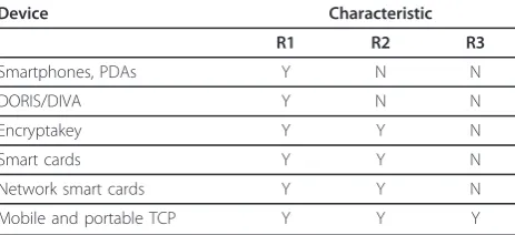
Although a comprehensive comparison is difficult, a comparison of high level characteristics is possible. Referring to the definitions of trustedand trustworthy
systems in [31], we may characterize trustworthy devices according to the following high level features:
R1It may be unambiguously identified. That is, it has a secure, known, verifiable identity.
R2The device operates unhindered. Its operation cannot be manipulated so as to behave in an unex-pected manner.
R3The device can attest its consistent good beha-vior, either directly with an interacting entity, or indirectly, through a trusted third party.
Table 1 shows a comparison of TPDs based on the above described features. It is clear from the table that USB-based TCP has a unique feature of attestation sup-ported by underlying trusted computing technologies. Summarizing, the growing number of USB-based trust devices in the market place clearly shows the need, value and significance of such devices. They are in demand for a variety of applications from secure surfing of the Web to secure access to government services. To the best of our knowledge, none of these devices have been developed utilizing both the TCG specification and dedicated hardware TPM chip, as shown in Table 1. Hence, they miss the benefits of having TCG’s trusted computing technologies such as memory curtaining and protected execution, sealed storage, remote attestation, and integrity measurement, logging and reporting. Thus, the paper proposes a USB-based TCP that is compliant with the TCG specification, and demonstrates the feasi-bility of such device by developing an engineering proto-type utilizing a dedicated hardware TPM chip. A recent report [32] analyzes that, to promote the acceptance of TPM security functionalities, it is desirable to develop
Table 1 Trusted personal device comparison
Device Characteristic
R1 R2 R3
Smartphones, PDAs Y N N
DORIS/DIVA Y N N
Encryptakey Y Y N
Smart cards Y Y N
Network smart cards Y Y N
useful end-to-end security capabilities that can be used by end users without additional software development. The TCP proposed in our paper is providing such TPM-based security capabilities to end users.
3. Trusted platform module
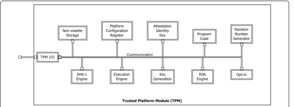
This section provides a brief review on TPM and its functionality. The TPM is a cryptographic microcon-troller specified by the TCG. Figure 2 shows a TCG TPM architecture. The TPM provides a hardware-based root of trust, and contains cryptographic func-tionality to generate, store, and manage cryptographic keys in hardware. One of the aims of the TPM is to provide a cost effective way of “hardening” of many of today’s commonly deployed applications that pre-viously relied solely upon software encryption algo-rithms with keys kept on a host’s disk. Another aim is for the TPM to provide proof of the integrity of plat-form through measurement of the platplat-form’s operating environment (hardware, device drivers, operating sys-tem, and applications) and attestation of these against a well-known and carefully defined and maintained set of characteristics.
As shown in the figure, a TPM includes a Random
Number Generator (RNG). The RNG is used in the
creation of RSA key pairs that are internal to the TPM. At the time of manufacture, a cryptographic key pair, known as the Endorsement Key(EK), is generated and stored inside the TPM chip. The private part of the EK is held securely by the chip, and is never exposed. Another important concept in TPM is theroot of trust. The source of the root of trust is the Storage Root Key
(SRK). The SRK is the first key pair generated by the TPM which is never exported from the TPM. Each sub-sequent RSA key pair that the TPM generated is bound to this original SRK.
The private keys are either securely stored in the TPM. If they need to be stored on a disk, they are encrypted and exported from the TPM. The encrypted key can only be securely decrypted internally on the TPM. This means unencrypted keys are never stored or visible outside the TPM. The TCG standard version 1.1b [14] specifies that TPM performs the following functions:
•Key generation: public key functions for key pair generation using a hardware RNG;
•Cryptography and secure storage: public key signa-ture, encryption, and decryption to enable secure storage of data and digital secrets;
• Integrity measurement: storage of hashes that enable verifiable attestation of the machine config-uration when booted;
•Unique identity: an EK that can be used to anon-ymously establish that an identity key was generated in a TPM; and
•Ownership: initialization and management func-tions that allow the owner to turn TPM functionality on and off, reset the chip, and take ownership of its functions.
The TPM’s RNG generates the seed numbers for the cryptographic processor’s encryption, decryption, and key generation functions. The TPM’s non-volatile memory securely stores encryption keys, including the SRK, EK, and other sensitive data. The TPM employs conventional cryptographic operations in conventional ways. The opera-tions supported by TPM include asymmetric key genera-tion (RSA), asymmetric encrypgenera-tion/decrypgenera-tion (RSA) Hashing (SHA-1) and RNG. The TPM uses these capabil-ities to perform generation of random data, generation of asymmetric keys, signing and confidentiality of stored
Trusted Platform Module (TPM) TPM I/O
Non-volatile Storage
Platform Configuration
Register
Attestation Identity
Key Program
Code
Random Number Generator
SHA-1 Engine
Key Generation
RSA
Engine Opt-in
Execution Engine
Communication
data. The TPM may use symmetric encryption for internal TPM use but does not expose any symmetric algorithm functions to general users of the TPM. The Key Genera-tion component (Figure 2), creates RSA key pairs and symmetric keys. The SHA-1 hash capability is primarily used by the TPM to support measurement taking during platform boot phases and to allow environments that have limited capabilities access to a hash functions. The Opt-In component provides mechanisms and protections to allow the TPM to be turned on/off, enabled/disabled, activated/ deactivated. The execution engine runs program code to execute the TPM commands received from the I/O port. Non-volatile memory component is used to store persis-tent identity and state associated with the TPM. This area has set items like the EK.
A platform configuration register (PCR) is a 160-bit storage location for discrete integrity measurements. There are a minimum of 16 PCR registers. All PCR reg-isters are shielded locations within the TPM chip. The decision of whether a PCR contains a standard measure-ment or if the PCR is available for general use is deferred to the platform specific specification. An Attes-tation Identity Key (AIK) is an alias for the EK. The EK cannot perform signatures for security reasons and due to privacy concerns. TPMs contain secure non-volatile storage space that is intended to contain measurements of system hardware and software status. Measurement consists primarily of submitting all system software and hardware to a hash algorithm in a predetermined sequence. If this measurement is performed when the system is in a known trusted state, then the resulting hash can be stored in the TPM and compared to the result of a subsequent measurement. Any changes will be detected by the comparison, and appropriate actions can be taken to prevent execution of modified software or hardware. This measurement capability can be used to provide detection of any remote system modifications resulting from malicious viruses or worms.
The purpose of TPM is to provide hardware-based digital certificates for establishing trust since software-based solutions are vulnerable to malicious attacks. TPM is gaining acceptance by the computing community as a technology for establishing trust between entities (e.g. cli-ent-server). Essentially, TPM validation attests to the trustworthiness of bonafide versions of software and hardware products operating on a platform.
Summarizing, the purpose of the TPM in the portable device is to establish a trust relationship between client-server entities where the goals of trust are to ascertain that:
• The TPM is the genuine owner of certain crypto-graphic keys and certificates, i.e. the TPM has not been tampered with.
•The software operating within the (created) trusted environment is genuine; which includes validating secure applications and the operating environment.
•If a device is lost or stolen, then the issuer of the TPM revokes the manufacturers TPM credentials, thereby disabling the device from engaging in further transactions.
4. Remote attestation
Attestation is the process of reporting the measured
platform’s integrity values, and proving that the platform has a genuine TPM at the same time [33]. The attesta-tion protocol in version 1.1 of the TCG specificaattesta-tion [14] introduces the concept of a trusted third party, the
Privacy Certifying Authority, or Privacy CA. The Privacy
CA is known and trusted by both the client and applica-tion service provider. On the other hand, the client (at least initially) does not trust the service provider, and v.v. Because of this trust relationship (i.e. client trusts the Privacy CA; client does not trust the service provi-der) the client will send its credentials to the Privacy CA, it will not send it to the service provider directly. As such, any identity claims made by the client will be verified by the Privacy CA.
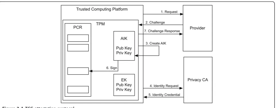
We now move onto an explanation of the TCG remote attestation protocol through an elaboration of the steps in Figure 3.
1) A client with a TCG platform requests a service from a service provider (e.g. for access to a confiden-tial data information).
2) The service provider’s machine (also with a TPM) challenges the client’s platform with an attestation request.
3) Upon reception of this request, the client plat-form generates an AIK using the TPM function
CollateIdentityRequest.
4) The platform then assembles all the embedded credentials of its TPM together with the new AIK, signs the whole with the TPM private EK, and encrypts it all with the public key of the Privacy CA. This information forms the identity request. It is important to note here that the EK cannot be used to sign arbitrary data, only by some internal func-tions such as TPM.CollateIdentityRequest. This means that the owner of a TPM cannot generate a falsified identity request, and signs it with the EK. This request is then sent to the Privacy CA.
it can be sure that the request is issued from the TPM which possesses this particular EK. The privacy CA will now generate a certificate (called Identity Credential) containing the public part of the AIK, signed with its private key, to attest that the TPM is genuine. This certificate is encrypted with the public part of the EK of the service consumer. This certifi-cate is called an Identity Credential. The Identity Cre-dential is then sent to the service requester/consumer (that has TCG platform).
6) The platform then prepares an attestation mes-sage which includes signed PCR values and identity credentials. The signed value is generated using a specific function TPM.Quote and the credential is retrieved using a function TPM.ActivateIdentity. This means the platform cannot generate fake attes-tation message. The message is then sent as a response to the application server.
Several problems have been identified related to this protocol, and are being examined and addressed in cur-rent efforts within the TCG and elsewhere. These pro-blems are related to the difficulty in measuring a platform configuration accurately, and comparing it against a well-known and standard configuration. In today’s complex systems, composed of large numbers of interconnected heterogenous computing environments, performing an integrity measurement is almost mean-ingless unless there is very strict control on the hard-ware, operating systems and applications. These problems are driving further research activities in remote attestation, and well-known examples include Direct Anonymous Attestation [34], Semantic Remote Attestation [35], Property-based Attestation [36], and Fine Grained Attestation [37].
BIND, for example, uses a technique that attests only the critical code immediately before it executes. A sand-boxing mechanism similar to Secure Kernel found in AMD’s Secure Execution Mode (SEM) [38] to protect the execution of the attested code. It can detect the changes of attested code at runtime caused by buffer overflows or string malformation. Another approach was taken by Terra [39]. Terra attests the Trusted Vir-tual Machine Monitor (TVMM) which then is used to partition the platform into multiple isolated Virtual Machines. Here, because the TVMM is so small and uniform, the attestation can proceed easily and in a manageable manner.
The TCG remote attestation protocol is designed to establish one-way trust relationship. We refer to this protocol as amessage-based attestation protocol, as it was designed to be run for each message exchanged between the end hosts. We make the following observa-tions, based on our experiences in using the protocol in our system. First, it is inefficient, as the number of pro-tocol (overhead) messages per application message is high (of the order of eight pairs of protocol messages per application message). Second, the difference in the time at which the attestation is completed and the time at which it is used to send the application message makes it vulnerable to attack. To overcome these short-comings in this application scenario, we propose a
ses-sion based mutual attestation protocol[40]. Yoshiham et
al. [41] present a similar proposal calledWS Attestation, where they presented an attestation architecture that can be used in Web Services environment.
We now move onto the design and development of mobile and portable TCP utilizing the concepts outlined in the above two sections (namely, the use of the TPM, and remote attestation, in trust establishment).
TPM
Trusted Computing Platform
Provider
Privacy CA PCR
AIK
Pub Key Priv Key
EK Pub Key Priv Key
1. Request
2. Challenge
4. Identity Request
5. Identity Credential 7. Challenge Response
3. Create AIK
6. Sign
5. Design and implementation of hardware architecture
This section first draws the design requirements for a USB-based TCP based on the discussion in Section 2, then presents a reference hardware architecture and closes with an implementation of the proposed device.
We start with the following high-level design require-ments for the device.
Dimensions
The device dimensions should be small and portable, preferably USB thumb drive size. It was decided that the dimensions (width, length and thickness or height) of 18 mm × 58 mm × 10 mm would be ideal.
Cost
The device must be cheap enough to be disposable if it has been compromised or lost. The device is meant to be issued to a select set of its clients, but still controlled and managed by an issuing enterprise.
Physical connection
The device connects to any host PC using a USB 2.0 compliant type A plug.
Electrical requirements
The device uses the host computer’s USB port for power, supplying 4 USB units of current (400 mA) at the nominal USB VBUS voltage (5 Vdc).
Internet connectivity
The device establishes Internet network connectivity via the USB port. Internet connection to remote servers must be secured using 128-bit SSL or better.
No host interference
The host computer needs to keep operating uninter-rupted when the device is inserted and booted. This is unlike some other trusted platforms that require the host to be shut down before trusted device was inserted into the USB port and then rebooted from the USB attached device.
Device insertion and removal robustness
The device may be inserted and removed at any time (including device boot, mid-transaction, or conclusion of transaction session) without adversely affecting either the host PC, or the device itself.
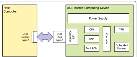
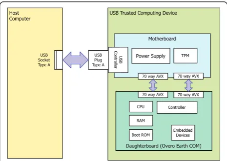
As per the above requirements, Figure 4 shows our high-level reference design of a USB-based TCP con-taining a TCG TPM. The most notable difference between our reference platform to that of TCG PC reference platform [8] is that (1) the device does not
have any user input or output devices such as a display or keyboard and (2) there is only a single physical net-work interface to the device, namely the USB port.
Our goal was to achieve a hardware implementation that stays as close as possible to the reference platform shown in Figure 4. Our aim was to show the feasibility of the idea through the development of a concept demonstrator. Given the time to develop, integrate and test the hardware and software systems, it was decided very early in the project to base the implementation on an existing embedded hardware platform. We investi-gated various embedded systems using the following cri-teria: good support for a version of the Linux operating system; development tools that allow easy development; a USB form factor and a significant community of users and developers. These criteria lead us to the select of the Gumstix Overo Earth Computer-on-Module (COM) [42]. The development kit associated with this product features a motherboard that carries the Gumstix Overo Earth COM as a daughterboard, and offers a rich variety of interfaces: a USB OTG port, two mini USB serial (terminal) ports, control and status ports and some forty general purpose input/output ports that can used for a variety of uses, including interfacing to the TPM chip and providing clock and data input and output.
Using this development kit allowed us to quickly pro-totype a secondary “TPM only” board that connected to the development kit motherboard, and allowed the soft-ware development to progress without waiting for the final design and implementation of a small, USB form-factor motherboard.
Figure 5 shows the implementation hardware architec-ture for the proposed device. As mentioned above, the device replaced the development kit and attached sec-ondary prototype “TPM only” boards with a single, USB-form factor motherboard, that connects the Gum-stix Overo Earth COM via two 70-way low profile AVX connectors. The motherboard carries the TPM chip, clock generation, voltage regulators and logic level con-version (to allow interfacing between 1.8, 3.3 and 5 V logic levels) circuitry, a USB plug with input protection circuitry and two low profile 70 pin EVX sockets.
Host
Computer USB Trusted Computing Device
USB Plug Type A
USB
Contr
oller
Power Supply
Contr
oller
RAM Boot ROM
CPU TPM
Embedded Devices
USB Socket Type A
Figure 6 shows the completed hardware device, as viewed from the component side of the motherboard. Given that the implemented device has no (usual) user interface, the motherboard design included two status information LEDs, one indicating that the system has power, and the other that the device has successfully booted.
The motherboard components are divided into two major subsystems: the TPM subsystem and power sup-ply subsystem.
The TPM subsystem consists of the TPM chip itself, logic level shift circuitry to interface the TPM chip’s 3.3 V logic to the Overo Earth COM 1.8 V logic, a TPM reset circuit and a timing oscillator for the TPM chip.
The selection and sourcing of the TPM chip was somewhat unusual, as the system implementation was on a commercial embedded computer, rather than a general purpose PC. This meant that there were restric-tions on the type of TPM chip that could be used. Most of the widely available TPM chips are meant to be inte-grated into a general purpose PC (whether it be laptop or desktop), and connected via the PC’s own internal LPC bus [43]. Unfortunately, commercially embedded
computers do not use this bus to interconnect the var-ious devices found on an embedded computing plat-form. They do however offer a large number of serial (GPIO) [44] interfaces and that in turn meant that the design had to rely on a serial bus version of a TPM chip–the Atmel AT97SC3203S0-X9A20.
One of the most critical design factors was that the device must meet the stringent insertion and removal robustness requirement. The device was meant to be plugged into and unplugged from the USB 2.0 ports on a variety of computers without causing unexpected behaviors in either of the device or the host computer. There are many factors that need to be considered in the design: the speed and method at which the device insertion occurs; the reliability and cleanliness of the physical contacts; the ability of the host computer to supply“clean” USB 2.0 power at the required 400 mA at 5 Vdc; whether the removal of the device is during a particularly critical part of the device boot process; whether the removal of the device occurred during a critical transaction and so on.
Irrespective, under all insertion and removal events, the device hardware and software was not permitted to enter into an unexpected state, and could not cause interruptions to the host computer.
The approach taken in the final design and its imple-mentation was to ensure that allpower supply transi-ents caused by the physical insertion (and removal) had decayed to sufficient levels so that the power supply subsystem regulators were presented with as clean a vol-tage/current supply as possible. It was only after the transients had decayed, and the regulators finally were operating at nominal capacity that the power supply subsystem could then switch itself into supplying power to the Overo Earth COM and to the TPM subsystem.
We noted that there are two classes of transients of concern to this type of device. First, is the short lived, high voltage, high current electrostatic discharges to the device. The second type is much longer lived transient, where the power being supplied is extremely noisy due to the physical insertion of the device into the USB port. In this case, both the voltage and current supplied is highly unpredictable until reliable physical contact is finally established.
Our power supply subsystem design overcame these two types of transients by providing two levels of pro-tection as outlined below. The power supply subsystem consists of USB port electrostatic discharge protection circuitry, a power sequencing circuit, and three separate voltage regulators. The combination of the USB port protection circuitry and power sequencing circuits elimi-nated both the short electrostatically induced transient currents and the longer duration, multiple voltage tran-sients that occur when the device is first physically
USB Trusted Computing Device
Motherboard
Daughterboard (Overo Earth COM) Host
Computer
USB Plug Type A
USB
Contr
oller Power Supply
Controller
RAM
Boot ROM CPU
TPM
Embedded Devices USB
Socket Type A
70 way AVX 70 way AVX
70 way AVX 70 way AVX
Figure 5 An implementation architecture of USB trusted platform computing device.
connected to the host computer. These two protection circuits assured that each of the three regulators and subsequent connected components (including the Overo Earth COM and TPM chip) had “clean”power supplies when the device is first connected into the host compu-ter, allowing the entire device to enter a stable, repeata-ble boot sequence.
The first of the regulators supplies a 1.8-V reference voltage level to the logic level translation between the Overo Earth COM and the TPM chip. As it supplies only a reference level, the power requirements were small and so a Torex linear low-dropout regulator (LDO) XC6204 in a SOT-25 package was selected. The second and third regulators both supply 3.3 V. The first of the 3.3-V regulators, a Torex XC6203 (again, linear LDO) in a SOT-89 package supplied power (3.3 V at 55 mA) to the TPM chip on the motherboard. The second, much larger capacity 3.3 V regulator supplied 250 mA required by the Overo Earth COM daughterboard. Because of the demanding power requirements, a Linear Technology LTC3405 switch mode (synchronous step) regulator was selected in a S6 package. This device is able to supply up to 300 mA at 3.3 V to the Overo Earth COM. The decision to use two separate 3.3 V reg-ulators rather than a single regulator was based on con-sidering the power requirements and the dimensional constraints of the prototype device. Choosing a larger single regulator (in place of the current two) was prohi-bitive due to the height restrictions placed on the device dimensions (including the housing). The larger single regulator package (that was able to supply power to both the TPM and Overo Earth COM) was outside of the maximum height requirements specified, although the package footprint presented on the printed circuit board was similar to the LTC3405.
A total of six prototype devices were produced and tested. Each of the prototype devices underwent thor-ough and rigorous testing scheme that examined maxi-mum power usage, noise sensitivity, multiple insertion and removal events at random times, long term power consumption and device functionality, and a variety of operational tests. All six prototypes have been used and successfully demonstrated in a variety of applications and situations. These include two live demonstrations at international conferences and three days at CeBIT Aus-tralia, where two of the devices were plugged and unplugged at random times during the three days of the public exhibition, and always operated correctly.
Once again, we believe that the careful attention to the demands of having a stable power supply in a highly dynamic and unpredictable environment, where the device can be plugged and unplugged into any host USB port resulted in the hardware devices’ ultimate “good behavior”.
6. Design and implementation of software architecture
Our platform is a portable embedded device and needs to support both native and external applications. While designing the software architecture, we made some stra-tegic decisions to ensure that efficiency, access by a vari-ety of applications, and portability were not compromised in any way. Figure 7 shows the software architecture of our platform, with the components described in the fol-lowing section. Underpinning the system software is the embedded operating system, based on an optimized Linux kernel (v 2.6.29) which includes USB, I2C and TPM device drivers. All compilation and configuration of the kernel is done through the OpenEmbedded (OE) development environment. As mentioned, the prototype has a specially reduced, customized kernel so as to improve its power efficiency, responsiveness and boot up speed.
The USB driver allows the platform to appear to cli-ents as an IP network device. We have used the popular Linux USB Ethernet/RNDIS gadget driver in the kernel module. Adopting this approach meant that the plat-form can be easily connected to most operating systems such as Ubuntu Linux, Apple Mac OS × and Windows. This module establishes a Remote Network Device Interface Specification (RNDIS) link between the plat-form and the client, upon which TCP/IP is used. The platform runs a lightweight DHCP server, which dyna-mically assigns an IP address to the host. Through this IP link, the USB based trusted device can communicate with other machines on the network.
The TPM chip is connected to the embedded CPU via the I2C bus. The I2C device driver and TPM driver is used by the TPM library to access the TPM chip. The I2C driver makes the TPM chip appear as a device file in Linux, and the TPM driver maintains the I/O state of the device file. The TPM driver provides operations
tpmSend andtpmReceiveto send and receive data from
the TPM chip. If the device file is closed, the TPM dri-ver initializes the device, and then opens the device file,
Embedded CPU External
Applications
TSS Server ApplicationsNative
Lightweight TSS Library
Embedded Operating System TPM Driver
I2C Driver
USB Extension TPM
Extension
USB Driver
which is then ready to be read and written. The TPM driver can also output the raw bytes to and from the TPM chip for facilitating debugging.
The TPM library provides the operations to handle TPM commands. The main operation takes as the input a command name and the command parameters, returning the result received from the underlying TPM chip. The TPM library also provides an interface file, which explicitly describes the parameter and output structures for each command. For example, the inputs for the command TPM.Sign includes a key handle for the signing key, the usage authorization for the key, the data to be signed and its size, and the output of this command includes the signed data and its size.
To process the TPM commands efficiently, we made the following two-design decisions. First, we adopted a template-based TPM command construction. The TPM library prepares a command template for each TPM command in the runtime stack. When issuing a TPM command, it replaces the template with the correspond-ing parameters without allocatcorrespond-ing new memory in the heap. Second, we only implemented a subset of TPM commands that are suitable for a portable trusted plat-form. For example, our TPM library does not create migratable keys when using the command
TPM.Create-WrapKeysince the device is already a portable device.
One important and particularly difficult part of hand-ling TPM commands is to generate correct input and output authorization. With incorrect authorization, the commands cannot be executed by the TPM chip nor the output be correctly accepted. It should be noted that some TPM commands do not need authorization, while others may need one or two authorization han-dles. The TPM library provides several operations which can automatically generate or check authorization bytes, hence making it easier to deal with TPM command authorization. Using these operations greatly improve the correctness of command authorization and the development efficiency.
At the top of the supporting software architecture is the Trusted Software Stack (TSS) library and the TSS server. The TSS is a specification defined by TCG [45], describing the TPM commands and other cryptographic operations for the application developer. We have designed a lightweight TSS library as the portable device may not need a library similar to a general-purpose device such as PC. The main operation in our TSS library is to support remote attestation. This operation involves the TPM commandsTPM.MakeIdentity for creating an AIK, and TPM.ActivateIdentityKey for activating the identity certificate receiving from the Privacy CA.
The portable trusted device needs to support two types of applications: native and external. We refer applications that run within the operating environment
of portable trusted device and need to be measured for attestation purpose to as native applications. The appli-cations that run outside the portable trusted device, but use the TPM in the portable trusted device are referred to as external applications. For example, an enterprise Web-based applications may use portable trusted device for authentication purpose. We have defined TSS server to support such external applications.
The TSS server is a daemon that allows external Web applications to access the platform’s TPM functional-ities. The TSS server provides TPM functionality to Web-based applications by embedding the commands in HTTP, while device local applications are able to directly access the TSS library as designed by the cur-rent TCG specification.
For example, when an application wants make a TPM AIK, it posts a HTTP request with the parameter
tedcmd taking the value assigned to the operation of
making AIKs. We demonstrate the use of this architec-ture by developing a Web application in the next section.
7. Design and implementation of application scenario
Figure 8 presents a high-level enterprise architecture showing how a USB-based TCP is meant to be used, and the components that are required to support it. There are three components involved in running an application based on the USB-based TCP. In a typical use scenario, a USB-based TCP is plugged into an unknown host computer. Depending on the application selected, the host computer may also be used to allow the user access to a variety of Input/Output interfaces such as a screen display and keyboard/mouse. Note that they are not a part of the USB-based TCP reference platform as shown in Figure 4. The Privacy CA validates a USB-based TCP’s characteristics to a remote party by running a TCG attestation protocol. This means all
USB-based Trusted Computing
Platform
Host Machine
Privacy CA
Application Server
devices’ characteristics are known to the Privacy CA. The application server hosts an application that USB-based TCP uses to process any critical transaction.
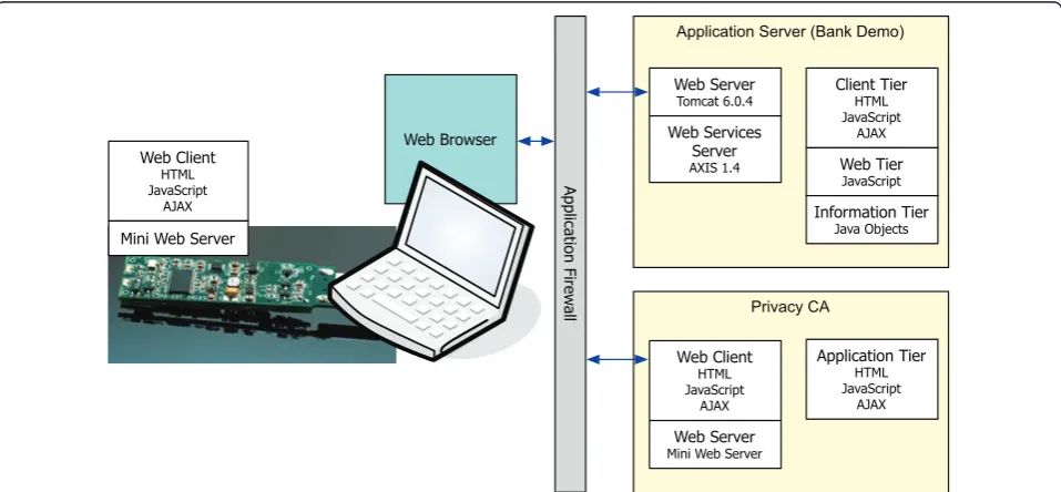
Based on the above enterprise architecture, we have developed a small demonstration application that exer-cises most of our USB-based TCP’s capabilities. Our demonstrator uses a familiar banking transaction sce-nario which allows a customer to view account balances and transfer money from one account to another after successful authentication took place. The layouts and technologies used in our demonstrator are shown in Figure 9.
Our USB-based TCP contains a mini Web server, developed in-house, that contains sufficient functionality to process SOAP formatted HTTP request/response messages. Similarly, we also have another mini Web ser-ver running on the Privacy CA component. These mini Web servers enable us to conduct driverless communi-cation among the components in our enterprise archi-tecture using standard Web languages such as HTML, JavaScript, and AJAX. The application server hosts our banking demonstration written in JSP. The Apache Tomcat Server and Apache Axis engine are also installed in our application server to support Web-based services. Java Objects are used in the application server to provide database functionality to allow us to store the banking information for each customer. We developed our own in-house Privacy CA as a standalone Java application.
When the device is plugged into the host machine, it allocates a link local IP address to it, used for
communication between the local host and the device. When a user types a URL to access services from the application server, the host machine becomes aware of the IP address of the application server. However, the USB device and application server are unaware of each other’s IP address as the current addresses are local. We solved this issue by designing a Web page with embedded JavaScript code that performs as an address proxy. We next describe the design and implementation of the Web page in the context of the attestation proto-col, and include some code snippets to illustrate the important points.
Figure 10 illustrates the overall Web page compo-nents. A JavaScript-based proxy is embedded in the main page. The proxy is basically a listener that watches for any incoming or outgoing messages. The main page itself contains two iframe tags. Each iframe uploads HTML files that are located on the portable device and the Privacy CA. These files are loaded when the main page is rendered by the client browser. Once loaded, the JavaScript proxy code associated with the main page starts executing, allowing communication by both the device and Privacy CA to the application server.
The mobile and trusted platform operating within this scenario operates as follows.
1) A customer plugs in the TCP device into the USB port on an untrusted host PC. When the device is plugged in, it draws power from the host PC and boots its operating system. It then loads libraries and applications as shown in Figure 7.
Privacy CA
Application Server (Bank Demo)
Web Client
HTML JavaScript
AJAX
Mini Web Server
Web Browser
Application Fir
ew
all
Web Server
Tomcat 6.0.4
Web Services Server
AXIS 1.4
Client Tier
HTML JavaScript
AJAX
Web Tier
JavaScript
Information Tier
Java Objects
Web Server
Mini Web Server
Application Tier
HTML JavaScript
AJAX
Web Client
HTML JavaScript
AJAX
2) The customer uses a known, secured browser to access the bank’s application through a URL. The main page contains two iframes as follows.
<iframe src=<%=pcaURL%>
/privacyCA.htm id="caFrame"/> <iframe src=<%=tedURL%>
/ted.htm id="tedFrame"/>
The first iframe is designed for privacy CA and the second for the TCP device.
3) When the main page is rendered, two HTML pages, privacyCA.htm and ted.htm, are uploaded connecting the application server to the device and privacy CA. The user then performs a simple name/ password authentication with the application server via HTTP message to the application server as a part of a login request.
4) If the customer authentication based on user-name/password succeeds, a challenge message is issued by the application server containing a random nonce. Thus communication is handled by the fol-lowing JavaScript fragment:
function sendChallenge (nonce) { var win = document.getElementById
("tedFrame”). contentWindow;
win.postMessage
(nonce,+ < % = tedURL% > +); }
5) Upon reception of the challenge message, the USB device uses the loaded TSS library to gather its proof of identity which is then sent to the Privacy CA. The proof of identity is signed by TPM. This step is performed as follows.
a) The challenge message is received by the
even-tListenercontained in theted.htmon the device.
window.addEventListener ("message”, toTED, false);
function toTED(e) { server = e.origin;
xmlhttp = new XMLHttpRequest (); var head = e.data.substring
(0, 9);
var body = e.data.substring (9, url.length); }
b) The device creates an AIK key and constructs a special data structure called an IdenityProof.
The IdentityProofcontains two important data:
Endorsement Key (EK) and identity-binding sig-nature. The EK uniquely verifies a genuine and unique device.
c) The identity-binding signature contains a pub-lic part of AIK key, user identity, and pubpub-lic part of Privacy CA key which then is signed by the private part of AIK key. The identity-binding sig-nature verifies the newly generated AIK which is from a legitimate device.
d) The device generates a session keySto encrypt the IdentityProof. The session keyS is encrypted by the privacy CA’s public key. They are then sent back to the main page using the script (part of the functiontoTED(e)) in the main page. xmlhttp.onreadystatechange =
fromTED;
xmlhttp.open ("POST”, head, true); xmlhttp. send (body);
function fromTED () {
if (xmlhttp.readyState = = 4) top.postMessage
(xmlhttp.responseText, server); }
6) The main page forwards the encrypted Identity-Proof to the privacy CA via the following javaScript proxy code:
window.addEventListener("message”, function(e){
...
var fr1 = document.
getElementById("tedFrame”); fr1.contentWindow.postMessage
(e.data, < % = pcaURL% >); ...
}
7) The Privacy CA verifies the proof of identity of the USB-based TCP. It creates an identity credential when the verification is successful and sends it back to the USB-based TCP. This is achieved as follows.
a) The Privacy CA receives the encrypted
Identi-tyProofusing the javaScript contained in the
pri-vacyCA.htm. <script> // Proxy Script
1. Listens for any incoming responses
2. Co-ordinates message exhange
.... ....
</script>
<iFrame <src ted.htm> ... /> <iFrame <src privacy.htm> ... /> ted.htm
(on portable device) (on application server)index.htm (on Privacy CA)privacy.htm
Figure 10 HTML and JavaScript design for web-based
("message”, toPCA, false); function toPCA(e) {
server = e.origin;
xmlhttp = new XMLHttpRequest (); var head = e.data.substring
(0, 9);
var body = e.data.substring (9, url.length); }
b) The privacy CA uses its private key to decrypt the session key SS. Using the session key S, it decrypts the IdentityProof. The EK and identity-binding signature contained in theIdentityProof
structure are inspected to verify that the
Identity-Proofwas created by the genuine TPM.
c) After the validation, the privacy CA creates an AIK digital certificate that contains the user identity and signs it to maintain its integrity. The privacy CA creates a new session key Q to encrypt the signed AIK digital certificate, denoted assymBlob.
d) To maintain the integrity of the session keyQ, the privacy CA creates an asymmetric blob, denoted asasymBlob. TheasymBlobcontains the session keyQand the hash value of AIK public key. The asymblob is encrypted by the public part of the EK. This is sent to the main page using the similar javaScript described in the step 5.
8) The main page forwards the privacy CA’s response to the device using the similar javaScript used in the step 6. Using the identity credential received from the privacy CA, the device activates its identity which obtains assurance that the identity credential is actually for this particular device. This step is done as follows.
The device uses its private part of the EK to decrypt
asymBlob. From the decrypted asymBlob, the device
recovers the session key Q and the hash of AIK pub-lic key is validated. If AIK pubpub-lic key hash is correct, the device decrypts the symBloband retrieves the AIK digital certificate using the session key Q. 9) After the activation, the device runs another operation that quotes the description of its charac-teristics to prove the device only runs legitimate software free from running any malicious malware. 10) The USB device’s identity credential and the description of its characteristics resulting from quot-ing process is then sent back to the application ser-ver via the main page using the JavaScript described in the step 5.
11) After the application server verifies both USB device’s hardware platform state, represented by iden-tity credential, and the software state, represented by
the description of its characteristics, the private data for the banking customer, such as balance of accounts, is finally displayed on the host machine’s screen as shown in Figure 11. The validation process works as follows.
12) Upon receiving the AIK digital certificate, the application server checks the validity of AIK certifi-cate by verifying it with the public key of privacy CA. For a valid certificate, the application server checks whether the user identity specified in the AIK certificate matches the userID received earlier in the step 3. If they match, the application server knows that the digital certificate owner is the one who is logged in.
8. Security and performance analysis
This section presents a security and performance analy-sis of the proposed solution. First, we analyze the pro-posed solution against a number of threat models’ scenarios and then present an initial performance analysis.
8.1. Theft of user name and password
It is possible that the host machine of the device is com-promised by malware. This allows the attacker to be able to intercept user name and password, perhaps through the hacked browser cookies or monitoring host machine input channels such as keyboards or mouse. The attacker can use the stolen user name and password to access the bank application server. However, the bank application server in our system will request an AIK digital certificate upon log-in request. Since the AIK digital certificate can only be generated by the genuine TED owner using a private part of the AIK key that never leaves the TPM inside the device, the attacker cannot provide the legitimate AIK certificate and there-fore cannot access the private data stored in the applica-tion server. However, the device cannot prevent the interception of the screen outputs such as displayed bank balance to be captured by the attacker.
8.2. Malware on the device
an integrity of the device’s software environment is mea-sured and stored in a secure storage in the TPM chip inside the device. If the environment is altered by the presence of the malware, AIK cannot be activated.
8.3. Theft or loss of the device
All cryptographic keys in our device are stored in its temper-resistant secure storage. To unlock any graphic key inside the device and perform any crypto-graphic functionality, the device user needs to supply both the owner secret and the password for the SRK. The attacker must obtain these secrets before the user discovers the theft and revokes the stored keys. It is an unlikely situation that the attackers manage to steal both the device and the secrets. This provides one more level of defence in depth against such attack.
8.4. Man-in-the-middle attack
This type of attack is possible both on the USB channel and the Network. The attackers launch the channel-breaking attack by eavesdropping the network where the data being transferred. It might be possible for the attackers to intercept the data in transit. However, the attackers would not be able to read the data. The net-work between the device user and the bank application server is protected by SSL. The network between the device user and the privacy CA is protected by the encryption using a private part of the AIK that never leaves the TPM chip inside the device. Without having an owner secret, it is not possible for the attackers to be
able to decrypt the data because the attackers will never be able to get the appropriate AIK private key.
In our proposal, an attestation protocol is used to determine whether there have been any unexpected changes to a computer’s hardware and software environ-ments. The hardware check utilize the cryptographic features of the TPM microcontroller, including the use of the AIK. The software environment and configuration is checked for validity, starting from boot time to appli-cation load time, with a set of identifying PCR values. During attestation, the PCR values and the AIK are used to validate that a remote machine (or indeed, the local machine, if required by some applications) may trust the platform. This TCG-type of attestation has been criti-cized because it performs the integrity validation only at load-time. Successful load-time attestation does not ensure that attestation is always maintained, with possi-ble compromises not being detected post load-time attestation. This feature, referred to as time-of-attesta-tion to time-of-use gap [46]. This problem occurs while doing run time attestation [47]. We have used two com-puters with TCG platforms in Figure 12 to illustrate the shortcomings of attestation protocol. Figure 12 shows the gap as (1). From our implementation of the TCG-style attestation protocol, we further identified another gap, representing the time between the PCR values and AIK are being measured by the sending host, which we call the time-of-measurement, and the time at which these values are being validated by the receiving host, which we call the time-of-verification. This interval is
illustrated in Figure 12 as (2). During this interval, it is possible that by the time PCR values and the AIK are being validated by the service provider, the device’s TPM and platform characteristics may have been com-promised. These problems along with other problems such as replay attacks on TPM are still being investi-gated within the community [48,49].
We have performed an initial performance analysis to measure the impact of the attestation protocol on authentication. We used our device on a host machine Intel Core 2 Duo 6400 with dual processors of 2.13 GHz both with 1.99 GB of RAM, with a browser (both IE 7 and 8 and Firefox 3.× tested) on windows XP OS environment. Our remote server machine ran a Tomcat web server (version 6.0) and the bank application devel-oped using JSP. The server machine configuration is identical to the device host machine. A privacy CA developed as a java implementation. We use Java Cryto-graphic Engine and Bouncy Castle Crypto API to imple-ment privacy CA. The privacy CA application is running on the server. To measure the performance, we first tested the login without remote attestation, simply using user name and password. The average time for authenti-cation was 0.015 seconds. We then use login with remote attestation. For the purpose of remote attesta-tion, we used RSA 2048 bit and AES 256 bit with CBC attributes for public and symmetric key encryption, respectively. SHA-1 with 160-bit was used as the hash function. We obtained the random numbers from the RNG function of the TPM chip. We measured that, on average, using remote attestation took 7.628 s, compared to 0.015 s using plain user name and password
combination. We believe that this overhead was due to the following:
•Device initialization, required data collection and creation of the AIK cryptographic key: average 2.39 s;
•Certificate creation by the Privacy CA: average 1.96 s;
•Certificate activation after verifying the environment the key has created has not changed: average 3.27.
In short, the overhead is the cost of“hardening” the login process using TPM, where most of the time is spent on executing TPM functions and attestation. An analysis on attestation-based authentication is also reported in [50].
Further analysis of the attestation protocol revealed that 39% time was spent on making TPM function calls via the TCG software stack (TSS), whereas 61% time was spent on non-TPM related function calls such as connection to remote hosts. We further analyzed the time spent on TPM calls and identified four critical function calls in the mutual attestation protocol. This is done to ensure that there is no hidden overhead to any particular function calls to TPM chip other than the expense incurred to making TPM calls in general, as well as possibility of optimizing TPM calls. These are: CollateIdentity, IdentityCredential, Quote, and VerifyI-dentityCredential. Out of time spent on TPM calls, Col-lateIdentity took 48% time, IdentityCredential took 19%, Quote took 19% and VerifyIdentityCredential took 14%. We conducted further analysis of implementation code with the aim of minimizing the number of TPM calls and the complexity of code at each stage. This led us to
Host Machine A Host Machine B Code measurement v;
v PCR; AIK created
Code starts executing PCR == v
Gap between Time-of-attestation
& Time-of-Use
(1) Gap between
Time-of-Measurement & Time-of-Verification
(2)
Validation of PCR, AIK
Time Time
the conclusion that TPM calls are stable as each TPM call at different stages took about the same time without having particular overhead on any specific TPM calls because of different implementation code. For example, both “IdentityCredential” and“Quote” made about 12 TPM calls, whereas “VerifyIdentity Credential” made 9 TPM calls.“CollateIdentity”made 20 TPM calls, as well as complex calculation of bytes, to create and use cre-dentials taking more time than calls used in other stages. These observations led us to believe that there is no overhead placed in any particular TPM calls in our implementation. However, if these calls are repeated for every message exchanged between USB-device and the enterprise server, the TPM calls become a bottleneck for efficient transfer of data between to and from USB device. From these simulation results, we observed that reducing a large number protocol messages that subse-quently triggers a large number of TPM calls might result in an efficient attestation protocol. It must be noted that it is not our intention to do an exhaustive study on performance of an attestation protocol for a particular TPM implementation on a specific TPM chip. We understand the fact that various vendors and com-mercial IT companies are still working on improving the functionalities and corresponding technologies related to TPM chips. The performance figures in this section are indication purpose only to demonstrate that TPM calls are relatively expensive at currently provided chips and it could result a serious overhead if these calls are made extensively on today’s applications
A caveat needs to be placed here. This application scenario was developed as a demonstrator, and the pro-totype developed shows the main features of the plat-form. Using TPM and the associated attestation protocol needs to be carefully examined with respect to the risks and costs of deploying such a solution for a production ready system.
However, it should be emphasized that there are some particular applications such as mission critical opera-tions, applications with high transaction failure costs such as merchant banking, or covert cyberse-curity applications where the benefits of using TPM and its attestation protocol overwhelms the costs. We are, in co-operation with several research organizations, investi-gating the use of the device as an advanced cybersecur-ity platform.
9. Conclusions and future work
In recent times, we have seen a growing number of enterprise applications developed to run in heteroge-neous, open and potentially hostile environments by accessing enterprise resources remotely. Though these applications provide greater flexibility, they present new challenges on establishing a trust between a remote
client computer and enterprise application server. This paper addresses this problem by developing a mobile and portable TCP using trusted computing technologies. We have successfully designed, built and demonstrated a USB-based TCP based on the TCG specification. Our demonstration consists of three components: hardware, system software and application. The novelty of the hardware design lies in the design of a USB form factor TPM motherboard with a USB port, and mating it with an embedded system board as a daughter board. The unique feature of our system software architecture is that it supports both native as well as external applica-tions. The principles behind trust establishment on a portable computing platform using TPM and attestation, was demonstrated through the use of the implemented hardware and software architecture of a Web-based banking application. Our key contributions can be sum-marized as follows: we have designed a USB-based trusted device based on TCG specification to address the problem of mobility and portability of trust. We have built the hardware platform, software system and tested in a number of applications including Internet banking. The test clearly validated the proposed concept and design.
The current engineering prototype has a number of limitations. As the proposed device does not have any Input/Output devices on its own, it relies on the host machine’s support. This means an external application code needs to be executed at the host machine to estab-lish a communication between the host Input/Output devices and the trusted device attached to its USB port. This makes us difficult to achieve one of the require-ments of trusted computing technology, secure input and output. For example, our demonstration uses a Web application, which suffers from well-known brow-ser attacks. In future, we plan to investigate techniques to mitigate this limitation. We are also investigating the use of the device in other enterprise applications such as eHealth, eGovernment and smart grid or smart infra-structure. The current authentication mechanism is not strong for many of these applications. We also plan to develop a biometric authentication mechanism for our platform without compromising its portability and mobility. The future work also includes the development of a tiny secure operating system for our device towards creating trusted virtual platform [51,52].
Abbreviations