SYNTHESIS OF NON UNIFORM LINEAR ARRAYS
USING DOLPH – CHEBYSHEV POLYNOMIAL BY
REDUCING SIDE LOBE LEVEL BASED ON
MODULATING PARAMETER ARRAY FACTOR
S.Ruksana Begum
1, G.Ramarao
21
Student, M.Tech( DECS),
2Associate Professor, ECE Dept,G.Pullaiah College of Engineering &
Technology, KURNOOL, Andhra Pradesh (India)
ABSTRACT
In this paper a new approach to reduce the first side lobe level of an antenna array, without disturbing the main
beam width using doplh – chebyshev array. There are number of Techniques used to reduce Side Lobe Level
(SLL) of antenna arrays to save power and improve Quality of Service (QoS) by ensuring maximum radiation in
desired direction, several methods are available in literature. However, in the present work, an array for a
specified first side lobe level of -35dB was synthesized using Dolph Chebyshev method. The weighting vectors
are compared. Using these vectors, patterns are generated for arrays of different elements. The resultant
patterns are compared and the result shows greater improvement in the SLL reduction from the Dolph
Chebyshev method without deteriorating the main beam width.
Keywords:
Non uniform antenna arrays, Array Factor, dolph - Chebyshev , side lobe level,
beam width.
I. INTRODUCTION
Usuall the radiation pattern of a single element is relatively wide and each element provides low values of directivity. Antenna arrays increase the directivity without enlarging the size of single elements. Antennas arrays have been widely used in different applications are radar, sonar, and communications and as they are useful in high power transmission, reduce power consumption and enhanced spectral efficiency. Due to increased usage of electromagnetic spectrum, radiation pattern synthesis techniques, which allow placing of one or more nulls in the pattern in specified directions, are gaining technical importance. Array antenna have high gain and directivity compared to an individual radiating element.
when the first side lobe is reduced, null to null beam width is increases. This leads to great disturbance in the directivity of the array. In this paper, one method is used for the synthesis of the antenna array. That is Dolph Chebyshev. With Dolph Chebyshev method, the excitation coefficients are obtained and the patterns are presented for different arrays. In order to reduce the first side lobe level and without disturbing the main beam width.
II. RELATED WORK
Antenna is a metallic device which acts as transducer. It converts electrical waves to electromagnetic waves while transmitting and vice versa while receiving. An antenna array is a group of identical antenna elements arranged usually in a regular fashion. In a linear array, the elements are arranged along a straight line and are often fed coherently. The currents through the elements are generally different in amplitudes and phases in order to obtain greater control over the radiation pattern. Basically the antenna array design involves calculating the complex currents of the individual antenna elements and selecting an appropriate antenna element. The current excitations would largely determine how sharp the resultant radiation pattern is and how small the side lobe levels are in comparison to the main lobe. In antenna design, it is required to obtain narrowest main beam width along with low side lobe levels. It was found that as the current amplitude taper from the center to the edges of the array increased, the side-lobe level decreased, but with an increase in the width of the main beam. In most applications, it is desirable to have both a narrow main beam as well as low side lobes. It would, therefore be useful to have a pattern with an optimum compromise between beam width and side-lobe level.
III. PROPOSED METHOD
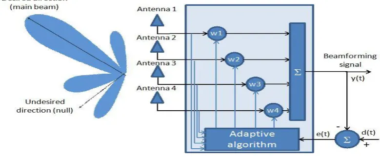
We propose a Dolph – chebyshev array method to synthesize the array beam pattern of a Non Uniform Linear Array (NULA) based on the properties of Chebyshev polynomials. For a given Side-Lobe Level (SLL), it has been proven that the Dolph-Chebyshev array provides narrowest main beam width in the array beam pattern, while for a given main beam width, it achieves the lowest SLL.
Fig 1: Functional Block Diagram of Dolph - Chebyshev Array
reduces to the binomial design. The trade-off between the side-lobe levels (SLL) and the half-power beam width (HPBW) stimulate the question answered primarily by Dolph of obtaining the narrowest possible beam width for a given side-lobe level or the smallest side-lobe level for a given beam width. This was possible by using the orthogonal functions of Chebyshev in order to design an optimum radiation pattern. However, for large number of elements this procedure becomes quite cumbersome since it requires matching the array factor expression with an appropriate Chebyshev function. To over-come this deficiency, proposed a new formulation for the design of Chebyshev arrays based on solving a system of linear equations. Iterative procedure was used to produce the desired pattern.
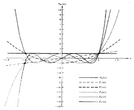
The Chebyshev polynomials:
) ( 9 120 432 576 256 ) cos( 9 ) ( 1 32 160 256 128 ) cos( 8 ) ( 7 56 112 64 ) cos( 7 ) ( 1 18 48 32 ) cos( 6 ) ( 5 20 16 ) cos( 5 ) ( 1 8 8 ) cos( 4 ) ( 3 4 ) cos( 3 ) ( 1 2 ) cos( 2 ) ( ) cos( 1 ) ( 1 ) cos( 0 9 3 5 7 9 8 2 4 6 8 7 3 5 7 6 2 4 6 5 3 5 4 2 4 3 3 2 2 1 0 z T z z z z z nu n z T z z z z nu n z T z z z z nu n z T z z z nu n z T z z z nu n z T z z nu n z T z z nu n z T z nu n z T z nu n z T nu n
)
cosh
cosh(
)
cos
cos(
)
cosh
cosh(
)
1
(
)
(
1 1 1x
n
x
n
x
n
x
T
n n1
x
1
1
x
1
x
1
8
8
)
(
3
4
)
(
1
2
)
(
)
(
1
)
(
2 4 4 3 3 2 2 1 0
x
x
x
T
x
x
x
T
x
x
T
x
x
T
x
T
)
(
)
(
2
)
(
11
x
xT
x
T
x
Fig 2: Chebyshev Polynomials T
0(x),T
1(x),T
2(x),T
3(x) and T
4(x)
A criterion that can be used to judge the relative beam width and side lobe level of one design to another is the amplitude distribution (tapering) along the source. It has been shown analytically that for a given side lobe level the Dolph-chebyshev array produces the smallest beam width between the first nulls. Conversely, for a given beam width between the first nulls, the Dolph-chebyshev design leads to the smallest possible side lobe level.
Chebyshev polynomials such as lower far outside-lobes and higher beam efficiency.
3.1 Design Equations
If elements of the array are placed along a line then such a configuration is termed as linear antenna array. The geometry is as shown in fig.3. In synthesis of linear antenna arrays the elements are considered to be isotopic radiators.
Fig 3: Geometry of the 2N-Isotropic Element Symmetric Linear Array
Placed Along the x - Axis
3.2 Array Factor
The array factor is a function of the geometry of the array and the excitation phase. By varying the separation d and/or the phase β between the elements, the characteristics of the array factor and of the total field of the array
can be controlled.
AF= 2
)
sin(
)
]
2
1
2
cos[(
1
n N
n
n
kd
n
I
Where
- Zenith angle In - Current excitation amplitude
n – Phase of the nth array element
d - The inter element spacing between the radiating element
k - Wave number of the carrier signal is k=2/
Fig 4: Array Factor for a 5 Element ULA with a Spacing of 0.5 m
3.3 Fitness Function
The Fitness Function is from the Array Factor in such that the objective of the optimization is satisfied. The general form of the fitness function is given by
FF=
Where
F0() – The pattern obtained using the proposed algorithm.
Fd() – The desired pattern.
W() - The weight vector to control the side lobe level in the cost function.
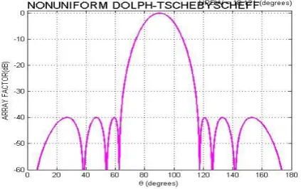
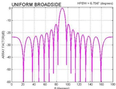
IV. SIMULATION RESULTS
Fig 5.1: Optimized Radiation pattern with Fig 5.2 : Optimized Radiation pattern with reduced side lobe level for N=8 elements reduced side lobe level for N=8 elements array for Broad side array array for Dolph – chebyshev array
0
0 90
90
0
(
)
(
)]
)[
(
F
F
dFig 5.3: Optimized Radiation pattern with Fig 5.4: Optimized Radiation pattern with
reduced side lobe level for N=15 elements reduced side lobe level for N=15 elements array for Broad side array array for Dolph – chebyshev array
Fig 5.5: Polar plot of Broad side array for N=8 Fig 5.6: Polar plot of Dolph – chebyshev array for N=8
Fig 5.7: Polar plot of Broad side array for N=1 Fig 5.8: Polar plot of Dolph – chebyshev array for N=15
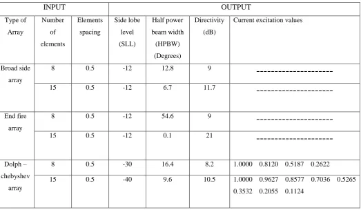
Table 1: Compression of Antenna Arrays
INPUT
OUTPUT
Type of Array
Number of elements
Elements spacing
Side lobe level (SLL)
Half power beam width (HPBW) (Degrees)
Directivity (dB)
Current excitation values
Broad side array
8 0.5 -12 12.8 9
---
15 0.5 -12 6.7 11.7
---
End fire array
8 0.5 -12 54.6 9
---
15 0.5 -12 0.1 21
---
Dolph – chebyshev
array
8 0.5 -30 16.4 8.2 1.0000 0.8120 0.5187 0.2622
15 0.5 -40 9.6 10.5 1.0000 0.9627 0.8577 0.7036 0.5265 0.3532 0.2055 0.1124
V. CONCLUSION
This research work proved the power of using Dolph – chebyshev array in solving complex problems where you have conflicting constrains. The first side lobe level which introduces Electromagnetic Interference (EMI) problems is lowered without disturbing the main beam width. The parameters obtained by applying dolph – chebyshev array. For 15element array SLL = – 40 dB, HPBW = 9.60. Dolph – chebyshev array finds the beam width and side lobe level with N=8, 15. It can be seen that the current excitation values obtained from the dolph – chebyshev for all the number of elements simulated compare to other arrays, while at the same time, the first
null – to – null beam width is slightly reduced as well as reduces the side lobe levels.
REFERENCES
[1]. A Safai-Jazi, A New Formulation for the Design of Chebyshev Arrays, IEEE Transaction on Antenna and Propagation, Vol. 42, No, 3, 1994, pp. 439-443.
[2]. K.-K. Yan and Y. Lu, Sidelobe Reduction in Array Pattern Synthesis using Genetic Algorithm, IEEE Transaction on Antennas and Propagation, vol. 45(7), pp. 1117-1122, July 2007.
[3]. R.C. Eberhat, Y. Shi, Particle Swarm Optimization: developments, applications and reeources, evolutionary computing, Proceedings of 2001 Congress on Evolutionary Computation, vol. 1,pp. 81-86,2001.
[5]. J.Kennedy and R. Eberhart, Particle swarm optimization, in Proc. IEEE Int. Conf. Neural Networks, 1995, vol.IV, pp. 1942-1948.
[6]. J.Robinson and Y. Rahmat-Samii, Particle Swarm Optimization in electromagnetics, IEEE Transaction on Antennas and Propagation, vol. 52, pp. 397-407, Feb. 2004.
[7]. Mohammed H. Bataienh, On Chebyshev Array Design Using Particle Swarm Optimization, Journal of Electromagnetic Analysis and Applications, vol.3,pp. 213-219, June 2011.
[8]. Marcano, D. and F. Duran, \Synthesis of antenna arrays using genetic algorithms," IEEE Antennas Propagat. Magazine, Vol. 42, No. 3, Jun. 2000.
[9]. Tian, Y. and J. Qian, \Improve the performance of a linear array by changing the spaces among array elements in terms of genetic algorithm," IEEE Transactions on Antennas and Propagation, Vol. 53, No. 7, 2226{2230, Jul. 2005. 7. Sayidmarie, K. H. and A. H. Aboud, \Improvement of array radiation pattern by element position perturbation," 5th International Multi-Conference on Systems, Signals and Devices, IEEE SSD, 1{6, Jul. 20{22, 2008.
[10]. Das, S., S. Bhattacherjee, D. Mandal, and A. K. Bhattacharjee , \Optimal sidelobe reduction of symmetric linear antenna array using genetic algorithm," Annual IEEE India Conference (INDICON), 1{4, Dec. 17{19, 2010.
[11]. Hussein, A. H., H. H. Abdullah, A. M. Salem, S. Khamis, and M. Nasr, \Optimum design of linear antenna arrays using a hybrid MoM/GA algorithms," IEEE Antennas Wireless Propag. Lett., in press.
AUTHORS BIOGRAPHY
Mrs. S.RUKSANA BEGUM received the B.Tech degree in Electronics and Communication Engineering from Dr. K.V. Subba Reddy College of Engineering & Tech, JNTU Anantapur, A.P in 2013. Currently, she is pursuing her (M.Tech) in G. Pullaiah College of Engg & Tech Kurnool, JNTU Anantapur, A.P. Her current research interests includes study and designing properties of antennas and its applications.
Mr. G. Ramarao received his B.Tech degree from Nagarjuna University, Guntur, India, in Electronics and Communications Engineering and Master’s degree from JNTU
college of Engineering, JNTUA,Anatapur. He worked as faculty in ECE department for 13 Years. Currently He is working as an Associate Professor of GPCET.