A Monthly Journal of Computer Science and Information Technology
ISSN 2320–088X
IJCSMC, Vol. 2, Issue. 9, September 2013, pg.120 – 127
RESEARCH ARTICLE
© 2013, IJCSMC All Rights Reserved
120
Design and Implementation of Rijndael
Encryption Algorithm Based on FPGA
K. Soumya1, G. Shyam Kishore2
1
PG Student, JITS, Karimnagar, India
2
Associate Professor, JITS, Karimnagar, India
1
[email protected]; 2 [email protected]
Abstract— With the rapid development and wide application of computer and communication networks, the information security has aroused high attention. Information security is not only applied to the political, military and diplomatic fields, but also applied to the common fields of people’s daily lives. With the continuous development of cryptographic techniques, the long-serving DES algorithm with 56-bit key length has been broken because of the defect of short keys. The "Rijndael encryption algorithm" invented by Belgian cryptographers Joan Daemen and Vincent Rijmen's had been chosen as the standard AES (Advanced Encryption Standard) algorithm whose packet length is 128 bits and the key length is 128 bits, 192 bits, or 256 bits. Since 2006, the Rijndael algorithm of advanced encryption standard has become one of the most popular algorithms in symmetric key encryption. AES can resist various currently known attacks.
I. INTRODUCTION
1.1 Motivation
Hardware security solution based on highly optimized programmable FPGA provides the parallel processing capabilities and can achieve the required encryption performance benchmarks. The current area-optimized algorithms of AES are mainly based on the realization of S-box mode and the minimizing of the internal registers which could save the area of IP core significantly. One new AES algorithm with 128-bit keys (AES-128) was realized in Verilog Hardware Description Language. The 128-bit plaintext and 128-bit key, as well as the 128-bit output data were all divided into four 32-bit consecutive units respectively. The pipelining technology was utilized in the intermediate nine round transformations so that the new algorithm achieved a balance between encryption speed and chip area, which met the requirements of practical application.
1.2 Aim of the Project
© 2013, IJCSMC All Rights Reserved
121
VHDL code. Synthesizing and implementation (i.e. Translate, Map and Place and Route) of the code is carried out on Xilinx-Project Navigator, ISE 12.1i suite.
1.3 Work Objective
Firstly, functional simulation and timing analysis of this algorithm had been achieved in the ModelSim SE PLUS 6.0 and the Quartus 7.2 platform. Then we completed the synthesis simulation of this design based on HJTC0.18um CMOS process in ASIC design and verification platform provided by Synopsys Company. The data of each column (32 bits) in the state matrix was used to be an operand of encryption, when the operation of Shift Rows and Sub Bytes were incorporated. And each round of the intermediate nine Round Transformations of encryption was processed by pipelining technology.
The results show that this new algorithm with pipelining technology and special mode of data transmission can significantly decrease the quantity of chip pins and reduce the chip area.
This standard specifies the Rijndael algorithm, a symmetric block cipher that can process data blocks of 128 bits, using cipher keys with lengths of 128, 192, and 256 bits. Rijndael was designed to handle additional block sizes and key lengths; however they are not adopted in this standard. Throughout the remainder of this standard, the algorithm specified herein will be referred to as “the AES algorithm.” The algorithm may be used with the three different key lengths, and therefore these different “flavors” may be referred to as “AES-128”, “AES-192”, and “AES-256”.
1.4 Proposed system Advantages
For maintaining the speed of encryption, the pipelining technology is applied and the mode of data transmission is modified in this design so that the chip size can be reduced.
II. SECURITY STANDARD
2.1 Advanced Encryption Standard (AES)
The Advanced Encryption Standard (AES) was published by NIST in 2001. AES is a symmetric block cipher that operates on 128-bit block as input and output data. The algorithm can encrypt and decrypt blocks using a secret key which has a key size of 256-bit, 192-bit, or 128-bit. One of the main features of AES is simplicity that is achieved by repeatedly combining substitution and permutation computations at different rounds. That is, AES encrypts/decrypts a 128-bit plaintext/ciphertext by repeatedly applying the same round transformation a number of times depending on the key size,
2.1.1 AES Cipher
For 128-bit key size, there are 10 rounds substitutions and permutations that have to be executed in AES cipher (see Table 3.1). The input 128-bit plaintext is presented in a 4x4 matrix of bytes. Thus, there are 32 bits each row and each column in the matrix. This matrix is also called State array which is illustrated in table 3.1. I, Si,j indicates a byte, where 0≤i,j ≤3. The state array is altered in each round. The input key is expanded into an
array of forty four 32-bit words, and each 4 words of the expanded key will be used in each round. The key expansion should be done before the cipher operation. Each round transformation consists of four phases as follows:
• SubBytes
• ShiftRows
• MixColumns
• AddRoundKey
Sub Bytesthe function Sub Bytes is the only non-linear function in AES. It substitutes all bytes of the state array using a LUT which is a 16x16 matrix of bytes, often called S-box.
© 2013, IJCSMC All Rights Reserved
122
In this thesis, two schemes to implement S-box are discussed, one based on Block Select RAM+, and one based on Distributed Select RAM+.
Figure 2.1 Illustration of Sub Bytes Operation
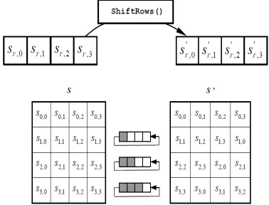
Shift Rows: In the Shift Rows transformation, the bytes in the last three rows of the State are cyclically shifted over different numbers of bytes (see Figure 3.1). The first row is not shifted. The second row is left-shifted circularly one byte. For the third row, a 2-byte circular left shift is performed. For the fourth row, a 3-byte circular left shift is performed. Since the Mix Columns and Add Round Key operations are done column by column, Shift Rows ensures that 4 bytes of one column are spread out to four different columns. Figure 2.2 illustrates the effect of the Shift Rows transformation on the State array.
Mix Columns function operates on the state column by column. Each byte of a column in state array is mapped into a new value that is a function of all the four bytes in that column as follows:
Mix Columns operation ensures a good mixing among the bytes of each column .Shift Rows and Mix
Columns together ensure that after executing the rounds all output bits depend on all input bits. Add Round Key
operation is designed as a stream cipher; all the 128 bits of state are XORed with 4 32-bit words of expanded key resulting from key expansion. Add Round Key is the only operation that involves using the key to ensure security.
The AES with 128-bit key size forward cipher operation is shown in Figure 2.2. w[i,i+3] indicates 4 words of expanded key resulting from key expansion, where 0≤ i ≤ 40 .
Figure 2.2 . AES Forward Cipher Operation (Pipelining Data Path)
Decryption is a reverse of encryption which inverse round transformations to computes out the original plaintext of an encrypted cipher text in reverse order. The round transformation of decryption uses the functions Add Round Key, Inv Mix Columns, Inv Shift Rows, and Inv Sub Bytes successively. Add Round Key is its own inverse function because the XOR function is its own inverse. The round keys have to be selected in reverse order. Inv Mix Columns needs a different constant polynomial than Mix-Columns does. Inv Shift Rows rotates the bytes to the right instead of to the left. InvSubBytes reverses the S-Box look-up table by an inverse affine
transformation followed by the same inversion over GF(28) which is used for encryption.
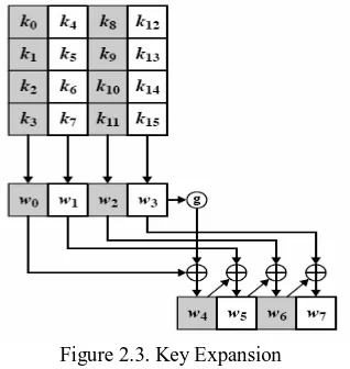
2.1.2 Key Expansion
© 2013, IJCSMC All Rights Reserved
123
In each round, AES cipher uses 4 words of the 44-word expanded key in Add Round Key transformation,. The first 4 words of the output array is nothing but the 16-byte input secret key. Except the words whose indexes are multiple of four, the other words are simply made by XORing the preceding word with the word four positions back. The words whose indexes are multiple of four go through a more complex function, called functiong before XORing with the word four positions back.
Figure 2.3. Key Expansion
The function g takes the preceding word performs a one-byte circular left shift, then it performs Sub Bytes operation on each byte of the shifted result. In the last step it takes the substituted word and XORs it with a round constant hexadecimal word array “RC(i), 0, 0, 0”, where, 1≤ i ≤10. RC(i) is given in Table in hexadecimal for each round. The purpose of using round constants is to eliminate symmetries and similarities in making the 4-word expanded key for each round.
2.2. Brief Description of Rijndael Algorithm:
Rijndael algorithm consists of encryption, decryption and key schedule algorithm. The main operations of the encryption algorithm among the three parts of Rijndael algorithm include: bytes substitution (Sub Bytes), the row shift (Shift Rows), column mixing (Mix Columns), and the round key adding (Add Round Key). The structure of Rijndael encryption algorithm Encryption algorithm processes Nr+1 rounds of transformation of the plaintext for the cipher text. The value of Nr in AES algorithm whose packet length is 128 bits should be 10, 12, or 14 respectively, corresponding to the key length of 128,192,256 bits. Only the (AES 128) encryption scheme with 128-bit keys is considered.
2.2.1Cipher
At the start of the Cipher, the input is copied to the State array using the conventions. After an initial Round Key addition, the State array is transformed by implementing a round function 10, 12, or 14 times (depending on the key length), with the final round differing slightly from the first Nr 1 rounds. The final State is then copied to the output. The round function is parameterized using a key schedule that consists of a one-dimensional array of four-byte words derived using the Key Expansion routine.
The individual transformation Sub Bytes(), Shift Rows(), Mix Columns(), and Add Round Key() – process the State and are described in the following subsections.
All Nr rounds are identical with the exception of the final round, which does not include the Mix Columns()
transformation. An example of the Cipher, showing values for the State array at the beginning of each round and after the application of each of the four transformations described in the following sections.
2.2.2. SubBytes() Transformation:
The SubBytes() transformation is a non-linear byte substitution that operates independently on each byte of the State using a substitution table (S-box). This S-box which is invertible, is constructed by composing two transformations:
1. Take the multiplicative inverse in the finite field GF(28), described; the element {00} is mapped to itself.
2. Apply the following affine transformation (over GF(2) ):
for 0 i 8 , where bi is the ith bit of the byte, and ci is the ith bit of a byte c with the value {63} or {01100011}.
Here and elsewhere, a prime on a variable (e.g., b’) indicates that the variable is to be updated with the value on
© 2013, IJCSMC All Rights Reserved
124
In matrix form, the affine transformation element of the S-box can be expressed as:
The various transformations (e.g., SubBytes(), ShiftRows(), etc.) act upon the State array that is addressed by the ‘state’ pointer. AddRoundKey() uses an additional pointer to address the Round Key.
Figure 2.4 SubBytes() applies the S-box to each byte of the State
The S-box used in the SubBytes()transformation is presented in hexadecimal. For example, if s1,1 ={53}, then the substitution value would be determined by the intersection of the row with index ‘5’ and the column with index ‘3’. This would result in s1,1having a value of {ed}.
2.2.3. Shift Rows () Transformation
In the Shift Rows() transformation, the bytes in the last three rows of the State are
This has the effect of moving bytes to “lower” positions in the row (i.e., lower values of c in a given row),
while the “lowest” bytes wrap around into the “top” of the row (i.e., higher values of c in a givenrow). Figure
2.5 illustrates the ShiftRows() transformation.
Figure 2.5 ShiftRows() cyclically shifts the last three rows in the State
2.2.4 AddRoundKey() Transformation:
In the AddRoundKey() transformation, a Round Key is added to the State by a simple bitwise XOR
operation. Each Round Key consists of Nb words from the key schedule. Those Nb words are each added into
the columns of the State, such that where [wi] are the key schedule words described, and roundis a value in the
range 0 £ round £ Nr. In the Cipher, the initial Round Key addition occurs when round = 0, prior to the first
application of the round function. The application of the AddRoundKey() transformation to the Nr rounds of the
Cipher occurs when 1 £ round £ Nr. The action of this transformation is illustrated in Fig.3. 10, where l = round
* Nb. The byte address within words of the key.
The AES algorithm takes the Cipher Key, K, and performs a Key Expansion routine to generate a key
schedule. The Key Expansion generates a total of Nb (Nr + 1) words: the algorithm requires an initial set of Nb
words, and each of the Nr rounds requires Nb words of key data. The resulting key schedule consists of a linear
array of 4-byte words, denoted [wi ], with i in the range 0 £ i < Nb(Nr + 1). The expansion of the input key into the key schedule proceeds according to the pseudo code.
2.2.5 Inverse Cipher
-© 2013, IJCSMC All Rights Reserved
125
InvShiftRows(), InvSubBytes(), InvMixColumns(), and AddRoundKey() – process the State and are described in the following subsections. The Inverse Cipher is described in the pseudo code , the array w[] contains the key schedule. The functions SubWord()and RotWord() return a result that is a transformation of the function input, whereas the transformations in the Cipher and Inverse Cipher (e.g., ShiftRows(), SubBytes(), etc.) transform the State array that is addressed by the ‘state’ pointer.
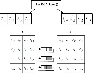
2.2.6 InvShiftRows() Transformation
InvShiftRows() is the inverse of the ShiftRows() transformation. The bytes in the last three rows of the State are cyclically shifted over different numbers of bytes (offsets). The first row, r = 0, is not shifted. The bottom three rows are cyclically shifted by Nb -shift(r, Nb) bytes, where the shift value shift(r,Nb) depends on the row number, and is given in the below equation.
Figure 2.6 InvShiftRows()cyclically shifts the last three rows in the State
III. SIMULATION RESULT
© 2013, IJCSMC All Rights Reserved
126
RTL SCHEMATICSThis synthesis is performed by Xilinx 9.2. The RTL schematic shown above is a proposed 32 bit. It consists of input signals, clock signal, reset signal and one output signal. Here input signals are mentioned with iteretion(5:0), key_in(31:0)and output signal is mentioned with key_out(31:0).
© 2013, IJCSMC All Rights Reserved
127
IV. FUTURE SCOPE
Advanced Encryption Standard (AES) is the most secure symmetric encryption technique that has gained worldwide acceptance. The AES is an efficient cryptographic technique that includes generation of ciphers for encryption and inverse ciphers for decryption. Higher security and speed of encryption/decryption is ensured by operations like Sub Bytes (S-box). Sub Bytes and Key Scheduling. Extensive research has been conducted into development of S-box /Inv. S-Box and Mix Columns/Inv. Mix Columns on dedicated ASIC and FPGA to speed up the AES algorithm and to reduce circuit area. This is an attempt, to survey in detail, the work conducted in the aforesaid fields. The prime focus is on the FPGA implementations of optimized novel hardware architectures and algorithms.
V. CONCLUSION
A FPGA implementation of area-optimized AES algorithm which meets the actual application is proposed in this project. After being coded with Verilog Hardware Description Language, the waveform simulation of the new algorithm was taken in the ModelSim SE PLUS 6.0 and Quartus 7.2 platform. Ultimately, a synthesis simulation of the new algorithm has been done.
REFERENCES
[1] J.Yang, J.Ding, N.Li and Y.X.Guo,“FPGA-based design and implementation of reduced AES algorithm”
IEEE Inter.Conf. Chal Envir Sci Com Engin(CESCE).,Vol.02, Issue.5-6, pp.67 70, Jun 2010.
[2] A.M.Deshpande, M.S.Deshpande and D.N.Kayatanavar,“FPGA Implementation of AES Encryption and
Decryption”IEEE Inter.Conf.Cont,Auto,Com,and Ener., vol.01,issue04, pp.1-6,Jun.2009.
[3] Hiremath.S. and Suma.M.S.,“Advanced Encryption Standard Implemented on FPGA” IEEE Inter.Conf.
Comp Elec Engin.(IECEE),vol.02,issue.28,pp.656-660,Dec.2009.
[4] Abdel-hafeez.S.,Sawalmeh.A. and Bataineh.S.,“High Performance AES Design using Pipelining
Structure over GF(28)” IEEE Inter Conf.Signal Proc and Com.,vol.24-27, pp.716-719,Nov. 2007.
[5] Rizk.M.R.M. and Morsy, M., “Optimized Area and Optimized Speed Hardware Implementations of AES
on FPGA”, IEEE Inter Conf. Desig Tes Wor.,vol.1,issue.16,pp.207-217, Dec. 2007.
[6] Liberatori.M.,Otero.F.,Bonadero.J.C. and Castineira.J. “AES-128 Cipher. High Speed, Low Cost FPGA