IJEDR1504085
International Journal of Engineering Development and Research (www.ijedr.org)520
Interleaved Fly Back Micro-Inverter with Primary
Side Current Control For PV System
Mamidi Bharathi Assistant Professor
D.M.S.S.V.H. College of Engineering, Machilipatnam
________________________________________________________________________________________________________
Abstract - In this paper, the interleaved fly back inverter is proposed following the topology has been broadly utilized for PV system tied small scale inverter applications. The small scale inverter arrangement permits controlling each photovoltaic (PV) module freely and diminishing the crisscross misfortune, which is regular in string and utility inverters. Fly back inverter generally works in intermittent conduction mode (NCM) or limit conduction mode (LCM) because of its straightforwardness in controller outline. In this study, the controller has been intended for continuous conduction mode (CCM) operation keeping in mind the end goal to diminish part push and build power thickness. The present control depends on the essential side, which is an aberrant regulation for the network outpouring. A little flag model is likewise created for the controller combination. Reproduction confirms the execution of the proposed inverter.
Keyword - Continuous conduction mode, Intermittent conduction mode, PV module.
________________________________________________________________________________________________________
I.INTRODUCTION
PV smaller scale inverter is getting to be main stream because of unsolvable brought together most extreme power point following (MPPT) confounding issue amid incomplete shading circumstances [1-4]. This confounds impact causes a lot of power misfortune as the PV modules in arrangement association are not working at their particular greatest influence point (MPP). Module incorporated converter system is hence proposed to conquer the issue [5]. With every board is streamlined with its own particular MPP Tracker (MPPT), the determination is higher. In this manner the system accomplishes higher effectiveness. Such systems are called as AC Modules (ACM), module coordinated converter (MIC) or smaller scale inverters. A few smaller scale inverter topologies are presented for PV applications. Transformer-less ones came up for its little size, yet they have issue with the board's parasitic capacitor [6]. Likewise a DC-join capacitor is required in the middle of the inverter and the converter. Powerlessness to scale its yield voltage into a few times higher additionally makes the topologies unrealistic to serve in nations with high system voltage. To defeat the voltage boosting issue, falling disconnected converter to an inverter is proposed [7]. It doesn't just comprehend the voltage issue; it additionally has high effectiveness and long lifetime.
IJEDR1504085
International Journal of Engineering Development and Research (www.ijedr.org)521
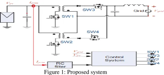
Figure 1: Proposed systemThis paper offers a topology for interleaved fly-back miniaturized scale inverter sharing two regular switches and matrix side channel with different converters from diverse boards. To do as such, essential current control plan is required [8].
Figure 2: Multiple fly back micro-inverter interconnected
On the other hand, the present streaming at the essential side is an exchanging sign after the exchanging recurrence. This represents a trouble issue to execute computerized control. In this way this paper additionally proposes setting a channel on the input way to smoothen the sign while as yet keeping up great control result.
II.PROPOSED INTERLEAVED FLY BACK MICRO-INVERTER
The proposed topology's schematic is appeared in Figure 1. The power is drawn from the PV board and its capacitor through the power train in changing way to bolster the system. The capacitor arrives to bolster board voltage and channel its energy when the topology is quickly dormant to expand the yield. Keeping in mind the end goal to accomplish the individual MPP, the essential current is controlled to shape its optional side current into sinusoid waveform. In this way the system can be built as appeared in Figure 2. In this topology, two transformers are utilized and work independently. SW1 is utilized alongside its transformer amid the positive half cycle with SW3 initiated. The other two switches are impaired amid this half period. Furthermore, when the control system recognizes negative voltage from the matrix, SW1 and SW3 are incapacitated. In the negative half, SW2 is utilized for the forming and SW4 remains empowered.
To accomplish free MPPT and decrease the part tallies, the brace side segments are intended to be shared by a gathering of parallel joined inverter units. Figure 2 shows the basic focuses where alternate modules can bury associated from their individual HT, CT, and BT joints to the lattice side switches and channel. The microcontroller is shared amongst the module converters to the extent its ability goes.
2.1 Control Structure
The general control system chart is appeared in Figure 3.
Figure 3: Proposed overall control system
IJEDR1504085
International Journal of Engineering Development and Research (www.ijedr.org)522
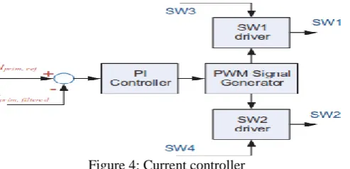
Figure 4: Current controllerHence one microcontroller can deal with various converters to the extent its ability goes. With a specific end goal to minimize module utilization of the microcontroller, stand out heartbeat width adjustment (PWM) module is used per converter. As needs be, the current control system takes the reference signal, as well as SW3 and SW4 empowering signal too.
Figure 5: Dynamic model equivalent circuit
The momentum controller part contains a PI controller, PWM signal generator, and SW1 and SW2 driver. The initial two parts are evidently inserted in the microcontroller. This present controller chart is appeared in Figure 4. The controller takes the reference signal from MPPT calculation and contrasts it and the separated exchanging signal. The control sign is bolstered to PWM module where it creates PWM sign to switch driver IC. The driver for SW1 takes SW3 enactment signal into its empowering pin and SW4 is as needs be for SW2.
III.ELEMENT MODELING AND CONTROL DESIGN
3.1 Photovoltaic Model
Normal for a photovoltaic is nonlinear, particularly at its MPP. An expression for the PV current is appeared as in mathematical statement (1) [13].
𝑖𝑝𝑣(𝑡) = 𝐼𝑝𝑣 − 𝐼𝑜 (𝑒𝑉𝑝𝑣+𝑅𝑠𝑖𝑝𝑣 𝑉𝑡 𝑎 − 1) −𝑉𝑝𝑣+𝑅𝑠𝑖𝑝𝑣
𝑅𝑝 (1)
where pv I and 0 I are the output current and saturation current of a module, Vt NsTkq-1 is the thermal voltage with s N cells connected in series, k is the Boltzmann constant, q is the electron charge, T is the cell temperature, s R is the equivalent shunt resistance, and a is the ideality constant of the diode.
Considering that the system for the most part works at MPP, the PV module has been linearised around its MPP as appeared in Figure 5 [8, 9]. The PV board is spoken to as the DC voltage source and a resistor. The network is supplanted with a fluctuating DC voltage source subsequent to, if the system works appropriately, the topology is just presented to positive optional side voltage. The red rings imply current sensors with its bearing from dark line on top to red line on top.
3.2 Fly back Inverter Modeling
Small signal averaged model approach is used for modeling the inverter. Equation (2)-(5) shows the basic relationship between each parameter in the system. Each of the parameters is delineated in Figure 5. The bar symbol signifies average variable.
𝑉𝐿𝑚= 𝑑. 𝑉𝑖𝑛 − 1−𝑑
𝑛 . |𝑉𝑔𝑟𝑖𝑑| (2)
𝑖𝑝𝑣= 𝑖𝑐+ 𝑖𝑝𝑟𝑖𝑚 (3)
𝑖𝑝𝑟𝑖𝑚= 𝑑. 𝑖𝐿𝑚 (4)
𝑉𝑖𝑛 = 𝑉𝐶𝑝𝑣+ 𝑉𝑅𝑐𝑝𝑣
where Lm v is the magnetizing inductor voltage, d is the duty ratio enacted on SW, in v is the panel’s terminal voltage, n is the transformer turns ratio, grid V is momentarily grid voltage, pv i is the panel current, c i is the capacitor current, prim i is the switching current, Cpv v is the capacitor voltage, and Rcpv v is the capacitor’s ESR voltage.
The average variables in the mathematical statements above is isolated into two sections for small signal modeling demonstrating as appeared in comparison (6). The mathematical statements above are then utilized for growing second-order state space equation comparison as in mathematical statement (7). The cap image connotes little changes in the variable and the capital means its linearised point. The model is then constructed by parameters in Table 1 for control outline reason.
IJEDR1504085
International Journal of Engineering Development and Research (www.ijedr.org)523
[𝑣𝐶𝑝𝑣̂𝑖̂𝐿𝑚] = 𝐴 [𝑣𝐶𝑝𝑣̂𝑖̂𝐿𝑚] + 𝐵𝑑̂ (6)𝑖̂ = 𝐶 [𝑠𝑤 𝑖𝐿𝑚̂ 𝑣𝐶𝑝𝑣
̂] + 𝐷𝑜𝑑̂ (7)
A =[
−𝐷2𝑅𝑝𝑣𝑅𝐶𝑝𝑣
𝐿𝑚(𝑅𝑝𝑣+𝑅𝐶𝑝𝑣) −𝐷𝑅𝑝𝑣 𝐿𝑚(𝑅𝑝𝑣+𝑅𝐶𝑝𝑣) −𝐷𝑅𝑝𝑣 𝐶𝑝𝑣(𝑅𝑝𝑣+𝑅𝐶𝑝𝑣) −1 𝐶𝑝𝑣(𝑅𝑝𝑣+𝑅𝐶𝑝𝑣)
]; (8)
𝐵 = [
𝑉𝐶𝑝𝑣𝑅𝑝𝑣−2𝐷𝐼𝐿𝑚𝑅𝑝𝑣𝑅𝐶𝑝𝑣+𝑉𝑝𝑣𝑅𝐶𝑝𝑣 𝐿𝑚(𝑅𝑝𝑣+𝑅𝐶𝑝𝑣) +
|𝑉𝑔| 𝐿𝑚𝑛
−𝐼𝐿𝑚𝑅𝑝𝑣 𝐶𝑝𝑣(𝑅𝑝𝑣+𝑅𝐶𝑝𝑣)
]; (9)
C =[𝐷 0]; (10)
D =𝐼𝐿𝑚; (11)
3.3 Signal Filter
A simple resistive-capacitive filter is inserted in the feedback path to smoothen the signal. Figure 6 illustrates the proposed filter. Rs represent infinity resistance of control devices. The filter transfer function is derived as shown in equation (9) where R �1
k� and C � 0.06 �F. Although this additional filter introduces delay in the control loop, this pole later is compensated by a
zero in the controller. 𝐻𝑓𝑖𝑙𝑡𝑒𝑟(𝑠) =
1 𝑅. 𝐶. 𝑠 + 1
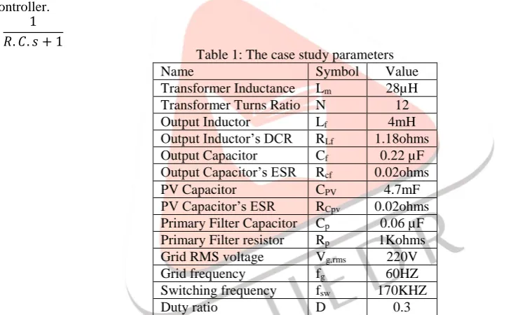
Table 1: The case study parameters
Name Symbol Value
Transformer Inductance Lm 28µH Transformer Turns Ratio N 12
Output Inductor Lf 4mH
Output Inductor’s DCR RLf 1.18ohms
Output Capacitor Cf 0.22 µF
Output Capacitor’s ESR Rcf 0.02ohms
PV Capacitor CPV 4.7mF
PV Capacitor’s ESR RCpv 0.02ohms Primary Filter Capacitor Cp 0.06 µF Primary Filter resistor Rp 1Kohms Grid RMS voltage Vg,rms 220V
Grid frequency fg 60HZ
Switching frequency fsw 170KHZ
Duty ratio D 0.3
This similar transfer function exists in both [8] and [12] as part of PI type 2 controllers, but placing in the feedback path makes it possible to control the system using digital controller.
Figure 6: RC filter
The signal sensed from this filter can also be used for MPPT purpose. This transfer function is then added to the switching current’s model as derived in the equation (7) and (8) directly.
3.4 Control Design
IJEDR1504085
International Journal of Engineering Development and Research (www.ijedr.org)524
𝑃𝑔(𝑡) = 2. 𝑉𝑟𝑚𝑠𝐼𝑟𝑚𝑠𝑆𝑖𝑛2𝝎𝒕 (12)
𝑃𝑝𝑣(𝑡) = 𝑣𝑝𝑣(𝑡). 𝑖𝑠𝑤(𝑡) (13)
𝑖𝑠𝑤(𝑡) =
2.𝑉𝑟𝑚𝑠𝐼𝑟𝑚𝑠
𝑉𝑝𝑣 . 𝑆𝑖𝑛
2𝝎𝒕 (14)
𝐶(𝑠) = 1.33 (1+4.9𝑒−5.𝑠
4.9𝑒−5.𝑠 ) (15)
Figure 7: Closed loop step response
IV.SIMULATION &RESULTS
The system is simulated using PSIM software with snubber circuit and parasitic components. The controller designed in the previous section is implemented as in equation (13) and described in section 2.
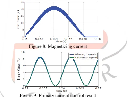
Figure 8: Magnetizing current
Figure 9: Primary current control result
The simulation results are shown in Figure 8 to Figure 11. However, it is in DCM during the time it rises from zero as it just starts charging the magnetizing inductor. Figure 9 illustrates the simulation result for the primary current. The control objective is achieved as the averaged switching current follows its rotating reference signal closely. Figure 10 shows the grid voltage and the current feeding into the grid. Although the grid current follows grid voltage closely, there are noticeable distortions around polarity shifting points. This however does not affect its THD significantly.
Figure 10: Grid current control result Primary Current (A) Grid current’s THD satisfyingly results in only 2 percent compared to the grid code of 5 percent [14].
IJEDR1504085
International Journal of Engineering Development and Research (www.ijedr.org)525
Additionally, the feedback filter does not heavily affect the performance as well since its PF is at 99.9 percent in Figure 10. This shows improvement from previous literature work [8, 12].Figure 11: Primary Current Reference Shifting
Figure 11 shows the simulation results with the system experiences a peak value shift at 0.2s from 8.4 A to 4.4 A. Both the primary current and output current adjust into their respective transient operation quickly using just a grid cycle time.
V.CONCLUSION
In this work, a fly back inverter with sharing developing switches has been proposed alongside its control plan. The fundamental motivation behind this work is to control the essential current sign keeping in mind the end goal to utilize miniaturized scale controller for network tied operations. A low recurrence RC channel is included as a component of the criticism way. A second request little flag model is then created for control outline reason alongside the channel model. MATLAB is utilized a while later for control outline. The framework is then exhibited by reenactment in PSIM programming with commonsense model. The reproduction results in great execution fulfilling the lattice codes with 2% THD, and 99.9% PF. The control system likewise adjusts quickly with change in reference top quality as impact from MPPT calculation.
VI.REFERENCES
[1] Y. Du and D. D.-C. Lu, "Battery-integrated boost converter utilizing distributed MPPT configuration for photovoltaic systems," Solar Energy, vol. 85, pp. 1992-2002, 2011.
[2] H. Häberlin, "Solar Modules and Solar Generators," in Photovoltaics System Design and Practice, ed: John Wiley & Sons, Ltd, 2012, pp. 127-221.
[3] A. Mäki and S. Valkealahti, "Power Losses in Long String and Parallel-Connected Short Strings of Series-Connected Silicon-Based Photovoltaic Modules Due to Partial Shading Conditions," IEEE Trans. on Energy Conv., vol. 27, pp. 173-183, 2012.
[4] H. Patel and V. Agarwal, "MATLAB-Based Modeling to Study the Effects of Partial Shading on PV Array Characteristics," IEEE Trans. on Energy Conv., vol. 23, pp. 302-310, 2008.
[5] J. J. Bzura, "The AC module: An overview and update on self-contained modular PV systems," in Power and
Energy Society General Meeting, 2010, pp. 1-3.
[6] R. Teodorescu, M. Liserre, and P. Rodríguez, "Photovoltaic Inverter Structures," in Grid Converters for Photovoltaic and Wind Power Systems, ed: John Wiley & Sons, Ltd, 2011, pp. 5-29.
[7] C. Rodriguez and G. Amaratunga, "Long-Lifetime Power Inverter for Photovoltaic AC Modules," IEEE Trans. on Ind. Elec., vol. 55, pp. 2593-2601, 2008.
[8] T. V. Thang, N. M. Thao, J. Jong-Ho, and P. Joung- Hu, "Analysis and Design of Grid-Connected Photovoltaic Systems
With Multiple-Integrated Converters and a Pseudo-DC-Link Inverter," IEEE Trans. on Ind. Elec., vol. 61, pp. 3377-3386, 2014.
[9] F. F. Edwin, W. Xiao, and V. Khadkikar, "Dynamic Modeling and Control of Interleaved Flyback Module-Integrated Converter for PV Power Applications," IEEE Trans. on Ind. Elec., vol. 61, pp. 1377-1388, 2014.
[10] X.-F. He, Z. Zhang, and X. Li, "An optimal control method for photovoltaic grid-connected interleaved fly back micro-inverters to achieve high efficiency in wide load range," in 7th In'l Power Elec. and Motion Control Conf. (IPEMC), 2012, pp. 1429-1433.
[11] Z. Zhang, X.-F. He, and Y.-F. Liu, "An Optimal Control Method for Photovoltaic Grid-Tied- Interleaved Fly back Micro inverters to Achieve High Efficiency in Wide Load Range," IEEE Trans. on Power Elec., vol. 28, pp. 5074-5087, 2013.
[12] Y. Li and R. Oruganti, "A Low Cost Flyback CCM Inverter for AC Module Application," IEEE Trans.on Power Elec., vol. 27, pp. 1295-1303, 2012.
[13] M. G. Villalva, J. R. Gazoli, and E. R. Filho, "Comprehensive Approach to Modeling and Simulation of Photovoltaic Arrays," IEEE Trans. on Power Elec., vol. 24, pp. 1198-1208, 2009.