409 | P a g e
Analysis of Voltage-Frequency (VF) Droop Control
Method for AC Microgrid Application
Shalini Raosaheb Borade
1, Prof. A. M Jain
21
PG Student, Department of Electrical Engineering , KKWIEER, Nashik,( India)
2
Professor, Department of Electrical Engineering, KKWIEER, Nashik, (India)
ABSTRACT
Integration of microgrids into the main power systems imposes major challenges regarding reliable operation
and control. Reliable operation means to be able to manage the microgrid in its two modes of operation; grid-
connected and islanded, as well as handling the transition between these two modes. Several control strategies
have been established in this area. Microgrid based on droop control can achieve automatically adjust voltage
and frequency, without the aid of communication, which can improve system reliability, and easy to implement
micro-power and load plug and play. We designed specifically simulation circuit of the droop control strategy
for a micro grid. This project utilizes droop based control method due to its advantages of great flexibility, no
communication needed, high reliability, and free laying. A droop control scheme uses only PCC voltage and
current to detect changes in the system and adjust the operating points of the system accordingly. The droop
control uses the real power out of a generator to calculate the ideal operating frequency. Hear used droop
control technique to enhance power sharing and the voltage/ frequency synchronization are real power–
frequency (P–F) droop control and reactive power–voltage magnitude (Q– V) droop control. In this project, one
PV unit is controlled to set the voltage and frequency of the microgrid, VF mode. Droop control is reviewed and
simulations in MATLAB R2014a will be used to determine the effectiveness of the droop controller for
microgrid application..
Keywords: Distributed Generators (DGs), Droop Control, Distributed Energy Storage Devices
(DESUs), Microgrid(MG) and
Point of Common Coupling (PCC)
I. INTRODUCTION
The implementation of distributed generation (DG) has been highly increasing. Compared to the conventional
centralized power generation, DG units have many advantages such as higher energy utilization efficiency,
flexibility in installation location, and less power transmission losses. Nowadays microgrid is one of the most
up-to-date and important topics in the scope of power systems [1]. The microgrid concept was first proposed in
410 | P a g e
cluster of DG units and loads, serviced by a distribution system, and can operate in two modes: grid-connectedmode and islanded mode. The basic functions of a microgrid are [4]:
1. Regulating the microgrid’s voltage magnitude and frequency within their normal ranges during autonomous
mode.
2. Controlling active power and reactive power flow from DG units to loads while working in autonomous
mode.
3. Managing power flow between microgrid and the main grid during grid-connected mode.
4. Providing a smooth transition between islanded mode and grid-connected mode.
Most DG units are connected to the microgrid through DC/AC inverter interface. Thus, by proper control of
those inverters, microgrid energy management is sufficiently accomplished. The fundamental control variables
of a microgrid are active power, reactive power, voltage, and frequency. In grid connected mode, the microgird
frequency and the voltage at the Point of Common Coupling (PCC) are predominantly dictated by the main grid.
In this case, the major function of the microgrid control is to manage both active and reactive powers produced
by the DG units and the load requirements. Injecting reactive power into the main power grid can be used to
provide ancillary services such as power factor correction, elimination of harmonics, or voltage control. In some
cases, the utility may not permit voltage control at PCC by DG units to prevent interfering with similar actions
provided by the utility.
In islanded mode, the microgrid works totally independent. Therefore, this situation is more difficult than being
connected to the main grid, as maintaining load-supply equilibrium necessitates the application of precise load
sharing mechanisms to adjust and equilibrate any unexpected power mismatches. Neither Voltages nor
frequency of the microgrid are still determined by the main grid, thus they must be controlled by the DG units.
Power balance is guaranteed either by local controllers using local data, or using a centralized controller that
calculates and sends set points to local controllers of various DG sets and controllable loads ensuring that all DG
units share in feeding the load in a pre-determined way. Any deviation in the magnitude, phase shift or
frequency of the output voltage of one of the DG units can lead to severe circulating currents [5]. For microgrid
control, two unique opposite approaches are recognized: centralized or decentralized. In centralized control
methodology vast communication among the central controller and local controllers is required. Any loss of
communication link or faulty operation of the master unit can shut down the entire system [6]. However, in the
decentralized control methodology, each unit is controlled using its local controller that receives only local
measurements without considering other system variables or other controllers’ actions.
Various techniques have been adapted to parallel inverters [7]. They have different architectures and modes of
operation. In master/slave techniques, a voltage controlled inverter is used as a master unit to maintain proper
output sinusoidal voltage and generate a distributive current command to be tracked by the current controlled
slave inverters [8]. Another technique is the current/power sharing where the total load current is measured then
divided by the number of inverters to get the mean inverter current. Subsequently, the difference between the
411 | P a g e
frequency/voltage droop based technique has been accepted as the most popular decentralized control strategy[9]. In this method the inverters operate in parallel with no auxiliary inter connections as the above methods.
This technique allows the independent inverters to share the load in proportion to their capacities. In this paper,
droop control method is adopted for the proposed microgrid with smooth transition capability between the grid
connected and islanded modes of operation.
There are many practical concerns associated with microgrid operation such as interconnection patterns among
microgrids and the main grid; voltage-control strategies within a microgrid; and frequency control during
islanded operation. This project surveyed on appropriate power sharing and frequency-control schemes for
optimal performance of a microgrid with manifold DGs. The reason to concentrate on optimum power sharing
is, for the reliable operation of microgrid to optimize the voltage profile and also to reduce losses. Appropriate
power sharing in island mode can be acquired only by means of control schemes. Among various control
schemes, this paper highlighted on droop control techniques. The droop control types such as conventional
droop control (P-F droop control & Q-V droop control) and modified conventional droop control (P-V & Q-F
droop control, V-F droop control and Angle droop) are spotted in this work.
The primary focus of droop control is to retain the fundamental frequency & the voltage magnitude of microgrid
with manifold DGs in autonomous mode so that the appropriate powers are shared. Frequently used droop
control technique to enhance power sharing and the voltage/ frequency synchronization are real power–
frequency (P–F) droop control and reactive power–voltage magnitude (Q– V) droop control. Consequently its
implementation is simple and it empowers decentralized control of manifold distributed generations (DGs) [12].
Previous studies on the use of droop control within the context of controlling distributed generation focus on the
idea those inverters will tie the energy source into the electrical system. Studies on control schemes for power
balance, fault tolerance and system stability have been conducted but focus on the control of the power
electronics topology and switching schemes to obtain results.
II. OVERVIEW OF DROOP CONTROL METHOD
The droop control method is based on locally measured data, does not depend on communication signal,
accordingly eliminating the difficulties imposed by physical location. The droop method has other advantages
such as great flexibility, high reliability, simple structure, easy implementation, free laying, and different power
ratings. In power grids, the active power and the reactive power have strong coupling with the frequency and the
voltage, respectively. Accordingly, the relationship between the active power/frequency and the reactive
power/voltage can be expressed as,
where 𝑓𝑜 and 𝑉𝑜 are the rated values for the system frequency and voltage, respectively, where f and V are the
measured frequency and voltage of the DG unit, respectively, and 𝑃𝑜and 𝑄𝑜 are the momentary set points of the
412 | P a g e
reactive powers, respectively, K𝑃𝑓 and 𝐾𝑄𝑉 symbolize the droop coefficients which are chosen relying on steadystate performance criteria. The droop coefficients are calculated from,
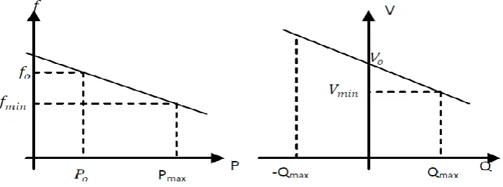
where 𝑃max and 𝑄max are the maximum active and reactive powers delivered by the inverter, respectively, Δ𝑓 and
Δ𝑉 are the maximum allowable frequency and voltage magnitude deviations, respectively. According to the EN
50160, Δ𝑓 should be within ± 2% of the nominal frequency, while Δ𝑉 should not exceed ± 10% of the nominal
voltage magnitude. A conventional P-f and Q-V droop characteristics are shown in Fig. 1(a) and Fig. 1(b),
respectively. At nominal voltage operating conditions, the DG units are supposed not to deliver any reactive
power to the main grid, which means supplying active power at unity power factor in this working condition. In
Fig 1(a), 𝑓min and 𝑉min identify the minimum acceptable frequency and voltage of the DG unit, respectively.
Figure 1: Conventional droop characteristics (a) P-f droop (b) Q-V droop
For several DG units connected in parallel constituting a microgrid, the load power sharing depends on the slope
of the droop characteristics. The main idea is that when there is an increase in the load, the frequency reference
is decreased. Similarly, reactive power is shared using the droop characteristic of the voltage magnitude. The
mechanism of active power sharing based on droop control is,
Similarly, the mechanism of reactive power sharing using droop control is,
III. THE PROPOSED CONTROL SYSTEMS (VF control mode)
Two control technique approaches are used to operate the inverter; active-reactive power (PQ) control mode and
voltage-frequency (VF) control mode. The inverters are usually operated in PQ mode when the microgrid works
in grid connected status. The references of active and reactive powers for each inverter may be predetermined
413 | P a g e
(MPPT) based control strategy. On the other hand, during islanded mode of operation, at least one inverter mustbe operated in VF mode and synchronized with the main grid, while the other DG units can still be controlled in
PQ mode. When the microgrid moves to the islanded mode, the system will be unstable if all the inverters
operate in PQ control mode because we have to set up the system frequency/voltage using this VF operated
inverter, as well as properly share the load power among all the parallel inverters.
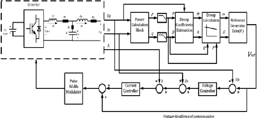
In this case, the reference signals of voltage and frequency are extracted directly from the droop characteristics.
The block diagram of the droop control system for the VF inverter is shown in Fig. 2. Inverter output voltage
and current are measured, thus calculating active and reactive powers of the inverter and processing them
through the inverter droop characteristics represented by (1) and (2) to obtain the voltage and frequency
reference, V and F.
Figure 2: Droop based control system for the VF inverter
Block diagram of the proposed droop control scheme is shown in figure 2. If this block diagram is compared to
the block diagram of traditional droop control based inverters in or in some other articles, then the only
prominent difference will be the droop coefficients estimation block. The traditional droop control scheme uses
only fixed droop values for their droop control mechanism regardless of any change in output active and
reactive power demand. While this thesis work has proposed a new droop control technique and this new
estimated droop control block uses an online estimation mechanism for droop values rather than using fixed
values (conventional method) and then these values are adapted by droop control block to control active and
reactive power flow.
414 | P a g e
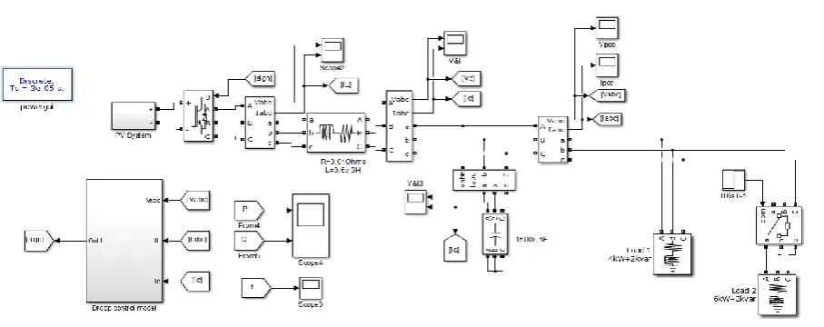
Figure 3: Single line diagram of the proposed microgrid system
Fig. 3 portrays the single line diagram of the proposed microgrid system with three electronically interfaced DG
units. The three DG units are assumed identical. A base load and a switched load are connected to a common ac
bus. The microgrid is connected to the utility through a STS. For the sake of simplicity, the DC bus voltage of
each unit is assumed constant and equal. The system parameters are listed in Table 1.
Inverter one operates in VF control to generate the reference voltage to be followed by the other DG units in the
microgrid. Allowing this inverter to work as grid forming in both grid-connected and islanded operation
provides the smooth transition required between the two operation modes of the microgrid. On contrary,
inverters two and three operate in PQ control during the grid-connected and the islanded operation modes of
microgrid. The microgrid system presented in Fig. 3 is simulated using the MATLAB R2014a software
package. The droop characteristics of each unit are adjusted to supply rated active power at rated frequency and
zero reactive power at nominal voltage. The dynamic performance of the proposed control strategy is tested
under different modes of operations and dynamic load change.
a) Grid -connected mode
In this mode, the main grid dictates its voltage and frequency while the microgrid simply exchanges real and
reactive powers. When the load requirement is less than the rated capacity of DGs units, the excess power flows
into the main grid. While when the load requirement is greater than the rated capacity of DGs units, the grid
feeds the deficit power. As the frequency is set by the main grid, each DG unit is supposed to deliver its rated
active power regardless the loading condition. On the other hand, the load reactive power is mainly supplied by
the main grid and the filtering capacitors of the microgrid inverters. Fig. 4(c) shows the reactive power fed from
the first DG unit, controlled in VF mode. These results reveal the success of the proposed droop based control
415 | P a g e
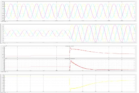
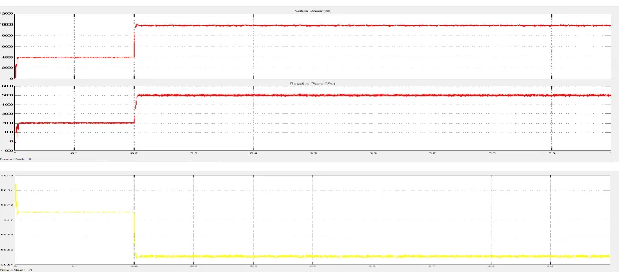
Figure 4: (a) PCC voltage, (b) load current, (c) active and reactive power sharing & (d) frequency of the
microgrid during the grid-connected mode.
b) Islanded mode
In islanded mode, the total power demand of the load has to be supplied by the DG units while regulating the
system frequency and voltage. Since the PCC voltage constant after islanding, as indicated Fig. 5(a), the droop
416 | P a g e
Figure 5: (a) PCC voltage, (b) load current, (c) active and reactive power sharing & (d) frequency of the
microgrid during the Islanded mode
Table 1.The system parameters
V. CONCLUSION
The new control strategy of the DG interface system greatly influences the microgrid performance. In this paper,
the droop characteristics of frequency-versus active power and voltage-versus-reactive power along with
Modified droop control (V-F droop control) are adapted to control performance of AC microgrid. The VF
417 | P a g e
grid-connected to islanded mode without the need to wait for the islanding detection signal or mode switching.Also properly share the load power among all the parallel inverters and having constant PCC Voltage in both
condition. This action results in autonomous operation of the microgrid and enhancing the system reliability.
Simulation results show that the proposed system succeeded in regulating the voltage and the frequency of the
microgrid.
REFERENCES
[1] Bill Moran, Mark Lorentzen, “Assessing the Role of Energy Efficiency in Microgrids”, TRC Solutions,
2016
[2] Jiravan M, “Energy Storage for stability of microgrids”, Electric power, Universite de Grenoble, 2014. [3] Michael J. Johnston, “Energy Storage Systems and Microgrids”, NECANOW 2017
[4] X Sun, Y Hao, Q Wu, X Guo,B Wang, “A Multifunctional and Wireless Droop Control for Distributed Energy Storage Units in Islanded AC microgrid Applications”, IEEE Transactions on Power Electronics,
2016
[5] Xiao Zhao-xia,Fang Hong-wei, “Impacts of P-f and Q-V Droop Control on MicroGrids Transient Stability”,
Intl. Conf. on Applied Physics and Industrial Engineering, 2012, Physics Procedia, Science direct.
[6] Wen-Yeau Chang, “The State of Charge Estimating Methods for Battery: A Review”, Hindawi Publishing
Corporation, ISRN Applied Mathematics, 2013
[7] L Zheng, C Zhuang, J Zhang and X Du, “An Enhanced Droop Control Scheme for Islanded Microgrids”,
International Journal of Control and Automation, VOL 8, 2015.
[8] Omid Palizban, “Distributed Control Strategy for Energy Storage Systems in AC Microgrids”, University of Vaasa, Faculty of Technology, Energy Technology, Finland
[9] Raji Atia, Noboru Yamada, “Distributed Renewable Generation and Storage System Sizing Based on Smart Dispatch of Microgrids”, Energies 2016
[10] E. Hossain, E. Kabalci, R. Bayindir, Ronald Perez, “ A Comprehensive Study on Microgrid Technology”,
International Journal Of Renewable Energy Research, Vol. 4, 2014
[11] K C. Soni, Firdaus F. Belim, “Microgrid during Grid-connected mode and Islanded mode - A Review”,
National Conference on Recent Research in Engineering and Technology, 2015
[12] S. S. Vignesh, R. S. Sundaramoorthy, A. Megallan, “The combined V-F , P-Q and Droop control of PV in