TLM based AMBA AXI4 protocol implementation using
verilog with UVM environment
Harini H G1 , Kavitha V2
1
M.Tech Student, Department of Electronics and Communication Engineering CMR Institute of Technology, Bangalore, affiliated to VTU Belgaum India
2
Ph.D scholar, Department of Electronics and Communication Engineering Jain University Bangalore India
Abstract
During the entire phase of any project verification plays an important role. Most of the time and the effort are spend on verification. Transaction-level modeling (TLM) and Bus Functional modeling (BFM) are used in order to reduce this effort. Transaction-level modeling (TLM) is a technique used to describe the system by using the standard function calls which defines all the transactions which are required to verify the functionality of the system at the architecture level. Abstraction level rises by using this technique. Simulation speed and the modeling speed are more than the Register transfer level (RTL) Before building and testing the actual hardware a Bus Functional modeling (BFM) or Transaction Verification Models (TVM) are used to simulate the bus transactions. Standard buses enable the reusability of IP cores. Standard busses include AMBA from ARM, CORE CONNECT from IBM and others. There are various versions of AMBA like AMBA 1.0 to AMBA 5.0 in which AXI4 lite is an advanced extensible interface targeted for register style interface, it comes under AMBA4.0 specification. AXI4 is having excellent throughput, than AHB.
This project introduces the development of AXI4 protocol and verifying the same by UVM based test bench which supports TLM modeling.
Keywords: Transaction Level modeling (TLM), Advanced
Extensible interface (AXI), Advanced Micro Controller Bus Architecture (AMBA), Methodology (OSVVM), Universal Verification Methodology (UVM), Verification Methodology Manual (VMM), Design under test (DUT).
1. INTRODUCTION
To meet the customer demands and the time to market always designers and the verification engineers look for methods which can reduce the effort as well as the time. Adopting Transaction-level modeling (TLM) technique and developing intellectual properties (IP) and flexible automated tools for design as well as verification are some of the methods which are targeted towards the same.
In section 1 this paper gives an introduction to the protocol used, and the modeling methodology used to design and verify the protocol, in section 2 it explains the top view of the verification environment, in section 3 it explains the sequence flow in this environment, and then the simulation results, conclusion and the future work are explained.
1.1 Introduction to BUS
In the early days as each chip manufacture had their own bus, standardization of the bus become necessary to enable the reusability of the intellectual properties (IP).Many manufacturer developed standard busses among which some of them become very popular due to their performance, hierarchy and the advanced features.
A T 1 m A ( d 1 U M v M m M m v ( f A p o AXI4 protocol
Separa addres Separa contro By iss can be If any issues Regist timing Byte s unalig Subset presen It has read a respon
The main featu
Burst The le
same a bit). There Data
Non-c
1.2 Related w modeling (TL
As per the surv TLM) is bett developing and
1.3 UVM [10]
UVM means U Methodology (e
verification me
Methodology (U methodology Methodology methodologies vendors. But UVM) was de
from various v AMD, Cisco, productivity of of this methodo
IJISET ‐ Intern main features
ate channels ar ss, data and con ate phases are ol information. suing only the s e achieved. y transaction i
, it support for ter stages can g closure.
strobes are pre gned data transf t of AXI4 i.e A nt.
got five diffe address, write d
nse.
ures of AXI4 lit
length = 1 for ength of the da as the width of
is no support f accesses cacheable.
work with Re LM)
vey paper [17] er than Regis d verifying an in
][11][12][13]
Universal Veri eRM) was mai
ethodology (O UVM) was der (OVM) vers Manual (VM
are developed the Universal
veloped by Ac vendors like M
Freescale, and f verification e ology are
national Journal of are [2]
re defined for t ntrol informati defined for add
start address bu
s out of order completing su be added to en
esent, can be u fer.
AXI4lite and A
erent channels data, write add
te are [2]
all the transact ata that is acce f the data bus (i
for exclusive a are Non-buf
spect to Tran
] Transaction-l ster transfer le
nterconnect.
[14]
fication Metho inly used to de
OVM).Universa
rived from Op ion 2.1.1.and MM).Most of
d by the sepa
l Verification ccellera by taki Mentor, Synop d Intel. UVM engineers. Imp f Innovative Scienc www transferring the ion.
dress, data and
urst transaction
r due to some uch transaction
nable the early
used to support
AXI4 stream are
for read data dress and write
tions.
ssed should be i.e. 32 bit or 64
access. fferable and
nsaction-level
level modeling evel (RTL) in
odology Reuse evelop theOpen
al Verification pen verification d Verification the previous arate simulator Methodology ing the support psys, Cadence M increases the
portant features ce, Engineering & T w.ijiset.com e d n e . y t e , e e 4 d l g n e n n n n s r y t , e s 2 3 4 5 6 7 8 Henc adop
2. T
VER
UVM are confi Technology, Vol. 21. It is mainly designs wh SystemC. 2. It has a S
helps to ac 3. It support constraine stimulus functional to cover a resources 4. It helps t which is g (i.e. where functional 5. Even thou
supports v emulation 6. It improve and is mor
7. The arch
Methodolo each layer Without configurab componen different d
8. The fram
Verificatio
Coverage-ce these meth ted in this proj
TOP VIEW O
RIFICATIO
Fig 1: AXI4 Li
M test bench co reusable. The igured for dif
2 Issue 5, May 201
y used to write hich makes use
System Verilog
chieve the reus ts the random ed based where
vectors along l coverage and an unexpected b are utilized to o develop a v generic, reusab
e each compon lity).
ugh it is simu verification wh
and hardware es the quality re transparent. hitecture of ogy (UVM) is r has compone modification bility can be nts, so that the design under te
mework provi
on Methodolo
-Driven Verific
hodologies wh ect to reduce th
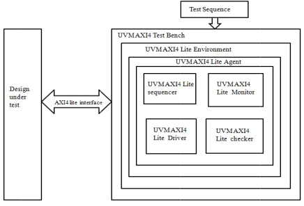
OF UVM B
ON ENVIRO
ite UVM Test benc
nsists of verific ese verificatio fferent interfa
15.
ISSN 2348 e a test bench fo
e of Verilog, V
g classes Libr sability. m verification
e there is a gen g with the f
the checkers. bug, and all th the maximum verification en le, scalable, an ent has a clear
ulation oriente hich is based on acceleration.
of Verificatio
Universal V s layered base nts which can to the sou done to each ey can be reu est (DUT).
ded by the
gy (UVM) su cation.
hich support he effort and th
BASED AXI
ONMENT
ches and Environm
cation compon on component ace protocol o
– 7968 for all those VHDL, and rary which which is neration of features of This helps he compute extent. nvironment nd modular predefined
ed, it also n assertion, on process Verification ed. Where be reused. urce code,
h of these used across Universal upports the TLM are he time
I4 LITE
ments nents which ts can be or for anysystem and can be instantiated. All these have a consistent architecture. And can be used for simulating, driving, monitoring, collecting.
The UVM environment contains virtual sequencer or multi-channel sequence this helps to provide the control of the test environment and synchronizes the timing and data between the different interfaces.
In this project all the UVM components are configured for AXI4 lite protocol.
2.1 AXI4 Lite UVM Verification Components
Depending on the requirement UVM environment consists of various verification components.
2.1.1 AXI4 Lite UVM Data item (Transaction):
In an UVM environment the input to the device under test is called the data item. They might be transactions over the bus, data packets over the bus or instructions to the design under test (DUT).Data item have got fields and attributes depending on the specification. These data are generated according to the requirement and are send to the design under test (DUT). By using System Verilog constraints, constrained based random data can also be generated. This helps to achieve the coverage which is maximum. In this project “rand logic” data type is used to generate the data item randomly. i.e
… rand logic S_AXI_AWREADY, rand logic S_AXI_WREADY, rand logic [0:0] S_AXI_BID, rand logic [1:0] S_AXI_BRESP, rand logic [0:0] S_AXI_BUSER, rand logic S_AXI_BVALID, rand logic S_AXI_ARREADY, rand logic [0:0] S_AXI_RID, rand logic [31:0] S_AXI_RDATA, rand logic [1:0] S_AXI_RRESP, rand logic S_AXI_RLAST, rand logic [0:0] S_AXI_RUSER, rand logic S_AXI_RVALID …
2.1.2 AXI4 Lite UVM Driver:
It is used to drive design under test (DUT).Depending on the requirement it repeatedly receives the data item on request from the sequencer and then samples before driving it to design under test (DUT).If the operation that needs to be performed is read and write, the signals like address, data, read or write, enable and others are
controlled by the driver for all the clock cycles in which these operations are performed.
// get_and_drive will get the random data from the Sequencer
task axi4_lite_driver::get_and_drive(); begin
//item is a transaction reference for the sequencer send_to_dut(item); //send the item to DUT end
end task : get_and_drive
// item. kind indicates different operations done by the driver
case(item.kind)
// AXI_Lite one sequence write operation(support single burst)
WR_DATA: this.AXI_LiteM_1Seq_Write (input [31:0] awaddr, input [31:0] wdata, input [7:0] wait_clk_bready, input[7:0] wmax_wait);
// AXI_Lite one sequence read operation (support single burst)
AXI_LiteM_1Seq_Read (input [31:0] araddr, input [7:0] rmax_wait );
// AXI_Lite Write address channel operation WAC:this.AXI_LiteM_WAC(input [31:0]awaddr); // AXI_Lite Write data channel operation
WDC:this.AXI_LiteM_WDC( input [31:0]wdata, input [7:0] wmax_wait );
// AXI_Lite write response channel operation
WRC:this.AXI_LiteM_WRC(input[7:0] wait_clk_ready); //Read address channel operation
AXI_LiteM_RAC( input [31:0] araddr) //read data channel operation
WRDC:this.AXI_LiteM_RDC( input [7:0rmax_wait); endcase
WRC:this.AXI_LiteM_WRC(input[7:0]wait_clk_ready);
2.1.3 AXI4 Lite UVM Sequencer
It is used send and controls the data items to the UVM Driver. Even though it looks like a simple stimulus generator but it has got advanced features. That is random data item generated can be made constrained based, so as to capture all the unknown bugs in the design under test. These values generated can be made to have the distribution such that the coverage is maximum.
F 2 U e f h
Fig 2:AXi4_lite Se
2.1.4 AXI4 Lite
UVM monitor entity. Checker from the DUT. here and any ch
A mon
conver tester enviro
All the the ch even p
If the D protoc checke checki
//Colle
task axi4_l //Here all t and the inf endtask :co function vo if((m_xactn ARADDR m_xactn.S //Here the w and //write data endfunctio
IJISET ‐ Intern
equencer and Drive
e UVM monito
is not an acti r samples all th . All the cover hecking if requ nitor collects a rts it into a form
and other onment.
e coverage inf hecker. It provi print the trace i Design under T col specificatio
ers available c ing.
ect and Check
lite_monitor::c the data from th formation is pu ollect_data oid axi4_lite_c
n.S_AXI_AW )&&(m_xactn _S_AXI_RDA write address i
a is same as the on :check_it
national Journal of
er Connection [10]
or and checker
ive entity but he signals whic rage informatio uired is also don all the signal in
m, so that it is a components i
formation is al ides an option information. Test (DUT) is on, then the dat can be used t
operation
collect_data(); he dutoutput a ut into analysis
checker::check_ ADDR==m_x .S_AXI_WDA ATA))
is same as the r
e read data is c
f Innovative Scienc www
]
it is a passive ch are received on is collected ne.
nformation and available to the in the UVM
so collected in where we can
based on some ta and protocol to perform the
are collected report. _it(); xactn.S_AXI_ ATA== read address checked ce, Engineering & T w.ijiset.com e d d d e M n n e l e 2.1.5 With of a more UVM provi entiti nothi an ag Depe agent used (mas calle passi trans calle the a In th agent creat envir moni s); m_ch r",thi drive seque er",th 2.1.6 Depe comp UVM supp behav An e passi The UVM Technology, Vol. 2
5 AXI4 Lite UV
h an aim to red verification en e abstract conta M environmen ide the reusabi ies an environ ing but an agen gent
ending on the r t in a verifica to start the t ter) and those d receive agen ive or active saction accordi
d the active ag activities of DU
is project agen t).Hence it con ted by facto ronment. itor=axi4_lite_ hecker=axi4_li is);//checker er=axi4_lite_dr encer=axi4_lit his);//sequence
6 AXI4 Lite UV
ending on the ponents like bu M environme
orted by the vior, topology environment le ive agent can b
uvm_env is th M class library.
Generate t
Performs (checking)
Coverage
And moni
2 Issue 5, May 201
VM Agent
duce the knowl ngineer while ainer called an nt. Sequencers ility. In order t nment integrat nt. All these en
requirement the ation compone
transaction are which respond nts (slave).Age e. Those age ing to the requ ent and those w UT are called p
nt is of type UV ntains all the c
ory method _monitor::type_ ite_checker::ty river::type_id:: e_sequencer::t er VM environme requirement us monitor are ent. The co
environment y and reusabili evel monitor ca be converted in
he environmen It helps to
the constrained the protoc ).
information is tors all the DU
15.
ISSN 2348
ledge, effort an writing the tes agent is suppo , drivers, and to hook up eac tor is required ntities are encap
ere can be mor nt. Those age e called transm d to these tran ents can be con
ents that gen uirement to the which do only m
assive agent.
VM_ACTIVE omponents. Al supported b
_id::create("mo
ype_id::create("
:create("driver" type_id::create
ent
one or many e encapsulated
onfiguration helps to cust ty can also be an also be con nto active and v
nt class provid
d based random ol activity
collected. UT activity.
– 7968
nd the time st bench, a orted by the d monitors
ch of these d which is
psulated in
re than one nt that are mit agents saction are nfigured as nerate the e DUT are monitoring
(i.e. active ll these are by UVM onitor",thi "m_checke ",this); ("sequenc agents or d inside the properties tomize the e achieved. nfigured. A vice versa.
ded by the
m data item. validation
// a f p s a s e
3
L
A S tr d th O to g/build the obje active.
functionvoid ax phase); super.build_pha agent0=axi4_lit set_config_int( endfunction :bu
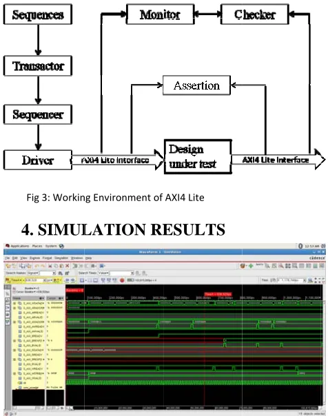
3. WORKIN
LITE
As shown in F Sequences wiransactor whic driver from the he driver the d Output and inpu
o the monitor generate the ch
Fig 3: Workin
4. SIMUL
ect of agent typ
xi4_lite_env::b
ase(phase); te_agent::type_ ("*","is_active" uild_phase
NG ENVIRO
Fig 3 Sequenc ill generate t ch are given t e sequencer TL data is transfer
ut data from th r and the che hecker log.
ng Environment of
LATION RE
Fig 4:AXI4L
pe and configur
build_phase(uv
_id::create("ag ",UVM_ACTIV
ONMENT O
ces are genera the transactio to sequencer. T
LM technique rred to the des he design under ecker. And the
AXI4 Lite
ESULTS
Lite write operation
red it to be
vm_phase
gent0",this); VE);
OF AXI4
ated randomly ons from the
To pass to the is used. From sign under test
r test are given e checker will
n
. e e m . n l
5. C
Tran mode the f the e mode there Tran and U
Henc AMB proto level using defin the d the d
6. F
The verif featu
1 2 3
4
R
[1].Tr Bus I Solut Facul
CONCLUSIO
saction-level m el the system a functional veri effort and the t eling speed the e are open sou
saction-level m UVM.
ce in this proje BA AXI4 bus ocol .And then l modeling met g this method m ned in the prot developed mod development of
UTURE W
project can b fication of AX ures.
1. Burst of da 2. Data width 3. Various ty the protoc 4. Different t implement FIX INC WR
REFERENCE
ransaction-based Interconnects us ions and Kumar lty of Engineerin
Fig 5:AXI4 Lite re
ON
modeling is an at the architectu ification. Usin
time as it incr en RTL techni urce packages modeling (TLM
ect we have im interconnect th n it is verified b thod. The simu
matches with t tocol specificat del can be used
f prototype
ORK
be extended fo XI4 protocol.
ata can be up t h can be varied ypes of handsh
ol. All these ca type of burst ar ted like XED
CR RAP
S
d SoC Design Te sing VHDL (By
rMunusamy ,Mu ng).
ead operation
advanced meth ural level and g this modelin eases the simu
ique [4] [5] [6
available whi M) method like
mplemented the hat is AMBA by using the T ulation results o the handshakin tion document d as a TLM com
or the develop This has the
to 256 beats. d from up to 10
haking are sup an be implemen re supported wh
echniques for AM Daniel C.K. Kh ultimedia Univer
hod used to to perform ng reduces ulation and
6] [8]. And
ch support e OSVVM
e subset of AXI4 Lite Transaction obtained by ng which is t. And also mponent in
pment and following
024 bits. pported by nted hich can be
IJISET ‐ International Journal of Innovative Science, Engineering & Technology, Vol. 2 Issue 5, May 2015.
www.ijiset.com
ISSN 2348 – 7968
[2]. AXI4_specification.pdf
https://capocaccio.ethz.ch/capo/raw-attachement/.../
AXI4_specification.pdf
[3]. Comparing AMBA AHB to AXI Bus using System Modeling. (By Deepak Shankar)
[4].TRANSACTION LEVEL MODELING, An Abstraction Beyond RTL. (By Laurent Maillet-Contoz and Frank Ghenassia, STMicroelectronics, France )
[5]. M. Caldari, M. Conti, M. Coppola, S. Curaba, L. Pieralisi, and C.Turchetti. ”Transaction-level models for AMBA bus architecture usingSystemC 2.0.” Proc. IEEE Conf. Design, Automation and Test in Europe.vol. 2, Mar. 2003.
[6]. From VHDL Register Transfer Level to System C
Transaction LevelModeling: a Comparative Case Study (By Ney Calazans, Edson Moreno, FabianoHessel, Vitor Rosa,
FernandoMoraes, Everton CararaPontifíciaUniversidadeCatólica do Rio Grande do Sul [FACIN-PUCRS] Av. Ipiranga, 6681 - Prédio 30 / BLOCO 4 90619-900 - Porto Alegre – RS – BRASIL)
[7]. J. Lewis. The OS-VVM packages.[Online http://osvvm.org/].
[8].Analysis and Optimization of Transaction Level Models for Multi-Processor System-on-Chip Design (By Hans
GunarSchirner,UNIVERSITY OF CALIFORNIA).
[9]http://en.wikipedia.org/wiki/Advanced_Microcontroller_Bus _Architecture
[10]http://accellera.org/images/downloads/standards/uvm/uvm_ users_guide_1.1.pdf.
[11]
http://en.wikipedia.org/wiki/Universal_Verification_Methodolog y
[12] http://www.doulos.com/knowhow/sysverilog/uvm/
[13]http://accellera.org/images/downloads/standards/uvm/UVM _1.1_Class_Reference_Final_06062011.pdf
[14]http://www.testbench.in.
[15].Transaction Level Modeling in SystemC (Adam Rose, Stuart Swan, John Pierce, Jean-Michel Fernandez Cadence Design Systems, Inc)
[16].http://www.cadence.com/products/fv/enterprise_simulator/ pages/default.aspx
[17].Modeling method to develop an amba axi4lite bus interconnect : A survey . (By Harini H G In IJERT, Volume. 4, Issue. 04 , April – 2015)
[18]www.infocenter.arm.com.
First Author Completed B.E in Electronic and Communication in 2005
![Fig 2F:AXi4_lite Seequencer and Driveer Connection [10]]](https://thumb-us.123doks.com/thumbv2/123dok_us/7834849.1298344/4.612.88.226.63.276/fig-f-axi-lite-seequencer-and-driveer-connection.webp)