Embedded System Development for Multiple
Fault Diagnosis of Induction Motor
S.M. Shashidhara
1, Dr.P. Sangameswara Raju
2Professor, Dept of E&CE, Proudhadevaraya Institute of Technology, Hospet, India 1
Professor, Dept of EEE, SVU College of Engineering, Tirupati, India2
ABSTRACT: With the proliferation of advanced technologies in signal processing, spectrum estimation of AC machines has lead to the accurate and precise identification of different faults. The popular machine in most of the industrial applications is a squirrel cage induction motor and failures of such significant motors may have severe consequences such as product quality, ageing, safety, and costs.
Most of the condition monitoring techniques in induction motors generally involve with single and specific fault identification. This paper proposes a technique for optimized identification of two or more faults of an induction motor. The contribution of this paper is a methodology that suits for hardware development, which integrates induction motor data with cRIO system to identify the faults such as broken rotor bars, eccentricities, stator turns fault and bearing faults. To ensure the performance response of proposed methodology, tests are conducted on a 2 kW induction motor in a laboratory, which show highly satisfactory results that prove its suitability for on-line detection of single and multiple faults in a flexible way through its hardware implementation in a field programmable gate array (FPGA) environment.
KEYWORDS: Induction Motor, Multiple Faults, Fault Diagnosis, Detection, FPGA.
I. INTRODUCTION
Eleactromechanical energy conversion systems (motors and generators) are effectively employed for various industrial applications including renewable energy conversions, electric drive systems, mining, aircraft, and petroleum products, etc. The induction motors dominate other electro-mechanical rotating machines with respect to rotor inertia, maximum efficiency, highest speed capability, size, volume and cost [1]. Hence, the assessment of running conditions and reliability of induction machines are critical to avoid random and catastrophic failures in most of the applications. Consequently, the issue of continuous monitoring and non-invasive diagnosis of these induction machines is of high concern, and is becoming increasingly significant [2].
In the last two decades, a large amount of research work has been reported on using the stator current spectrum to sense the rotor faults associated with mechanical unbalance and rotor broken bars [3-8]. These techniques require highly skilled operator/user in order to distinguish a normal operating condition from a potential failure state. This is so, as the monitored spectral components (either current or vibration) are based on number of factors, including normal operating conditions [9].
Now a day, the employment of cRIOTM offers an attractive technique, w h i c h exhibits flexible and improved performance along with its compact size [18]. This technique has been employed for various applications such as medical equipment monitoring, automatic control in magnetic system and engine control in motor cycle vehicles. Hence, the effort has been made in the effective utilization of Laboratory Virtual Instrument Engineering Workbench (LabVIEW) cRIO with Field Programmable Gate Array (FPGA) environment for the continuous monitoring of induction motor. The flexibility of proposed technique is that, it accepts multiple sensor signals and capable of accommodating custom signal analysis tools. Moreover, this system provides a real-time and continuous monitoring platform. In addition, this proposed system has a special feature of visual inspection opportunity for staff about the condition of the machine.
II. FAULT FREQUENCIES IN INDUCTION MOTORS
It is well known that, a current spectrum of a faulty system is composed of potential fault information. However, the frequency components of each fault can be determined through various techniques. It is also important to know that, just as in vibration analysis, as the fault progresses, its characteristic spectral components continue to increase over a time.
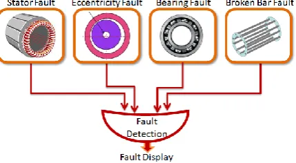
Fig. 1 Detection of multiple faults
A. Bearing faults:
The bearing fault current harmonics can be described [1], [2], and [18], by following equations,
fbng = fs+Nb. fi,o (1)
Where fs is supply frequency of the system. fo and fi are related to outer and inner race, respectively, and Nb is the number of balls, and f0 and fi are given by,
f0= fr
2 1 − BD
PDcos β and fi= fr
2 1 − BD
PDcos β (2)
Where, „BD‟ and „PD‟ are, respectively, the ball diameter and the pitch diameter, and β is the contact angle between the balls and the ball bearing rings.
B. Rotor faults:
End rings and broken bars of the rotor induce the same harmonics in the stator currents. Hence, the amplitude of stator current will be modulated by the slip frequency factor, which is given by 2.s.fs. Here “s” is per unit slip. This increase in the modulation is based on the severity of the fault. In the current spectrum, the harmonics [18-21] due to the rotor fault can be found from the following characteristic equation:
fbrb = fs. 1+ 2. n. s (3)
C. Stator Faults:
The stator current related faults can be identified by using the fault frequency measurement, which can be observed by the FFT analysis of the voltage, current and axial flux signals [18-23].
fsf = fs n 1−s
p + k (4)
Where, „p‟ is the number of pole pairs of the induction motor and „k‟ is an integer. It has been reported that, 2.fs or a combination of rotor frequency (fr), 2.fr, and 2.fs can be an indication of stator faults in vibration based monitoring.
D. Eccentricity Faults:
In the literature, other possible mechanical imbalance faults of induction motor have been reported in [1], [18], [19], and [20]. Eccentricity is also one of the major kinds of induction motor faults in which the frequency analysis is made based on following expression:
fec = fs. 1+ 1−s
p ± n (5)
Where,
fec = eccentricity frequency,
f s= supply frequency,
p = pole pairs, n = 1, 3, 5…
III. REAL-TIME EMBEDDED SYSTEM DEVELOPMENT
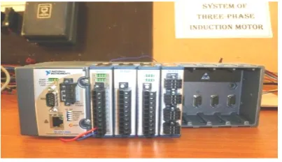
This is the heart of the system which essentially reduces the complexity, running time as well as, it provides tools for monitoring and identification of faults in the system. cRIO technology combines flexibility and the processing power of a field-programmable gate array (FPGA) with greater reliability of a real-time processor. cRIO consists of three constituents (Fig. 2):
Fig. 2 cRIO Module
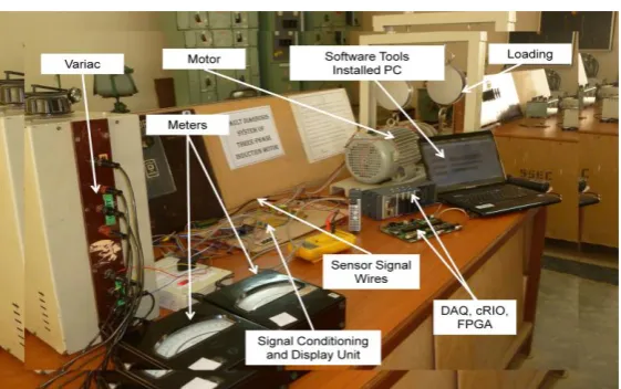
Fig. 3 Experimental Set-Up
Fig. 3 shows the experimental Set-Up of cRIO based Induction Motor fault detection system. In this, the data transfer has been executed effectively through the network port. However, read/write instruction, execution time-critical loop tasks, reading data from machine status has been carried out by FPGA Chassis. The AI module is employed for capturing vibrations, current, voltage and flux signals using suitable signal conditioning devices and sensors. A display module is used to provide an on-line fault diagnosis and display/alarm to the operator/user. It mainly deals with various groups of motor faults and its associated threshold levels. It also indicates the fault status and condition of the machine.
IV. FAULT DETECTION SYSTEM
The cRIO platform features a small, rugged, scalable, modular, embedded architecture comprising of an FPGA, an RT processor and isolated I/O devices. cRIO has industrial class certification for high temperatures, hazardous locations or potentially explosive environments and shock capability. It is a good candidate to be used in an industrial environment.
The cRIO architecture has similarity to that of the desktop systems but with FPGA plug-in boards. The floating-point processor that can be programmed with LabVIEW Real-Time is connected to the FPGA on the backplane through an internal PCI bus. The cRIO modules consist of conversion circuitry (for analog modules), electrical isolation, signal conditioning, permitting direct connection to sensors on the motor [18, 22-24].
Real-time system development is a multistep process that includes (i) programming, (ii) debugging, (iii) compiling, (iv) downloading and (v) deploying. LabVIEW Real-Time is a unique facility, as it creates advanced real-time applications but takes advantage of all the benefits of LabVIEW for Windows graphical programming environment. While developing real-time software, performance must be ascertained at each step of process. The execution speed of each component requires to be measured to ensure that they match their expected performance criteria. During system integration, the performance of the system needs to be continually checked for the same reason.
The uniqueness of this work is the implementation of a highly reliable, low-cost, multichannel, multisensory analysis platform, based on the spectrum estimator, capable of providing an automatic diagnosis of the motor state. This system carries out on-line continuous monitoring with the help of a post-processing module that automatically assesses the estimated spectrum, accordingly to the specific failure under diagnosis. All the approaches mentioned before, require the usage of FPGA technology that allows developing low-cost, rapid and reconfigurable architectures for real-time analyses [18, 24]; Hence, the primary contribution of this work is the utilization of an FPGA based cRIO module for developing an on-line multichannel spectrum analysis based continuous monitoring of multiple sensor signals with an embedded postprocessor for an automatic diagnosis of the machine state.
V. EXECUTION OF SOFTWARE
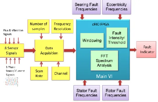
The cRIO based condition monitoring system is programmed using LabVIEWTM along with necessary constraints based on motor condition. This main VI as shown in simplified block diagram Fig. 4 acquires data continuously from the designated channel and carries out the scaling of the data to appropriate engineering units. Then program performs windowing of the signal, and the averaged frequency measurement. Power Spectrum, Power Spectral Density, and FFT are available frequency measurements. The VI returns the frequency resolution and the period of the acquisition time, based on the scan rate and the number of samples.
Fig. 4 Block diagram of the Virtual Instrument Panel with FPGA
The main Virtual Instrument panel comprises of subVIs for the detection of various faults. SubVIs are custom designed for various faults to be detected by the cRIO real-time monitoring software. FPGA performs multiple operations simultaneously, such as, acquiring the data & performing low pass anti-aliasing filtering, and transferring the data via direct memory access. It also drives the status display module.
The Induction machine data analysis is mainly performed in the real-time controller. In this execution, the process sequence is as follows: initialization of data, machine data calibration from relevant sensors, followed by FFT analysis, peak detection of fault frequency and frequency averaging. Once the FFT analysis of induction motor is monitored, a number of subroutines are executed to identify exact faults based on the valid fault frequency equations described in section II. With this, the fault level algorithms are implemented to estimate the specific fault levels based on the peak values of the fault frequencies.
than -45 dB, then the motor would be indicated as faulty, else it comes in marginal band. Threshold values for the peaks of side band frequencies are stored in the program data for comparison and decision-making.
VI. RESULTS AND DISCUSSION
In this work, to ensure the performance and to analyse the steady-state response of the system, various tests were conducted. The steady-state current, voltage, flux and vibration signals are obtained from the motor and are used to detect the multiple faults and their corresponding classification. The time taken for bearing, stator, eccentricities and rotor fault frequency model calculations is 3 ms approximately. Limit testing has taken 28 ms. From the literature, it has been noticed that, the execution time duration of the algorithm for the proposed task is in the standard range for the condition monitoring system of induction motor applications.
The implemented on-line condition monitoring system essentially identifies and detects the single or multiple fault conditions dealt in this paper. Using the cRIO embedded system; Induction Motor fault detection system has been prototyped. Fig. 5 presents the threshold limit testing process on front panel of VI. Fault intensity threshold levels are provided in the program. Fig 6 and 7 show the spectrum analyses of the stator and rotor faults respectively.
Fig. 5 Threshold Limit testing process on front panel of VI
(a) (b)
Fig. 7 Detection of broken rotor bars of Induction Motor (a) Current waveform (b) Spectrum analysis
VII. CONCLUSIONS
In this paper, a cRIO based condition monitoring system for identification of faulty section of an Induction Motor has been described and presented. The existing various fault frequency analyses of Induction Motors are described. Effort is made on the optimized utilization of cRIO system in FPGA environment for fault identification and detection of Induction Motor.
The paper demonstrates the development of software and hardware units, which are established in the reconfigurable cRIO environment. Broken rotor bar fault, stator shorted turns fault, eccentricity and bearings related faults have been tracked and monitored from the proposed method of detection.
REFERENCES
[1] Hachemi, B. M. EI., and Kliman, G. B., “What stator current processing-based technique to use for induction motor rotor faults diagnosis,” IEEE Trans. on Energy Conversion, Vol. 18, No. 2, pp. 238-244, June 2003.
[2] Benbouzid, M. E. H., “Bibligraphy of Induction motors faults detection and diagnosis,” IEEE Trans. Energy Conversion, Vol. 14, No. 4, pp. 1065-1074, December 1999.
[3] Chow, T. W. S., and Fei, G., “Three phase induction machines asymmetrical faults identification using bi spectrum,” IEEE Trans. Energy Conversion, Vol. 10, pp. 688-693, December 1995.
[4] Kilman, G. B., and Stein, J., “Methods of motor current signature analysis,” Elec. Mach. Power Syst., Vol. 20, pp. 463-474, September 1992. [5] Schoen, R. R. T., Habetler, T. G., Kamran, F., and Bartheld, R. G., “Motor bearing damage detection using stator current monitoring,” IEEE
Trans. Ind. Applicat., Vol. 31, pp. 1274-1279, Nov. 1995.
[6] Kilman, G. B., and Stein, J., “Induction motor fault detection via passive current monitoring,” in Proceedings Intl. Conf. Electrical Machines, Vol. 1, pp. 13-17, Cambridge, 1990.
[7] [Schoen, R. R., Lin, B. K., Habetler, T. G., Schlag, J. H., and Farag, S., “An unsupervised, on-line system for induction motor fault detection using stator current monitoring,” IEEE Trans. Indl. Applicat., Vol. 31, pp. 1280—1286, November 1995.
[8] Filippetti, F., Franceschini, G., Tassoni, C., and Vas, P., “A fuzzy logic approach to on-line induction motor diagnostics based on stator current monitoring,” in Proceedings, IEEE-Intrl. Conf., Power tech., Vol. EMD, Sweden, pp. 156-161.
[9] Benbouzid, M. E. H., Vieira, M., and Theys, C., “Induction motors faults detection and localization using stator current advanced signal processing techniques,” IEEE Trans. Power Electron., Vol. 14, No. 1, pp. 14-22, January 1999.
[10] [Ondel, O., Boutlexu, C. E., and Blanco, E., “Fault detection and diagnosis in a set inveter-induction machine through multidimensional membership function and pattern recognition,” IEEE Trans. Energy Conversion, Vol. 24, No. 2, pp. 431-441, June 2009.
[11] Cusido, J., Romeral, L., Ortega, A., Rosero, J. A., and Garcia-Espinosa, A., “Fault detection in induction machines using power spectral density in wavelet decomposition,” IEEE Trans. Indl. Electron., Vol. 55, No. 2, pp. 633-643, February 2008.
[12] Ordaz-Moreno, A., Romero-Troncoso, R. J., Vite-Frias, J. A., Rivera-Guillen, J. R., and Garcia-Perez, A., Automatic online diagnosis algorithm for broken-bar detection on induction motors based on discrete wavelet transform for FPG implementation,” IEEE Trans. Indl. Electron., Vol. 55, No. 5, pp. 2193-2202, May 2008.
[13] Kia, S. H., Henao, H., and Capolino, G. A., “Diagnosis of broken-bar fault in induction machines using discrete wavelet transform without slip estimation,” IEEE Trans. Indl. Appln., Vol. 45, No. 4, pp. 1395-1404, July 2009.
[14] Mahamad, A. K., Saon, S., and Hiyama, T., “Predicting remaining useful life of rotating machinery based artificial neural network,” Comput. Math. Appl., Vol. 60, No. 4, pp. 1078-1087, August 2010.
[16] Bouzida, A., Touhami, O., Ibtiouen, R., Fadel, M., Rezzoug, A., and Beloucherani, A., “Fault diagnosis in industrial induction machines through discrete wavelet transform,” IEEE Trans. Indl. Electron., Vol. 58, No.9, pp. 4385-4395, September 2011.
[17] Romero-Troncoso, R. J., Saucedo-Gallaga, R., Cabal-Yepez, E., Garcia-Perez, A., Osornio-Rios, R. A., Alvarez-Salas, R., Miranda-Vidales, H., and Huber, N., “FPGA-Based online detection of multiple combined Faults in induction motors through information entropy and fuzzy inference,” IEEE Trans. Indl. Electron., Vol. 58, No. 11, pp. 5263-5269, November 2011.
[18] Bakhri, S., Ertugrul, N., Soong, W. L., and Al Sarawi, S., “Investigation and development of a real-time on- site condition monitoring system for induction motors,” in Proceedings Australasian universities Power Engg., Conf. pp. 1-6, Perth, Australia, 9-12, December 2007.
[19] Ondel, O., Glerc, G., Boutleux, E., and Blanco, E., “Fault detection diagnosis in a set Inverter-indcution machine through multi-dimensional membership function and pattern recognition,” IEEE Trans. Energy Conversion, Vol. 24, No. 2, pp. 431-441, June 2009.
[20] Rangel-Magdaleno, J. J., Romero-Troncoso, R. J., Osornio-Rios, R. A., Cabal-Yepez, E., and Contreras- Medina, L. M., “Novel methodology for online half-broken-bar detection on induction motors,” IEEE Trans. Instrumentation and Measurement, Vol. 58, No. 5, pp. 1690-1698, May 2009.
[21] Thomson, W. T., and Fenger, M., “Current signature analysis to detect induction motor faults,” IEEE Trans. Indl. Appl., Mag., vol. 7, pp. 26-34, 2001.
[22] Velmurugan, S., and C. Rajasekaran. "A reconfigurable on-chip multichannel data acquisition and processing (DAQP) system for multichannel signal processing." In Pattern Recognition, Informatics and Medical Engineering (PRIME), 2013 International Conference on, pp. 109-114. IEEE, 2013.
[23] Zhiwei, Wang, Hou Shuming, and Xu Zhe. "Inertial Measurement Unit's Rapid Auto-test System Design Based on cRIO." Missiles and Space Vehicles 006, 2012.